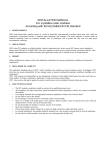
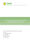
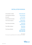
1
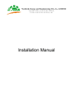
SAFETY & INSTALLATION
MANUAL
PHOTON SOLAR
Crystalline Photovoltaic Modules
- PHOTON SOLAR PH-Series -
Document Status Nov 07, 2013
TABLE OF CONTENTS
PREFACE
2
GENERAL INFORMATION
3
General Safety
3
Installation Safety
3
Fire Safety
4
MECHANICAL INSTALLATION
5
Operation Conditions
5
Site Selection
5
Tilt Angle
5
Mechanical Drawing of Module
6
Mounting
7
ELECTRICAL INSTALLATION
11
Electrical Specifications
11
Module Wiring and Connector
13
Grounding
13
Junction Box with Bypass Diodes
14
MAINTENANCE
15
OWNERSHIP
15
DISCLAIMER OF LIABILITY
15
PHOTON SOLAR Photovoltaik Handel GmbH - Mettmanner Strasse 25 / Haus 14 – D-40699 Erkrath – Germany
Tel: +49-211-280125-0 - Fax: +49-211-280125-29 - Email: [email protected] - Website: www.photon-solar.de
page 1
PREFACE
IMPORTANT! Please read this instruction manual in its entirety before installing, wiring or
using this product in any way. Failure to comply with these instructions will invalidate the
manufactures Limited Warranty for PV Modules. Installers should follow all safety
precautions described in this guide as well as local codes when installing a module.
Thank you for choosing PHOTON SOLAR crystalline solar modules. With proper
operation and maintenance, our modules will provide you with clean, renewable solar
electricity for many years.
This manual provides important safety information regarding the installation,
maintenance and use of the modules that the user and the professional installer should
read carefully and follow. Failure to follow these instructions may result in death, bodily
injury or damage to property.
The installation of solar modules requires specialized skills and should only be performed
by qualified, licensed professionals. Before installing a solar photovoltaic system,
installers should familiarize themselves with its mechanical and electrical requirements.
Keep this guide in a safe place for future reference (care and maintenance) and in case of
sale or disposal of the modules.
The word "module" or "PV module" as used in this manual refers to one or more
PHOTON SOLAR crystalline solar modules.
PHOTON SOLAR Photovoltaik Handel GmbH - Mettmanner Strasse 25 / Haus 14 – D-40699 Erkrath – Germany
Tel: +49-211-280125-0 - Fax: +49-211-280125-29 - Email: [email protected] - Website: www.photon-solar.de
page 2
GENERAL INFORMATION
General safety
• Do not attempts to install, wire, operate or maintain the modules before reading through the manual.
• The installation should only be carried out by qualified licensed personnel.
• When installing the system, abide to all local, regional and national statutory regulations. Contact your local
authorities to determine the required permits before installation.
• One single module may generate more than 30V DC when exposed to direct sunlight. Contact with a DC
voltage of 30V or more is potentially hazardous.
• Do not disconnect under load.
• Modules are designed for outdoor use. Modules can be ground mounted, mounted on rooftops, vehicles or
boats.
• Do not use mirrors or other magnifiers to concentrate sunlight onto the modules.
• Do not apply paint or adhesive to the module top surface.
• Only use equipment, connectors, wiring and support frames suitable for solar electric systems.
Handling safety
• Do not lift the module by grasping the module’s junction box or electrical leads.
• Do not stand or step on the module.
• Do not drop the module or allow objects to fall on the module.
• Do not disassemble the modules or remove any part of the module.
• Do not damage or scratch surfaces or back side of the module.
• Do not drill holes in the frame. This may compromise the frame strength and cause corrosion of the frame.
• Do not scratch the anodized coating of the frame (except for grounding connection). It may cause corrosion
of the frame or compromise the frame strength.
• Work only under dry conditions, and use only dry tools. Do not handle panels when they are wet unless
wearing appropriate protective equipment.
Installation Safety
• Never open electrical connections or unplug connectors while the circuit is under load.
• Do not use a module with broken glass or torn substrate as it may cause electrical shock when contacting
with other module frames and surfaces.
• To avoid the hazard of electrical shock and injury, cover the module’s surface with an opaque material
(cardboard) during installing or working with a module or wiring.
• Use properly insulated tools and appropriate protective equipment to reduce risk of electric shock. Wear
suitable protection to prevent direct contact with 30V DC or greater.
• Do not handle the modules during periods of high wind, thunderstorm, blizzard, heavy snow or any other
severe weather conditions.
• Do not install or electric connect wet modules.
• Do not wear metallic rings, watchbands, ear, nose, lip rings or other metallic objects
PHOTON SOLAR Photovoltaik Handel GmbH - Mettmanner Strasse 25 / Haus 14 – D-40699 Erkrath – Germany
Tel: +49-211-280125-0 - Fax: +49-211-280125-29 - Email: [email protected] - Website: www.photon-solar.de
page 3
• Abide to the safety regulations for all other system components, including wires and cables, connectors,
charging regulators, inverters, storage batteries, rechargeable batteries, etc.
• Only use connectors to connect modules to form a string, or connect to another device. Removing the
connectors will lead to the warranty becoming void.
• Contact with electrically changed parts of the panels, such as terminals, can result in burns, sparks and lethal
shock whether or not the panel is connected.
• Do not touch the PV module unnecessarily during installation. The glass surface and the frame may be hot;
there is a risk of burns and electric shock
• Avoid exposing cables to direct sunlight in order to prevent their degradation.
• Keep children well away from the system while transporting and installing mechanical and electrical
components.
Fire Safety
• Consult your local authority for guidelines and requirements for building or structural fire safety.
• Roof constructions and installations may affect the fire safety of a building; improper installation may create
hazards in the event of a fire.
• The modules have been rated Fire Class C, and are suitable for mounting onto a Class A roof. A
fire-resistant-covering roof rated for such an installation is required for rooftops applications.
• It may be necessary to use components such as earth ground fault circuit breakers, fuses and circuit breakers.
PHOTON SOLAR Photovoltaik Handel GmbH - Mettmanner Strasse 25 / Haus 14 – D-40699 Erkrath – Germany
Tel: +49-211-280125-0 - Fax: +49-211-280125-29 - Email: [email protected] - Website: www.photon-solar.de
page 4
MECHANICAL INSTALLATION
Operation Conditions
PHOTON SOLAR crystalline solar modules are designed for operations under the following conditions:
Ambient Temperature:
-40°C to +40°C
Storage Temperature:
-20°C to +40°C
Operating Temperature:
-40°C to +85°C
Humidity:
≤85RH%
Mechanical Load Pressure:
≤5400Pa (Below 112.78 lb/ft²)
The mechanical load bearing (include wind and snow loads) of the module is based on the mounting methods.
Installer must be responsible for mechanical load calculation according to the system design.
Site Selection
Select a suitable location for installing the modules. In most applications, PHOTON SOLAR crystalline solar
modules should be installed in a location where they will receive maximum sunlight throughout the year. The
modules should be facing south in northern latitudes and north in southern latitudes.
The module will have loss of power output of 10%-15% if the unit is greater than 30 degrees from true
south/north. The module will have loss of power output of 20%-30% if the unit is greater than 60 degrees from
true south/north.
The module should not be shaded at any time. When choosing a site, avoid trees, buildings or obstructions,
which could cast shadows on the modules especially during the winter months when the arc of the sun is lowest
over the horizon. Shading causes loss of output, even though the factory fitted bypass diodes of the modules
will minimize any such loss.
For detailed information on the best installation angle, refer to standard solar photovoltaic installation guides
or consult a reputable solar installer or systems integrator.
• Do not install the modules near naked flame or flammable materials.
• Do not install the modules in a location where it would be immersed in water or continually exposed to water
from a sprinkler or fountain etc.
• Do not install the modules in a marine environment and/or area where salty wind hit directly.
• Do not install the modules in corrosive environment, such as corrosive salt area or sulfurous area, etc.
Tilt Angle
PHOTON SOLAR crystalline solar modules produce the most power when they are facing sunlight directly. The
module tilt angle is measured between the solar module and the ground (See Figure 1). The modules
connected in series should be installed at same orientation and angle. Different orientation or angle may cause
loss of output power due to difference of amount of sunlight exposed to the module. Optimal tilting of
modules is almost the same as the latitude of installation location.
PHOTON SOLAR Photovoltaik Handel GmbH - Mettmanner Strasse 25 / Haus 14 – D-40699 Erkrath – Germany
Tel: +49-211-280125-0 - Fax: +49-211-280125-29 - Email: [email protected] - Website: www.photon-solar.de
page 5
For installations where the modules are attached to a permanent structure, the modules should be tilted for
optimum winter performance. As a rule, if the system power production is adequate in winter, it will be
satisfactory during the rest of the year.
PHOTON SOLAR recommends a minimum installation angle of 10 degrees because this enables dust to be
washed off by rain or dew for greater light intensity. This will also improve ventilation and thus output, because
module performance is better at a lower temperature.
Mechanical Drawing of Module
PHOTON SOLAR Photovoltaik Handel GmbH - Mettmanner Strasse 25 / Haus 14 – D-40699 Erkrath – Germany
Tel: +49-211-280125-0 - Fax: +49-211-280125-29 - Email: [email protected] - Website: www.photon-solar.de
page 6
Module Type
Cell Type
Cell
Dimensions
Installation Hole
Cable Length
Alignment
A*B*C (mm)
E*F/D*F (mm)
G (mm)
Frame
Dimension
H*C*I (mm)
PH-XM-72(5” cell)
Mono-crystalline
6*12
1581*809*35
801*758/1301*758
900
11*35*27
PH-XM-60
Mono-crystalline
6*10
1640*992*40
860*954/1360*954
900
11*40*27
PH-XM-72(6” cell)
Mono-crystalline
6*12
1956*992*50
956*941/1476*941
900
12*50*35
PH-XP-60
Poly-crystalline
6*10
1640*992*40
860*954/1360*954
900
11*40*27
PH-XP-72
Poly-crystalline
6*12
1656*992*50
956*941/1476*941
900
12*50*35
PH-250P-60 EU
Poly-crystalline
6*10
1640*992*40
860*954/1360*954
900
12x40x22
PH-270M-60 EU
Mono-crystalline
6*10
1650*1000*42
-
1000
12x42x22
Mono-crystalline
6*10
1650*1000*42
-
1000
12x42x22
Poly-crystalline
6*10
1650*992*50
800*942/1300*954
900
12x50x35
PH-265M-60 EU
– Black Line
PH-250P-60 (HDS)
– INT
Tabelle 1: Module Mechanical Dimensions
Mounting
PHOTON SOLAR crystalline solar modules can be mounted by using the following methods:
- Modules can be mounted by using mounting holes at the module frame with corrosion-proof screws.
- Modules can be mounted by using suitable module clamps on the long side of the module frame.
- Modules can be mounted by using suitable module clamps on the short side of the module frame.
Pleased be noted that PHOTON SOLAR will not provide related BOS components, the system installer or
trained professional personnel must be responsible for the PV system’s design, installation, and mechanical
load calculation and security of the system.
A)
Module installed with mounting holes
The frame of each module has 8 mounting holes (length* Width: 14mm*9mm) used to secure the modules
to supporting structure. The module frame must be attached to a mounting rail using M8 corrosion-proof
screws together with spring washers and flat washers. Use 4 or 8 symmetrical mounting holes on the
modules for different loads as pointed by the red arrows in Figure 3. Please find detailed mounting
information as shown in Figure 3 as following:
PHOTON SOLAR Photovoltaik Handel GmbH - Mettmanner Strasse 25 / Haus 14 – D-40699 Erkrath – Germany
Tel: +49-211-280125-0 - Fax: +49-211-280125-29 - Email: [email protected] - Website: www.photon-solar.de
page 7
B)
Clamping installation – On the long side of the frame
Use a certain number of clamps to fix PHOTON SOLAR crystalline solar modules on the mounting rail. The
module clamps should not come into contact with the front glass and must not deform the frame. Be sure to
avoid shadowing effects from the module clamps. The module frame is not to be modified under any
circumstances.
When choosing this type of clamp-mounting method, please be sure to use at least four clamps on each
module, two clamps should be attached on each long side of the module. Depending on the local wind and
snow loads, additional clamps may be required to ensure the module can bear the load. The mounting rail
and the clamps center line can be moved along on the long side of the frame but recommended to be within
the red arrow area in Figure 4 (area K). Please find detailed mounting information as shown in Figure 4 as
following:
PHOTON SOLAR Photovoltaik Handel GmbH - Mettmanner Strasse 25 / Haus 14 – D-40699 Erkrath – Germany
Tel: +49-211-280125-0 - Fax: +49-211-280125-29 - Email: [email protected] - Website: www.photon-solar.de
page 8
Module Type
Cell Type
PH-XM-72(5” cell)
Dimensions (mm)
A*B
J
K
Mono-crystalline
1581*809
50
380
PH-XM-60
Mono-crystalline
1640*992
50
400
PH-XM-72(6” cell)
Mono-crystalline
1956*992
50
500
PH-XP-60
Poly-crystalline
1640*992
50
400
PH-XP-72
Poly-crystalline
1956*992
50
500
PH-250P-60 EU
Poly-crystalline
1640*992
50
400
PH-270M-60 EU
Mono-crystalline
1650*1000
50
400
PH-265M-60 EU – Black Line
Mono-crystalline
1650*1000
50
400
PH-250P-60 (HDS) – INT
Poly-crystalline
1640*992
50
400
Tabelle 2: Module Mechanical Dimensions when clamp on the long side of the frame
C)
Clamping installation- On the short side of the frame
Use a certain number of clamps to fix PHOTON SOLAR crystalline solar modules on the mounting rail. The
module clamps should not come into contact with the front glass and must not deform the frame. Be sure to
avoid shadowing effects from the module clamps. The module frame is not to be modified under any
circumstances.
When choosing this type of clamp-mounting method, please be sure to use four or six clamps on each module.
Two clamps should be attached on each short side of the module. Depending on the local wind and snow loads,
one clamp should be attached on each long side of the module if needed. The mounting rail and the clamps
center line can be moved along on the short side of the frame but recommended to be within the red arrow
area in Figure 5 (area M) Please find detailed mounting information as shown in Figure 5 as following:
PHOTON SOLAR Photovoltaik Handel GmbH - Mettmanner Strasse 25 / Haus 14 – D-40699 Erkrath – Germany
Tel: +49-211-280125-0 - Fax: +49-211-280125-29 - Email: [email protected] - Website: www.photon-solar.de
page 9
Module Type
Cell Type
PH-XM-72(5” cell)
Dimensions (mm)
A*B
J
K
Mono-crystalline
1581*809
50
150
PH-XM-60
Mono-crystalline
1640*992
50
200
PH-XM-72(6” cell)
Mono-crystalline
1956*992
50
200
PH-XP-60
Poly-crystalline
1640*992
50
200
PH-XP-72
Poly-crystalline
1956*992
50
200
PH-250P-60 EU
Poly-crystalline
1640*992
50
200
PH-270M-60 EU
Mono-crystalline
1650*1000
50
200
PH-265M-60 EU – Black Line
Mono-crystalline
1650*1000
50
200
PH-250P-60 (HDS) – INT
Poly-crystalline
1640*992
50
200
Tabelle 3: Module Mechanical Dimensions when clamp on the short side of the frame
PHOTON SOLAR Photovoltaik Handel GmbH - Mettmanner Strasse 25 / Haus 14 – D-40699 Erkrath – Germany
Tel: +49-211-280125-0 - Fax: +49-211-280125-29 - Email: [email protected] - Website: www.photon-solar.de
page 10
For any above suggested installation method, sufficient clearance between the module frame and the
mounting surface is required wiring damage and to allow cooling air to circulate around the back of the module.
This also allows any condensation or moisture to dissipate. The recommended stand-off height is 115mm. the
module should never be sealed to the mounting surface with sealant that prevents air from circulating under
the module. Clearance of 7mm or more between modules is required to allow for thermal expansion of the
frames.
ELECTRICAL INSTALLATION
PHOTON SOLAR crystalline solar modules should be installed by qualified professionals only. The process
involves electricity and can be dangerous if the installing personnel are not familiar with the appropriate
safety procedures.
PHOTON SOLAR crystalline solar modules are qualified for application class A: Hazardous voltage (IEC
61730: higher than 50V DC; EN 61730: higher than 120V), hazardous power applications (higher than 240W)
where general contact access is anticipated (Modules qualified for safety through EN IEC 61730-1 and -2
within this application class are considered to meet the requirements for Safety Class II).
Several modules are connected in series and then in parallel to form a PV array, especially for applications
with a high operation voltage. Do not use modules of different configurations in the same system. If
modules are connected in series, the total voltage is equal to the sum of individual voltages. For
applications requiring high currents, several photovoltaic modules can be connected in parallel; the total
current is equal to the sum of individual currents.
The maximum number of modules connected in series = Vmax system / Voc at STC. When designing the PV
system, please always take into consideration the variation of the voltage under different temperatures
(please check the respective temperature coefficients of the modules, the Voc of the modules will be rise
when the temperature drops).
Electrical Specifications
PHOTON SOLAR crystalline solar modules electrical ratings are measured under Standard Test Conditions
(STC, irradiance of 1000W/m2, AM 1.5 spectrum, cell temperature 25°C /77°F). Under normal outdoor
conditions , a module may produce more current or voltage than its STC rated power. Accordingly, during
system design, Short-Circuit Current and Open-Circuit Voltage should be multiplied by a factor of 1.25 to
determine component voltage ratings, conductor ampacity, fuse rating and the size of the controls
connected to the modules or system output.
Tables 4, 5, 6, 7, 8, below are the major electrical characteristics of PHOTON SOLAR crystalline solar modules at
STC appear on each module label. The electrical characteristics are within ±10 percent of the indicated values of
Isc, Voc, Imp, and Vmp.
PHOTON SOLAR Photovoltaik Handel GmbH - Mettmanner Strasse 25 / Haus 14 – D-40699 Erkrath – Germany
Tel: +49-211-280125-0 - Fax: +49-211-280125-29 - Email: [email protected] - Website: www.photon-solar.de
page 11
PHOTON SOLAR Photovoltaik Handel GmbH - Mettmanner Strasse 25 / Haus 14 – D-40699 Erkrath – Germany
Tel: +49-211-280125-0 - Fax: +49-211-280125-29 - Email: [email protected] - Website: www.photon-solar.de
page 12
PH-265M-60 EU
PH-250P-60 (HDS)
– Black Line
– INT
32,40
31,90
30
8,12
8,45
8,40
8,20
Leerlauf Spannung (Voc)
37,80
38,47
37,90
37,20
Kurzschluss Strom (Isc)
8,60
9,25
9,20
8,85
Maximalleistung – Pmax (W)
183
199,14
195,45
Elektrische Eigenschaften
PH-250P-60 EU
PH-270M-60 EU
Maximalleistung Spannung – Vmp (V)
31,17
Maximalleistung Strom – Imp (A)
Maximale Seriensicherung (A)
16
15
1000
1000
Maße (mm)
1650*1000*42
1650*992*50
Gewicht (Kg)
19
21
Maximale Systemspannung (VDC)
Tabelle 9: Specifications for EU Series and HDS - INT
Module Wiring and Connector
PHOTON SOLAR crystalline solar modules has two 4mm² diameter type standard 90°C sunlight resistant
output cables each terminated with plug & play connectors. This cable is suitable for applications where wiring
is exposed to the direct rays of the Sun. For a series electrical connection, connect positive (+) connector of first
module to the negative (-) connector of the second module.
All wiring should be completed in accordance with all applicable state and local electrical codes. During system
design, Short-Circuit Current (Isc) and Open-Circuit Voltage (Voc) should be multiplied by a factor of 1.25 to
determine component voltage, rating, conductor ampacity, fuse rating and the size of the controls connected
to the modules or system output.
PHOTON SOLAR suggests that every series module string should be fused prior to be connected with other
strings. Please refer to the applicable regional and local codes for additional fuse requirements. When
necessary, please install blocking diodes to protect modules or system been damaged by reverse current.
Do not short the positive and the negative of a single module. Do not disconnect under load. Be sure
connectors have no gap between the insulators. A gap can cause fire hazard and/or danger of an electrical
shock.
PHOTON SOLAR Photovoltaik Handel GmbH - Mettmanner Strasse 25 / Haus 14 – D-40699 Erkrath – Germany
Tel: +49-211-280125-0 - Fax: +49-211-280125-29 - Email: [email protected] - Website: www.photon-solar.de
page 13
Grounding
All PHOTON SOLAR crystalline solar module frames and mounting racks must be properly grounded in
accordance with the appropriate national electrical code. Proper grounding is achieved by connecting the
module frame(s) and structural members contiguously one to another using a suitable grounding conductor.
Holes provided for this purpose on the module frame are identified in chart 4. The grounding conductor or
strap may be copper, copper alloy, or other material acceptable for use as an electrical conductor per
respective National Electrical Codes. The grounding conductor must then make a connection to earth using a
suitable earth ground electrode.
Attach a separate conductor as grounding wire to one of the 6mm diameter grounding holes on the module
frame as identified in Figure 6 with a set of M6 screw, cup washer, tooth washer, and M6 nut. Please note that a
star washer is used between the flat washer and the module frame ( as shown in Figure 6). This washer is used
to avoid corrosion due to dissimilar metals. Tighten the screw securely to ensure positive electrical contact with
the frame.
Junction Box with Bypass Diodes
Partial shading of an individual module can cause a reverse voltage across the shaded module. Current is then
forced go through the shaded area by the other modules.
When a bypass diode is wired in parallel with the series string, the forced current will flow through the diode
and bypass the shaded SPV module, thereby minimizing module heating and array current losses.
Each PHOTON SOLAR crystalline solar module has a TÜV approved junction box with 3 to 6 bypass diodes
already installed.
PHOTON SOLAR Photovoltaik Handel GmbH - Mettmanner Strasse 25 / Haus 14 – D-40699 Erkrath – Germany
Tel: +49-211-280125-0 - Fax: +49-211-280125-29 - Email: [email protected] - Website: www.photon-solar.de
page 14
MAINTENANCE
PHOTON SOLAR crystalline solar modules require minimal maintenance. Given a sufficient tilt (at least 15°), it is
not generally necessary to clean the modules (rainfall will have a self cleaning effect). Regular maintenance is
required to keep modules clear of snow, bird droppings, seeds, pollen, leaves, branches, dust and dirt spots.
When there is a noticeable buildup of soiling deposits on the module surface, wash the PV array using water
without cleaning agents and a gentle cleaning implement (a sponge), during the cool of the day. Dirt must
never be scraped or rubbed away when dry, as this will cause micro-scratches. If snow is present, a brush with
soft bristles can be used to clean the surface of the module.
Once a year the modules need to be inspected for tightness of screws securing the modules to the racking
frame. The general condition of the wiring needs to also be inspected. Loose hardware could result in damage
to the panel. Strong wind conditions could loosen the mounting devices.
Do not change the PV components (diode, junction box, plug connectors).
If you need electrical or mechanical inspection or maintenance, it is recommended to have a licensed,
authorized professional carry out the inspection or maintenance to avoid hazards of electric shock or injury.
WARNING: For any electrical maintenance, the PV system must first be shut down. Improper maintenance
can cause lethal electric shock and/or burns.
OWNERSHIP
This manual is the proprietary property of PHOTON SOLAR Photovoltaik Handel GmbH. No part of this
manual may be reproduced or copied without the express written permission of PHOTON SOLAR
Photovoltaik Handel GmbH. Any unauthorized use of this manual or its contents is strictly prohibited. No
license is granted by implication or under any patent or patent rights. Any and all intellectual property rights
in or related to the PV modules are and shall remain the property of PHOTON SOLAR Photovoltaik Handel
GmbH. All rights are expressly reserved.
DISCLAIMER OF LIABILITY
The installation techniques, handling and use of PHOTON SOLAR crystalline solar modules are beyond
company control. Therefore PHOTON SOLAR does not accept responsibility and expressly disclaims liability for
any loss, damage, or expense arising out of or in any way connected with such installation, operation, use or
maintenance.
PHOTON SOLAR bears no responsibilities for any infringement of rights of third parties that may result from the
use of the module. No license is granted by implication or under any patent or patent rights.
The information in this manual is based on PHOTON SOLAR’s best knowledge and experience and is believed
to be reliable; but such information including product specification (without limitations) and suggestions do
not constitute a warranty, express or implied. PHOTON SOLAR reserves the right to change the manual, the PV
produce, the specifications, or product information sheets without prior notice.
PHOTON SOLAR Photovoltaik Handel GmbH - Mettmanner Strasse 25 / Haus 14 – D-40699 Erkrath – Germany
Tel: +49-211-280125-0 - Fax: +49-211-280125-29 - Email: [email protected] - Website: www.photon-solar.de
page 15