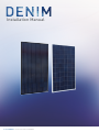
1
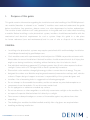
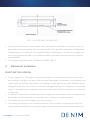
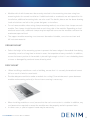
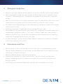
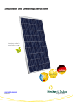
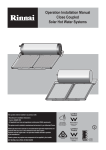
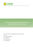
Installation Manual
© 2015 DENIM. Installation Manual DENIM
© 2015 DENIM. Installation Manual DENIM
I
Installation Manual
DENIM
Thank you for choosing DENIM photovoltaic (PV) module. This guide contains important information regarding the installation, limitation and maintenance etc. of the product. Please read this
manual carefully and understand thoroughly before attempting the installation and operation of PV
modules. Keep this guide in a proper place for further reference.
CONTENT:
1.
PURPOSE OF THIS GUIDE3
GENERAL
SAFETY PRECAUTION FOR INSTALLING A SOLAR PHOTOVOLTAIC SYSTEM
2.
PRODUCT IDENTIFICATION5
3.
INSTALLATION AND OPERATION6
SELECTION THE LOCATION
SELECTING THE PROPER SUPPORT FRAME
GROUND MOUNT
ROOF MOUNT
POLE MOUNT
GENERAL INSTALLATION
GROUNDING
4.
WIRING AND CONNECTION12
5.
MAINTENANCE AND CARE12
6.
TECHNIQUE PARAMETERS13
7.
DIMENSION DRAWING14
8. RACK LESS PV MODULE INSTALLATION GUIDE
17
Please note:
The
contents
and
specifications
hereof
may
vary
with
the
product
design.
Solarclarity BV reserves the right to make change to the installation guide without
prior notice.
© 2015 DENIM. Installation Manual DENIM
2
I.
Purpose of this guide
This guide contains information regarding the installation and safe handling of the DENIM photovoltaic module (hereafter is referred to as “module”). Installers must read and understand the guide
before installation. Any questions, please contact our sales department for further explanations.
The installer should conform to all safety precautions in the guide and local codes when installing
a module. Before installing a solar photovoltaic system, installers should become familiar with the
mechanical and electrical requirement for such a system. Keep this guide in a safe place
for future reference (care and maintenance) and in case of sale or disposal of the modules.
GENERAL
• Installing solar photovoltaic systems may require specialized skills and knowledge. Installation
should be performed only by qualified persons.
• Each module comes with a permanently attached junction. DENIM can provide customers with
fitted cables for ease of installation if desired. Installers should assume the risk of all injury that
might occur during installation, including, without limitation, the risk of electric shock.
• One individual module may generate DC voltages greater than 30 volts when exposed to direct
sunlight. Contact with a DC voltage of 30V or more is potentially hazardous.
• Photovoltaic solar modules change light energy to direct-current electrical energy. They are
• designed for outdoor use. Modules may be ground mounted, mounted on rooftops, wall, vehicles
or boats. Proper design of support structures is responsibility of the system designers and
• installers. Use of mounting holes is suggested in a following paragraph.
• Do not attempt to disassemble the modules, and do not remove any attached nameplates or
• components from the modules. Do not disconnect under load.
• Do not apply paint or adhesive to module top surface.
• Do not use mirrors or other magnifiers to artificially concentrate sunlight on the modules. Do
• not expose Composite film backsheet foils directly to sunlight.
• Take care not to bump the edges or corners of the module against any obstructions after
• unpacking.
• The double glass module should be handled carefully. Non-slip gloves are required when
• handling and during installation.
© 2015 DENIM. Installation Manual DENIM
3
• When installing the system, abide with all local, regional and national statutory regulations. Obtain a building permit where necessary.
• Clearance distance is 10cm.
SAFETY PRECAUTION FOR INSTALLING A SOLAR PHOTOVOLTAIC SYSTEM
• Solar modules produce electrical energy when light shines on their front surface. The DC voltage may exceed 30V. If modules are connected in series, the total voltage is equal to the sum of
the individual module voltages. If modules are connected in parallel, the total current is equal to
the sum of individual module currents.
• When series connection, the maximum total number of series modules shouldn’t exceed N.
N is the number of series modules. N= Maximum system voltage / Voc, at standard condition,
AM1.5,temperature 25°C.
• Also when parallel connection, the maximum total number of parallel modules shouldn’t exceed N. N is the number of parallel modules. N= Maximum fuse current / Isc . at standard condition, AM1.5,temperature 25°C.
• Keep children well away from the system while transporting and installing mechanical and electrical components.
• Completely cover the module with an opaque material during installation to keep electricity from
being generated.
• Do not wear metallic rings, watchbands, ear, nose, lip rings or other metallic devices while
installing or troubleshooting photovoltaic systems.
• Use only insulated tools that are approved for working on electrical installations.
• Abide with the safety regulations for all other components used in the system, including wiring
and cables, connectors, charging regulators, inverters, storage batteries and rechargeable batteries, etc.
• Use only equipment, connectors, wiring and support frames suitable for a solar electric system.
• Always use the same type of module within a particular photovoltaic system.
• he electrical characteristics are within ±10 percent of the indicated values of Isc, Voc, and Pmax
under standard test conditions (irradiance of 100mW/cm2, AM 1.5 spectrums, and a cell temperature of 25°C (77°F))
• Under normal outdoor conditions the module will produce current and voltages that are different from those listed in the date sheet. Data sheet values are values expected at standard test
conditions. Accordingly, during system design, values of short-circuit current and open-circuit
© 2015 DENIM. Installation Manual DENIM
4
voltage should be multiplied by a factor of 1.25 when determining component voltage ratings,
conductor ratings, fuse ratings and size of controls connected to the modules or system output.
• The module are qualified for application class A: Hazardous voltage (IEC61730: higher than 50V
DC; EN61730: higher than120V), hazardous power application (higher than 240W) where general
contact access is anticipated (modules qualified for safety through EN IEC61730-1 and -2 within
this application class are considered to meet the requirements for Safety Class II.
• Fire Resistance rated Class is Class C. Fire test class covers tested materials (especially EVA
and Composite film backsheet) only.
2.
Product Identification
Each module has three labels providing the following information:
• Nameplate: Describes the product type,rated power,rated current,rated voltage,open circuit voltage,short circuit current,all are measured under STC;weight, dimension,the maximum system voltage and the Maximum fuse rating are all shown on the nameplate.
• Barcode: Each module has a unique serial number, see FIG.1 as below, the serial number has
15 digits. The capital letter “D” is the short name for DENIM. The second digit refers to the cell
manufacturer, capital letters used to represent, for example, “A”. And the 3rd digit refers to the
modules manufacturer address, capital letters used to represent, for example, “C”. The 4th
digit refers to the modules production month, capital letters used to represent. For example,
“A” refers to “January”, ”L” refers to “December”. The 5th digit refers to the modules production
workshop, “1” refers to the “1 workshop”. The 6th and 7th digits refer to the modules production
year, for example, “12” refers to the year of “2012”. The 8th to 13th six digits refer to serial number from “000001” to “999999”. The 14th refers to the identification code for the type of cells,
capital letters used to represent, but for the traditional modules it can be omitted. For example,
“A” refers to “New Pattern”. The last digit refers to bonded products, capital letter “ F” used to
represent, but for the non-bonded products it can be omitted. There are three barcodes on one
module. One is permanently attached to the interior of the module visible when viewing from the
front of the module. This barcode is inserted at the laying-up process. One is attached near the
nameplate. And another is attached on the paper run-card.
© 2015 DENIM. Installation Manual DENIM
5
DX X X XX X X X X X XX X F
FIG 1: THE CODE RULE OF BARCODE
• There are three barcodes on one module. One is permanently attached to the interior of the module visible when viewing from the front of the module. This barcode is inserted at the beginning
of laminating. One is attached to the aluminum frame. And another is attached to the paper runcard. Do not remove the label. If you remove the label, the product warranty will be not guaranteed by DENIM.
• The modules would be named: “DENIM SC G | P/M***##-**”. 3.
Mechanical Installation
SELECTING THE LOCATION
• In most applications, PV modules should be installed in a location where they will receive maximum sunlight throughout the year. In the Northern Hemisphere, the modules should typically face
south, and in the Southern Hemisphere, the modules should typically face north. Modules facing
30 degrees away from true South (or north) will lose approximately 10 to 15 percent of their power
output. If the module faces 60 degrees away from true South (or North), the power loss will be 20
to 30 percent.
• For detailed information on the best elevation tilt angle for the installation, refer to standard solar
photovoltaic installation guides or a reputable solar installer or systems integrator.
• The module should not be shaded at any time of the day.
• According to the design of our installation manual, Final customers could adopt not only thescrew-installation method but also the press-type connection method to make the frame supporting.
© 2015 DENIM. Installation Manual DENIM
6
• Put the modules on the frame and put on the screws and then combine them firmly after put
on all the gaskets. The module frame is made of anodized aluminum, and therefore corrosion
can occur if the module is subject to a salt-water environment with contact to a rack of another
type of metal. (Electrolysis Corrosion) if required. PVC or stainless steel washers can be placed
between the solar module frame and support structure to prevent this corrosion.
• Module support structures that are to be used to support modules should be wind rated and
approved for use by the appropriate local and civil codes prior to installation. Do not use module
near equipment or in locations where flammable gases can be generated or collected.
SELECTING THE PROPER SUPPORT FRAME
• Always observe the instructions and safety precautions included with the support frames to be
used with the modules.
• Do not attempt to drill holes in the glass surface or additional mounting holes in the frame. To
do so will void the warranty.
FIG 2: SELECT THE PROPER SUPPORT FRAME
© 2015 DENIM. Installation Manual DENIM
7
• Modules which with frame must be securely attached to the mounting structure using four
mounting holes for normal installation. If additional wind or snowloads are anticipated for this
installation, additional mounting holes are also used. The details please see the above drawing.
Load calculations are left to the system designers or installers.
• For no frame modules when using clamp-mounting method, use at least four clamps on each
module. Two clamps should be attached on each long side of the module. Depending on local
wind and snow loads, additional clamps may be required to ensure that modules can bear the
maximum expected load.
• The support module mounting structure must be made of durable, corrosion-resistant and
UV-resistant material.
GROUND MOUNT
• Select the height of the mounting system to prevent the lowest edge of the module from being
covered by snow for a long time in winter in areas that experience heavy snowfalls. In addition,
assure the lowest portion of the module is placed high enough so that it is not shaded by plants
or trees or damaged by sand and stone driven by wind.
ROOF MOUNT
• When installing a module on a roof or building, ensure that it is securely fastened and cannot
fall as a result of wind or snow loads.
• Provide adequate ventilation under a module for cooling (10cm minimum air space between
module and mounting surface), a fire resistant covering is necessary.
• When installing module on a roof, ensure that the roof construction is suitable. In addition, any
roof penetration required to mount the module must be properly sealed to prevent leaks.
• In some cases, a special support frame may be necessary.
© 2015 DENIM. Installation Manual DENIM
8
• The roof installation of solar modules may affect the fireproofing of the house construction.
• The modules are rated fire Class C, and are suitable for mounting over a class A roof. Do not
install modules on a roof or building during strong winds in case of accidents.
POLE MOUNT
• When installing a module on a pole, choose a pole and module mounting structure that will
withstand anticipated winds for the area.
GENERAL INSTALLATION
• Frame module mounting must use the pre-drilled mounting holes in the frame.
• The most common mounting is achieved by mounting the module using the four symmetry
holes close to the inner side on module frames.
• If excessive wind or snow loads are expected, all eight mounting holes must be used.
• The Mechanical load 2400Pa and 5400Pa have been passed for module type DENIM SC G | P295
WW - 72 with 8 mounting holes used.
FIG 3: MECHANICAL LOAD
© 2015 DENIM. Installation Manual DENIM
9
• Do not lift the module by grasping the module’s junction box or electrical leads. Do not stand or
step on module. Do not drop module or allow objects to fall on module. Do not set the module
down on any hard surface.
• For no frame modules when using clamp-mounting method, use at least four clamps on each
module. Two clamps should be attached on each long side of the module. Depending on local
wind and snow loads, additional clamps may be required to ensure that modules can bear the
maximum expected load.
Clamps arrangement
(This A is 1652mm, B is 330mm. if three clamps for each side, additional clamp in the middle of the panel)
• To avoid glass breakage, do not place any heavy objects on the module. Inappropriate transport
and installation may break module.
GROUNDING INSTALLATION
Grounding PV modules is necessary to reduce or eliminate shock and fire hazards. The installer of a
PV system is responsible for grounding each module frame. It is recommended to ground each module frame at the provided grounding holes (6 mm diameter, marked with the grounding symbol).
The grounding holes could be found in the figure below. The ground connections between modules
must be approved by a qualified electrician. The main earth ground must only be connected by a
qualified electrician.
© 2015 DENIM. Installation Manual DENIM
10
FIG 4: GROUNDING HOLES
All module frames and mounting racks must be properly grounded. The grounding wire must be
properly fastened to the module frame to assure good electrical contact. Use the recommended
type, or an equivalent, connector for this wire.
If the support structure is made of metal, the surface of the structure must be electroplated and
have excellent conductivity.
Proper grounding is achieved by connecting the module frame(s) and structural members contiguously using a suitable grounding conductor.
The grounding conductor must then make a connection to earth ground electrode. We recommend
the lay-in lug when grounding. The rack must also be grounded unless it is mechanically connected
by nuts and bolts to the grounded PV modules.
Attach a separate conductor as grounding wire to one of the 6mm diameter grounding holes marked ‘GR’ on the module frame with a set of M4 or M5 screw, cup washer, flat washer, tooth washer,
and M4 or M5 nut. This is to ensure positive electrical contact with the frame.
FIG 5: SCHEMATIC DRAWING FOR DENIM PV MODULE GROUNDING
© 2015 DENIM. Installation Manual DENIM
11
4.
Wiring and connection
• Before this procedure, please read the operation instructions of the PV control system carefully.
• Make wiring by Multi-connecting cables between the PV modules in series or parallel connection, which is determined by user’s configuration requirement for system power, current and
voltage.
• Open the connection box of the control system and connect the cabled from the PV arrays to the
connection box in accordance with the installation indication of the PV control systems.
• All module frames and mounting racks must be properly grounded in accordance with local and
national electrical codes.
• Follow the requirements of applicable local and national electrical codes.
• Each module has two 4mm2 diameter type standard 90°C sunlight resistant output cables each
terminated with plug&play connectors. This cable is suitable for applications where wiring is exposed to the direct rays of the sun. We recommend that all wiring and electrical connections
comply with the appropriate national electrical code.
• For field connections, use the minimum 4mm2 diameter copper wire insulated for a minimum
of 90°C and sunlight resistant as well.
5.
Maintenance and Care
• A built up of dust or dirt on the module(s) front face will result in a decreased energy output.
Clean the panel(s) preferably once per annum if possible (dependant on site conditions) using a
soft cloth dry or damp, as necessary.
• Never use abrasive material under any circumstances.
• Examine the PV module(s) for signs of deterioration. Check all wiring for possible rodent
damage, weathering and that all connections are tight and corrosion free. Check electrical leakage to ground.
• Check fixing screws and mounting brackets and tight, adjust and tighten as necessary.
© 2015 DENIM. Installation Manual DENIM
12
6.
Technique Parameters
DENIM SC G | M ***##-72, “***”stands for power from 170W to 215W in increment of 5 W.
ELECTRICAL SPECIFICATIONS
SC E | P240
SC E | P250
SC E | P260
DENIM SC G | M ***##-72, “***”stands for power from 255W to 320W in increment of 5 W.
DENIM SC G | M ***##-60, “***”stands for power from 210W to 295W in increment of 5 W.
DENIM SC G | M ***##-54, “***”stands for power from 190W to 265W in increment of 5 W.
DENIM SC G | M ***##-48, “***”stands for power from 175W to 235W in increment of 5 W.
DENIM SC G | M ***##-36, “***”stands for power from 130W to 175W in increment of 5 W.
DENIM SC G | P ***##-72, “***” stands for power from 255W to 305W in increment of 5 W.
DENIM SC G | P ***##-60, “***” stands for power from 210W to 255W in increment of 5 W.
DENIM SC G | P ***##-54, “***” stands for power from 190W to 230W in increment of 5 W.
DENIM SC G | P ***##-48, “***” stands for power from 175W to 205W in increment of 5 W.
DENIM SC G | P ***##-36, “***” stands for power from 130W to 150W in increment of 5 W.
TEMPERATUUR COËF.
DENIM SC G | P ***##-72, “***” stands for power from 275W to 335W in increment of 5 W.*
DENIM SC G | P ***##-60, “***” stands for power from 230W to 275W in increment of 5 W.*
DENIM SC G | P ***##-54, “***” stands for power from 210W to 250W in increment of 5 W.*
DENIM SC G | P ***##-48, “***” stands for power from 185W to 220W in increment of 5 W.*
DENIM SC G | P ***##-36, “***” stands for power from 140W to 165W in increment of 5 W.*
The ‘DENIM’ series. include BB and WW modules.
Note:
• The electrical data relates to standard test conditions [STC]: 1,000 W/m2; AM 1,5; 25°C.
• Performance deviation of Pmpp: -/+ 3%.
• Performance deviation of Voc[V],Isc[A],Vmpp [V] and Impp [A]: -/+ 10%.
• Maximum surface load capacity : 5,400 Pa
• Temperature range: – 40 °C to + 85 °C
• Certified in accordance with IEC 61215, IEC 61730-1/2 and UL 1703.
• The recommended maximum series is calculated at standard condition, AM1.5,temperature
25°C.
© 2015 DENIM. Installation Manual DENIM
13
7.
Dimension drawings
1) DENIM SC G | M295-72 Series and DENIM SC G| P285-72 Series dimension drawing
FIG 6: DENIM SC| G M295-72 SERIES AND DENIM285-72P SERIES DIMENSION DRAWING
2) DENIM SC G | M195-72 Series dimension drawing
FIG 7: DENIM SC G | M195-72 SERIES DIMENSION DRAWING
© 2015 DENIM. Installation Manual DENIM
14
3) DENIM SC G | M260-60 Series and DENIM SC G | P250-60 Series dimension drawing
FIG 8: DENIM SC G | M260-60 SERIES AND DENIM SC G | P250-60 SERIES DIMENSION DRAWING
4) DENIM SC G | M220-54 Series and DENIM SC G | P210-54 Series dimension drawing
FIG 9: DENIM SC G | M220-54 SERIES AND DENIM SC G | P210-54 SERIES DIMENSION DRAWING
© 2015 DENIM. Installation Manual DENIM
15
5) DENIM SC G | M200-48 Series and DENIM SC G | P190-48 Series dimension drawing
FIG 10: DENIM SC G | M200-48 SERIES AND DENIM SC G | P190-48 SERIES DIMENSION DRAWING
6) DENIM SC G | M150-36 Series and DENIM SC G | P140-36 Series dimension drawing
FIG 11: DENIM SC G | M150-36 SERIES AND DENIM SC G | P140-36 SERIES DIMENSION DRAWING
© 2015 DENIM. Installation Manual DENIM
16
PLEASE CONTACT US IF YOU HAVE ANY FURTHER
QUESTIONS REGARDING THIS DENIM
INSTALLATION MANUAL.
DENIM
Flevolaan 21
1382 JX Weesp
Nederlands
T: 0031 (0)294 76 90 28
F: 0031 (0)848 36 00 81
E: [email protected]
www.denimsolar.nl
© 2015 DENIM. Installation Manual DENIM
17