1
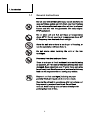
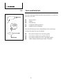
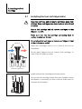
Solarlink GmbH
Drangstedter Str. 37
D 27624 Bad Bederkesa
GERMANY
mail: [email protected]
web: www.solarlink.de
Installation Manual
for RVs IM1
1600 | 1200 | 600
Automatic Charge Control
GB
Thank you for purchasing an EFOY product. We hope that
you will enjoy your new unit.
Please read these instructions first before using and
always keep them nearby. Be sure to follow all directions
in the instructions and in this installation manual.
Should you nevertheless have any questions about
installation or operation, please consult your dealer or the
EFOY hotline.
SFC Smart Fuel Cell AG
Eugen-Sänger-Ring 4
D-85649 Brunnthal-Nord
Hotline: 0049 89 607 454-99
[email protected]
IM1-GB-060421 Installation Manual for RVs IM1
www.efoy.com
1. Introduction
1.
Introduction
1.1
General Instructions
Do not open unit or fuel cartridges. Do not use force to
open cartridges and do not refill them. Any modifications
to the unit may affect safe operation, will lead to a loss of
license and will void the guarantee. Use only original
EFOY equipment.
Do not store unit and fuel cartridges at temperatures
above 45° C. Do not operate at temperatures above 40°
C. Keep away from heat and direct sunlight.
Store the unit where there is no danger of freezing, or
use the automatic antifreeze feature.
Do not smoke when handling the unit or the fuel
cartridges.
Keep away from heat and open flame.
There is a danger of fire if methanol leaks out following
an accident, or if the unit or the fuel cartridge has been
damaged. Keep away from open fire and make sure area
is well ventilated. Small amounts of methanol which may
leak out will evaporate without leaving any residue.
Keep unit and fuel cartridges (including empty or
partially filled cartridges) out of children’s reach.
Operate the unit only in accordance with instructions and
keep operating area well ventilated. Do not block
exhaust. Avoid inhaling exhaust fumes directly or for
prolonged periods of time.
4
1. Introduction
Installation should be carried out by trained personnel
only. Wear proper work clothes. Avoid flowing garments
and wear a hair net if you have long hair. Clothing and hair
can get caught in moving or rotating parts such as in a
drill.
Be sure to leave enough space behind the installation area
when drilling or cutting out openings. Also be sure to
follow the tool manufacturer’s safety instructions.
Solvents used in sealants may emit fumes. Make sure that
there is sufficient ventilation and follow the instructions
for the sealing compound.
Electrical installation work should be done by a licensed
electrician only.
All electrical lines must be adequately insulated and
protected with proper fuses.
Bare wires and contacts are not permitted.
Use the wire harness (included) to connect the unit.
Check the polarity (see illustration) before connecting the
unit.
Both sensor and power lines must always be connected.
Always use separate lines for charging and for voltage
metering to the battery. Otherwise, the flow of current will
cause false readings.
5
1. Introduction
1.2
Tools and Materials
You will need the following tools and sealants to install the
fuel cell in an RV:
electric drill
jigsaw
screwdriver
hexagonal (Allen) wrench
sealant such as Sikaflex
Use the following screws, depending on the mounting
surface (screws are not included):
8 screws to attach the mounting plate
4 screws to attach the remote control
4 screws to attach the fuel-cartridge holder
cable clamps and fixing screws, if needed
6
Table of Content
1. Introduction
4
1.1
General Instructions
4
1.2
Tools and Materials
6
2. Installing the Unit
8
2.1
Standard Equipment
8
2.2
Locations
9
2.3
Notes on choosing a location
9
2.4
Securing the Unit
11
2.5
Off-heat duct
12
2.6
Connecting the Exhaust Hose
14
3. Mounting the Remote Control
15
3.1
Mounting the Remote Control
15
3.2
Connecting the Remote Control
16
4. Electrical Connections
4.1
Electrical Connections
17
17
4.1.1 Connection via the Central Electrical Box (EBL)
18
4.1.2 Connection directly to the battery
20
5. Installing the Fuel Cartridge
22
5.1
Installing the fuel-cartridge holder
22
5.2
Connecting the Fuel Cartridge
23
6. Notes
23
7
2. Installing the Unit
2.
Installing the Unit
2.1
Standard Equipment
Standard Equipment:
Unit
Remote control with data line
RC1
Unit
Remote control with data line RC1
Fuel-cartridge holder with belt FH1
Mounting plate with belt MP1
Exhaust hose (1.5 m) EH1
Off-heat duct (consists of off-heat flange, off-heat bow,
off-heat tube, orifice and fixing screws) OD1
Service kit (G-fuse 250V 8A m, 5 x 20 mm and service
fluid)
User manual UM1
Charge line for RVs CL2
Fuel-cartridge holder with
belt
FH1
Connecting line to fuel-cell 1m
Mounting plate with belt MP1
Eexhaust hose EH1
Battery fuse power 7.5A
Battery fuse sense 2A
Off-heat duct OD1
Service kit
Standard equipment
Extension power line 8m
CL2 charge line for RVs
8
Extension sense line 8m
2. Installing the Unit
2.2
Locations
2
3
1
Ideas for installation:
1
2
3
2.3
false floor or side compartment
seat bench
rear storage area
Notes on choosing a location
Make sure when choosing a location, that
temperature ranges between –20° C and +40° C.
the
This unit generates heat, thus requiring ventilation.
Please take this into account when considering possible
locations.
Provide for a vent opening measuring at least 10 cm
across when installing. Use the off-heat duct (included)
to remove warm air.
min.
Zuluft
cooling
10 cm
air
9
2. Installing the Unit
Install only in upright position. Use the mounting plate
(included).
Make sure that the device does not exceed the maximum
inclination.
Inclination
along
continual:
temporary (<10min):
the
35°
45°
direct
axis:
Inclination along the quadrature axis:
continual:
20°
All electrical connections, the fill opening for service
fluid and the fuel cartridge should be easily accessible.
max. 30 cm
Make sure that the fuel cartridge is located within reach
of the connecting hose (30 cm) and that the hose is
neither kinked nor crushed.
The fuel-cartridge hose and the exhaust hose may not be
damaged. Do not substitute another hose for either of the
two.
Use only original-equipment EFOY hoses.
10
2. Installing the Unit
2.4
Securing the Unit
1. Run the belt in the groove under the mounting plate.
2. Secure the mounting plate tightly to the desired
location. Use eight proper screws and dowels, if
necessary, so that the mounting plate cannot shake
loose in case of an accident.
3. Place the unit onto the mounting plate.
4. Strap the unit tightly to the mounting plate.
11
2. Installing the Unit
2.5
Off-heat duct
The off-heat duct (included) extracts warm air so that the
unit can also be operated in close quarters.
Use the bow to conduct warm air to the side.
cooling
air Zuluft
If you do not need the off-heat bow, you can disconnect it
from the off-heat flange and connect the off-heat tube
directly to the flange.
exhaust
warm
air
Abluft erwärmte
Kühlluft
Make sure that the off-heat tube is not kinked; use a
second bow if needed.
warm air
cooling ø min.
Zuluft
10 cm
air
erwärmte
Kühlluft
Abluft
exhaust
Sink the screws for the off-heat flange into the holes
provided.
Then pass the off-heat tube to the exterior. You will need
an opening with a 100 mm diameter.
Be careful of electrical lines when drilling. The RV
manufacturer or your dealer can provide information as to
the location of lines.
10 cm
12
2. Installing the Unit
Pass the off-heat tube through the opening; any excess
may be shortened.
It may be necessary to use an external face plate to protect
the outlet. Use a suitable sealant to prevent moisture from
penetrating into the body or into the interior.
13
2. Installing the Unit
2.6
Connecting the Exhaust Hose
Exhaust gasses contain moisture and may exceed 60°
C, causing scalding. Exhaust byproducts may contain
injurious substances. Avoid inhaling exhaust directly
or for long periods of time.
The exhaust hose may not be longer than 50 cm in
order to prevent freezing in winter. The hose may be
up to 150 cm long for summer operation and during
transitional seasons.
At no time may siphoning occur in the hose. Make
sure that the hose is neither clogged nor blocked.
Routing the exhaust hose
Up
Down
Avoid siphoning
Remove the cap from the exhaust port. Retain the
cap for winter storage or for possible returns.
Attach the exhaust hose (included) to the exhaust
port.
1 cm
Route the hose to the exterior and use a suitable
sealant to seal the opening. The hose may be
shortened as needed. The opening must be10 mm
in diameter.
Make sure the exhaust hose has no kinks or
blockage and that exhaust can escape freely.
14
3. Mounting the Remote
Control
3.
Mounting the Remote Control
3.1
Mounting the Remote Control
The remote control (1) displays the current status and is
used to control the device. Mount the panel where it is
easily accessible such as in the cockpit.
1
If installing the panel flush with the surface of the unit,
make sure that there is a sufficient opening for the
electronic components behind the opening.
2
3
4
Flush mounting:
1 remote control
2 opening
3 frame
4 screws
1
Surface mounting
2
Secure the surface mount with two screws.
Connect the remote control with the DL 1 data line
(included).
3
4
Then secure the control panel (1) with four suitable
screws (4) and place the frame (3) over the control panel.
Surface mounting:
1 remote control
2 surface mount
3 frame
4 screws
15
3. Mounting the Remote
Control
3.2
Connecting the Remote Control
Connect the remote control with the DL data line
(included).
If the DL 1 data line is not long enough, you can replace it
with a commercially available network line that is longer
or shorter (Category 5 patch cable).
Then insert the plug into the left socket on the unit
marked “Remote Control“.
16
4. Electrical Connections
4.
Electrical Connections
4.1
Electrical Connections
All work should be carried out by qualified technicians in
accordance with technical regulations.
Improper connections or the use of wrong gauge wires
could result in fire.
All wires must be properly insulated and have adequate
voltage rating. All connections must be tight. The use of
uninsulated wires and contacts is not permitted.
The charging lines consists of four leads that must be
connected to the battery as follows:
Power lead:
This lead carries current from the fuel cell to the battery.
Sensor lead:
This lead measures battery voltage.
Power lead
Sensor lead
To minimize current loss in the leads, the following cross
section is recommended, should the battery charging
cable be insufficient:
Length [m]
min. cross section
<5m
5 – 10 m
10 – 15 m
2.5 mm²
4 mm²
6 mm²
Two kinds of electrical connection are possible:
via the central electrical box (Chapter 4.1.1)
directly to the battery (Chapter 4.1.2)
17
4. Electrical Connections
4.1.1
Connection via the Central Electrical Box
(EBL)
TV
entertainment
refrigerators
heating
light
Power lead
EBL
Sense lead
18
4. Electrical Connections
red
brown
Fuse 2A
4
1
5
3
2
or
6
7
1.
unit
2.
connecting line to fuel cell
3.
extension sense line (optional)
4.
battery fuse 2 A
5.
battery (a capacity of 40 – 200 Ah is recommended)
6.
extension power line with 2- or 3- pole plug (optional)
7.
Central electrical box (EBL)
19
4. Electrical Connections
4.1.2
Connection directly to the battery
TV
entertainment
light
heating
refrigerators
power lead
sense lead
20
4. Electrical Connections
red
brown
Fuse 2A
1
4
5
3
2
6
Fuse 7.5A
7
1.
unit
2.
connecting line to fuel cell
3.
extension sense line (optional)
4.
battery fuse sense 2 A
5.
battery (a capacity of 40 – 200 Ah is recommended)
6.
extension power line with 3-pole plug (optional)
7.
battery fuse power 7.5 A
21
5. Installing the Fuel
Cartridge
5.
Installing the Fuel Cartridge
5.1
Installing the fuel-cartridge holder
Keep fuel cartridge and all reserve cartridges away from
children. Keep cartridges away from heat and out of direct
sunshine.
Secure fuel cartridge and all reserve cartridges so that
they can not shift.
Make sure that the fuel-cartridge connecting hose is
neither crushed nor kinked.
warm air
Do not place fuel cartridges or reserve cartridges in front
of the air intake or outlet!
Place fuel cartridges next to or in front of the unit as
illustrated.
Do not place objects such as reserve fuel cartridges in
front of the air intake or outlet.
electrical connection
Install unit and fuel cartridge at the same level.
Secure the fuel-cartridge holder with four suitable screws
and dowels, if necessary, so that it will not shake loose in
the case of an accident.
22
5. Installing the Fuel
Cartridge
5.2
Connecting the Fuel Cartridge
For safety’s sake, use only original EFOY fuel cartridges.
Do not smoke while changing the cartridge and avoid open
flames! Do not expose fuel cartridges to temperatures
above 45°C.
Original-equipment EFOY fuel cartridges contain EFOYapproved methanol. Even slight impurities in commercially
available methanol may cause permanent damage to the
unit and may void the guarantee.
1
Place a new sealed original-equipment EFOY fuel
cartridge into the fuel-cartridge holder (1).
Fasten the belt on the fuel-cartridge holder (2). Do not
attach fuel cartridges without a fuel-cartridge holder.
Remove the childproof cap only after placing the
cartridge into the fuel-cartridge holder (3).
Screw the connector onto the new fuel cartridge.
Press reset on the control panel to extinguish the
yellow warning light and the maintenance message.
2
3
6.
Notes
23
6. Notes
24
6. Notes
25
6. Notes
26
efoy.com
©EFOY is a registrated trademark of SFC Smart Fuel Cell AG.