1
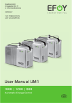
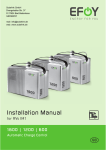
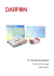
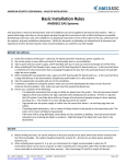
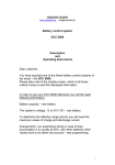
PHOTOVOLTAIK-PHOTOVOLTAIC-PHOTOVOLTAIQUE-FOTOVOLTAICA Solarlink GmbH, Drangstedter Str. 37, D 27624 Bad Bederkesa GERMANY www.solarlink.de [email protected] Operating instructions SolarChargeController 8A/12A/20A/30A UK 716.140|07.50 Contents 1. 2. 3. 4. 5. 6. 7. 8. 9. 10. 11. Safety instructions and exclusion of liability.........................................................2 Charge controller with fuzzy logic........................................................................3 Configuration.......................................................................................................4 Installation............................................................................................................6 Operation.............................................................................................................8 Maintenance.........................................................................................................9 Malfunctions......................................................................................................10 Legal Guarantee.................................................................................................10 Technical data.....................................................................................................11 Protective functions of the controller.................................................................11 Charge controller schematic diagram.................................................................12 1. Safety instructions and exclusion of liability 1.1.Safety instructions are identified as follows: • In this manual, safety instructions for personal safety are identified with this symbol. • Instructions which relate to the functional safety of the system are in bold type. 1.2.General safety instructions For your own safety, the following points must be observed during installation: • When laying cables, ensure that no damage occurs to any of the constructional fire safety measures present in the building. There are more detailed instructions in 4.4. “System wiring”. • The PV components may not be installed and operated in rooms where highly flammable mixtures, e.g. from gas bottles, paint, lacquer, solvents etc., may be present! • Do not store any of the mentioned mixtures in rooms in where PV components are installed! • Avoid sparking when working on the system! • Solar modules generate electricity under incident light. The full voltage is present, even when the incident light levels are low. Work carefully and observe the appropriate safety precautions. • During assembly and electrical connection in the DC circuit of the photovoltaic system, voltages of up to 50 V may occur. You should therefore never touch nonisolated conductor ends! Use well isolated tools only! • Do not use measurement equipment you know to be damaged or defective! The charge controller‘s constructive protective measures can deteriorate if the extension module is not operated as specified by the manufacturer. • Factory labels and markings may not be altered, removed or rendered unreadable. • Impeding the factory-installed ventilation may result in overheating and failure of the device. Do not cover ventilation openings and cooling elements. • All work must be carried out in accordance with the national and local electrical regulations! • If the device is installed abroad, information on rules and protective measures must be obtained via the corresponding institutions/authorities. • Keep children away from the PV system! 1.3. About this manual This manual describes the functions and installation of a solar charge controller in a PV system with battery bank. The corresponding manufacturer‘s installation manual must be observed when installing the remaining components, e.g. solar modules and battery bank. Before you start work, please read: • “Assembling the charge controller“, sections 4.1 - 4.4 • Before assembly, ensure that all preparatory measures have been taken. • Do not start assembly until you are sure that you have understood the technical details in the manual. • Perform the work only in the order prescribed by this manual! • The manual must also be available to third parties for all work performed on the system. • This manual is a component of the charge controller and must be included with it when sold on. 1.4.Exclusion of liability The manufacturer cannot monitor the compliance to this manual as well as the conditions and methods during the installation, operation, usage and maintenance of the charge controller. Improper installation of the system may result in damage to property and, as a result, to bodily injury. Therefore, we assume no responsibility and liability for loss, damage or costs which result or are in any way related to incorrect installation, improper operation and incorrect use and maintenance. Similarly, we assume no responsibility for patent right or other right infringements of third parties caused by usage of this charge controller. The manufacturer reserves the right to make changes to the product, technical data or assembly and operating instructions without prior notice. 2. Charge controller with fuzzy logic 2.1.Overall function of the charge controller in the PV system The charge controller is used in PV power supplies with battery bank for the hobby and leisure, residential, business, commercial and small company areas. The charge controller monitors the charge status of the battery, controls the charging process and the connection/disconnection of the loads. This allows the battery use to be optimised and its service life to be significantly extended. The charge controller is set for lead batteries with liquid electrolyte on delivery and can be switched to a setting for batteries with solid electrolyte. The charge controller can be used for all solar modules to the maximum connection value of the module short circuit current. 2.2.Monitoring and control functions • SOC calculation Using a special new algorithm, the controller can „learn“ the characteristic curve of the battery. After this learning phase, the SOC charge status of the battery is indicated with an average precision of approx. 90 %. This charge status is the basis for most control and monitoring functions. • Overcharge protection Frequent overcharging damages the battery bank. The charging process and the overcharge protection are therefore controlled by a new hybrid actuator with pulse-width modulation to guarantee gentle charging of the battery. • Voltage recognition A special measurement process renders battery sensor lines. The voltage drop on the battery line is compensated out after the first full charge. LED 1 (Info) for operating status and fault messages LED 2 (Battery) for charge status, load shedding and early warning Plug-in fuse: 8 A controller: 10 A 12 A controller:15 A 20 A controller: 20 A Integrated temperature sensor Connection terminals 30 A controller: 30 A Figure 1 •Cyclicalcharging(leadandgel) Thechargecontrollerraisestheend-of-chargevoltageforapprox.1hourforthenext chargingcycleaftertheSOCfallsbelow70%(12.4V). •Equalizingcharge(leadonly) Whenthechargestatus(SOC)fallsbelow40%(11,7V)equalizingchargingisactivated.Duringthisstage,theend-of-chargevoltageisraisedforapprox.1hour;theelectrolytewhichpreventsacidstratificationismixedandthusextendstheservicelifeof thebatterybank.Thisequalizesallcellsandextendstheservicelifeofthebatterybank. •Monthlycharging Dependingonthesetting(leadorgel),thecorrespondingincreaseoftheend-of-charge voltageismaintainedover1hourevery30days. •Temperaturetrackingoftheend-of-chargevoltage Asthebatterytemperatureincreases,theoptimumend-of-chargevoltageoflead-acid batteriesdecreases.Athighbatterytemperatures,aconstantlysetend-of-charge voltageleadstouncontrolledgassing.Temperaturetrackingreducestheend-of-charge voltageathightemperaturesandraisesthematlowtemperatures.Temperaturetrackingwiththesensorintegratedinthesolarchargecontrolleralsofunctionsforcyclical chargingandequalizingcharging.Theend-of-chargevoltageisneverraisedabove15V inordertoprotecttheloads(e.g.equalizingchargingatlowtemperatures). •Display TwoLEDsprovideinformationontheoperationmodeofyourPVsystem.LED1(Info LED)showsthecontrollerstatus,LED2(BatteryLED)showsthebatterystatus. •Deepdischargeprotection Deepdischargecausesyourbatterytolosecapacityduetosulphation.Thecharge controllerdeepdischargeprotectordisconnectstheloadsatSOC<30%(11.1V).The loadsareautomaticallyreconnectedatachargestatusof50%. 3. Configuration 3.1.Adjustingthechargecontroller Thesolarchargecontrollerautomaticallyadjuststothesystemvoltage(12V/24V) whenitisinstalled.Thecontrollerissetforusewithleadbatterieswithcurrentcharge statuscalculationondelivery.Thismustonlybechangedinthefollowingcases: •Directconnectionofamainloadtothebattery(see3.3) •Useofagelbattery(see3.4) •Activationofthenightlightfunction(see3.5) Thechargecontrollerissetusingshortcircuitplugs(“jumpers”)whichconnecttwo adjacentcontactpinstooneanother.TheseareatthetopleftofthePCB.(Figure2) Figure2:Jumper 4 3.2 Basic setting Equalization charging is activated in the charge controller on delivery, i.e. it is optimised for batteries with liquid electrolyte. Equalization charging is generally deactivated for batteries with solid electrolyte. Follow the instructions of the battery manufacturer! 2 4 6 8 10 black blue red 1 3 5 7 9 Basic setting 3.3 Direct connection to the battery If other chargers or an inverter are connected to the battery, the charge status is no longer displayed correctly. The controller can be switched to voltage-controlled regulation, just like standard products. After this is changed, only the battery voltage is evaluated to determine the charge status. All functions are activated via voltage levels, including the charge status display. LEDred = 10.8 V LEDyellow = 12.0 V LEDgreen = 13.2 V The charge status LED functions as a colour multimeter in this setting. 2 4 6 8 10 1 Direct connection to the battery 3 5 7 9 2 4 6 1 3 5 Tip: For storage, connect jumpers which are not required to one pin only. Change the red jumper from 7/8 to 5/6. The blue jumper on 4/6 cannot stay in the factory setting and must be repositioned as described in the “Selecting the battery” paragraph. 3.4 Selecting the battery The following jumper settings are required depending on the battery used and the charge controller: Lead battery SOC setting Voltage setting Gel battery 2 4 6 8 10 1 3 5 7 9 2 4 6 8 10 1 3 5 7 9 2 4 6 8 10 1 3 5 7 9 2 4 6 8 10 1 3 5 7 9 Lead: Position 3/4 may not be occupied. To do so, either remove the blue jumper or place it on 4/6 (factory setting). Gel: When switching to using gel batteries, the blue jumper must be changed from 4/6 to 3/4. 3.5 Night light function If the controller is used in lighting systems, the so-called night light function can be programmed. If this function is activated, all loads are connected at night and disconnected during the day. The deep discharge protector remains activated. Remove the jumper which connects contact pins 1/2 to activate the night light function. Store the short circuit plugs (jumpers) safely so that you can return the controller to the basic setting! 2 4 6 8 10 1 Night light function 3 5 7 9 If you do not wish to attempt to configure the controller yourself, please contact your specialist dealer. No liability can be accepted for damage of any kind caused by an incorrectly set charge controller! 4. Installation 4.1.Choose a suitable location Do not install and operate PV components in rooms where highly flammable gas mixtures can occur! Explosive oxyhydrogen gas can form near the battery. Ensure that the area around the battery is well ventilated and avoid sparking! Observe the regulations for batteries! The following must be observed in particular: • DIN VDE 0510 Part 2, sections - 7 Precautions against explosion hazard - 8 Precautions against dangers from electrolyte - 9 Storage • National Electric Code with article 690 Choose the installation location in accordance with the following criteria: • Protect the charge controller from direct weathering • Avoid direct exposure to sunlight and heating from adjacent devices • Ensure that the device is not subject to dirt or moisture • Install it as close to the battery as possible (safety clearance at least 30 cm) Solar modules Battery Load Figure 3: Overview of connections 4.2.Securing the charge controller When securing the charge controller, ensure that the cooling element is well ventilated: • Install the charge controller so that the cable openings are at the bottom • Ensure that no objects are within the 100 mm clearance space above and below the device • Secure the charge controller appropriately: Mount the charge controller to the wall using the holes in the housing (cooling element) with screws. The charge controller is designed without strain relief, so that the conductor cross-section can be adapted for the local conditions. For this reason, strain relief (e.g. cable clips) must be put in place approx. 100 mm below the controller before the cable looms can be distributed to the individual components. 4.3.Preparing the wiring Ensure that the diameter of the wires matches the power output of the controller. The values of the following table specify the minimum cross-sections required from the controller to the module distributor box (approx. 10 m), to the battery (approx. 2 m) and to the load distributor socket (approx. 5 m): Controller Load Cross-section AWG 8A 8A 6 mm² 10 Isolation 85 °C 12 A 12 A 10 mm² 8 85 °C 20 A 20 A 10 mm² 8 85 °C 30 A 30 A 16 mm² 6 85 °C Before you start wiring ensure that • the batteries to be used are suitable and correctly connected (check the system voltage) • the maximum solar power of the solar generator does not exceed the connection value of the charge controller 4.4. Wiring • Solar modules generate electricity under incident light. The full voltage is present, even when the incident light levels are low. Fasten a lightproof cover securely over the solar modules with adhesive tape. The cover allows the voltage level of the modules to be reduced to zero. The voltage level of the solar modules may never be reduced to zero by short circuiting them. • Use well isolated tools only! • Never touch open conductor ends! • Isolate any unisolated conductor end which is not connected immediately! • Only work when the floor below is dry! The components (solar modules, wires etc.) may not be wet or moist on installation! • Ensure that the polarity is correct when wiring the device! n Grounding The components in stand-alone systems do not have to be grounded – this is not standard practice or may be prohibited by national regulations (e.g.: DIN 57100 Part 410 Prohibition of grounding protective low voltage circuits). See point 10 for further information. n Cutting to size All conductors must be cut to size before connection: • Shortening • Remove isolation on both sides and squeeze core end sleeves open if necessary • Cover the free conductor ends which are not to be connected immediately with isolating tape • Mark the end of each conductor: - Module cable: M+, M- - Battery cable: B+, B- - Load connection cable: L+, L- Connect the module and string cables to the connection sockets of the PV modules only in accordance with the manufacturer’s instructions. Wire the device in the following order to avoid malfunctions: Battery Modules Load n Connecting the battery bank to the charge controller • Remove the fuse in the controller • Wire the battery connection cable (A+, A-) in parallel between the charge controller and the battery bank. • Connect the battery connection cable to the terminal pair of the charge controller. Ensure that the polarity is correct. • Fit holders for external (floating) fuses* to the battery connection cable close to the battery pole: 8 A controller: 10 A 12 A controller: 15 A 20 A controller: 20 A 30 A controller: 30 A Do not insert the fuse yet. • Connect battery connection cable A+ to the plus pole of the battery. • Connect battery connection cable A- to the minus pole of the battery. • Insert the fuse *) Not included n Connecting the solar generator to the charge controller • Connect the module connection (M+, M-) to the screw-type terminals of the charge controller. Ensure that the polarity is correct. • Only connect solar generators as energy sources (no power supply units, diesel or wind generators). n Connect the loads • Protect every load circuit with a fuse. • Disconnect all loads before connecting the load conductor (remove the fuse) to prevent sparking. • Connect the load conductor to the screw-type terminals of the charge controller. Ensure that the polarity is correct! Connect loads, which may not be switched off by the charge controller shedding the load, e.g. emergency light, radio connection, directly to the battery! This increases the risk of deep discharge, which is no longer controlled by the charge controller! Protect these loads with a separate fuse. Then secure all cables with strain relief in the immediate vicinity of the charge controller. Fit strain relief for the other components also. 5. Operation 5.1. Testing and commissioning Check the following items after wiring: • Correct polarity at all connections (cable labels), • Secure fit of all cable connections, • Correct function of all strain relief fittings • Parallel wiring of the battery connection cables • Tightness of all screw and terminal connections Starting the system: Insert the fuses at the charge controller and battery and wait until the left LED flashes green (after 2 min at latest) Remove the cover of the solar generator. The loads only work when the right LED lights permanently or flashes rapidly. 5.2. LED operating status displays • Charge status display (SOC) The colour of the right LED indicates the charge status of the battery. The colour changes in ten steps from red (approx. 0 % charge status) to yellow (approx. 50 %) to green (approx. 100 %). •Deep discharge warning When the charge status falls below 40 %, the right LED flashes rapidly (10 x faster than the left LED) to warn the user of the risk of load deactivation. • Deep discharge deactivation The right LED flashes slowly (approximately the same frequency as the Info LED) to indicate that the deep discharge protector has deactivated the load. The device is disconnected when the charge status reaches 30 % (LED lights red/yellow). The load is automatically reconnected when the SOC reaches 50 % (LED lights yellow). The charge status can also be identified based on the colour while the LED is flashing. • Information LED The information LED flashes green during normal operation. A red colour indicates that there is a fault. The fault can be determined using the table. Fault description Controller protective measures Info LED Reset Normal operation Surge current load Everything OK None Load deactivated Green flashing Red-green flashing No reset Too much load current Surge current module Module current too high Load deactivated Red-yellow flashing Overheating Controller overheated Load deactivated Steady red light Switch off or disconnect load 1); rectify fault reactivate Automatic, when surge current no longer present Automatic, when temperature drops 2) Battery overload Battery voltage too high Load deactivated; module shortcircuited Yellow flashing Automatic, when voltage drops 3) Internal temp. 85 °C 15 V / 30 V Battery voltage too low Battery voltage too low; no battery; faulty fuse No battery connected; fuse faulty Load deactivated Red flashing Automatic, when voltage increases 10,5 V / 21 V Load deactivated Both LEDs steady red Disconnect solar generator and replace fuse (see chap. 7.1) Open-circuit operation Technical data 110 % 110 % 1) The surge current deactivators are emergency functions which protect the controller from irreparable damage. When sizing the system, ensure that the max. module and load currents permitted are not exceeded. 2) If the controller overheats, check whether the device is sufficiently cooled and ventilated at the installation location. 3) The most common causes of battery overloading are charge sources connected directly to the battery. As a precaution, loads are switched off, as they are often irreparably damaged by excessive voltage! 6. Maintenance The charge controller is maintenance-free. Inspect the entire PV installation at least once a year in accordance with the manufacturer‘s specifications. • Dust controller and cooling element and ensure that the cooling element is sufficiently ventilated • Check all strain relief fittings • Ensure that all cable connections are securely fastened • Tighten screws if necessary 7. Malfunctions A range of measures protect the charge controller from irreparable damage. In spite of this, you must take great care to ensure that the charge controller is used properly. Some malfunctions are indicated via the information LED. However, only faults for which the system is properly installed can be displayed. If faults other than those described occur, first check whether the controller is connected to the battery, the module and the loads with the correct polarity. Then check whether the fuse is faulty. The controller automatically switches off the load when faults occur. 7.1. Changing fuses Follow these steps in the correct order to change a fuse: Disconnect the solar generator (minus connection) from the solar charge controller. Remove the faulty fuse and insert a new one (the left LED flashes green) Reconnect the solar generator to the solar charge controller 7.2.Starting after open-circuit operation If the battery is not connected to the controller (open-circuit operation, fuse faulty, battery connection interrupted) and the solar module supplies more power than the load requires, both LEDs light red. If the solar power generated is less than the consumption, the load is activated periodically. At night, both LEDs are switched off. The controller is protected against open-circuit operation. However, to guarantee safe start-up after this open-circuit operation, the following steps are absolutely necessary: Disconnect the solar generator (minus connection) from the solar charge controller. Remove the fuse and insert it again (restart) Connect the solar generator again 8. Legal Guarantee In accordance with German statutory regulations, there is a 2-year legal guarantee on this product for the customer. The seller will remove all manufacturing and material faults that occur in the product during the legal guarantee period and affect the correct functioning of the product. Natural wear and tear does not constitute a malfunction. Legal guarantee does not apply if the fault can be attributed to third parties, unprofessional installation or commissioning, incorrect or negligent handling, improper transport, excessive loading, use of improper equipment, faulty construction work, unsuitable construction location or improper operation or use. Legal guarantee claims shall only be accepted if notification of the fault is provided immediately after it is discovered. Legal guarantee claims are to be directed to the seller. The seller must be informed before legal guarantee claims are processed. For processing a legal guarantee claim an exact fault description and the invoice / delivery note must be provided. The seller can choose to fulfil the legal guarantee either by repair or replacement. If the product can neither be repaired nor replaced, or if this does not occur within a suitable period in spite of the specification of an extension period in writing by the customer, the reduction in value caused by the fault shall be replaced, or, if this is not sufficient taking the interests of the end customer into consideration, the contract is cancelled. Any further claims against the seller based on this legal guarantee obligation, in particular claims for damages due to lost profit, loss-of-use or indirect damages are excluded, unless liability is obligatory by German law. 10 9. Technical data Charge controller type 8A 12 A 20 A 30 A Max. module short-circuit current at 50 °C 8A 12 A 20 A 30 A Max. load current at 50 °C 8A 12 A 20 A 30 A Terminal clamps (fine-wire/single wire) 16/25 mm² = 4/6 AWB Weight 420 g Measurements 188 x 106 x 49 Protection class IP 22 System voltage 12 V / 24 V Permitted ambient temperature -25 °C...+50 °C AtonIC Algorithm data: SOC oriented: Voltage oriented: Deep discharge warning SOC < 40 % 11,7 V Load shedding SOC < 30 % 11,1 V Shift-in SOC > 50 % 12,6 V Equalization loading (14.7 V) SOC < 40 % 11,7 V Cyclical loading (14.4 V) SOC < 70 % 12,4 V End-of-charge voltage Temperature compensation 13,7 V 13,7 V -4 mV/K/cell -4 mV/K/cell The voltage must be doubled when used in 24 V systems! 10.Protective functions of the controller The solar controller has the following protective functions: • Short circuit at the module. Electronically protected. The charging process is automatically interrupted. Measures: Connect the module correctly. The controller automatically continues to work. • Incorrect polarity of the battery. Plug-in fuse is triggered. Measures: Connect the battery with correct polarity. Replace the plug-in fuse, see 7.1. • Short circuit at the load output and/or surge current. Electronically protected. Information display flashes red-green (see 5.2). Measures: Disconnect the load cable and wait until the information display switches from red-green to green flashing. Reconnect the load cable. • Surge current, overheating, overload of the module. Electronically protected. Load is deactivated automatically. Measures: Wait until a permitted operating status has returned. The controller automatically reactivates the load. • Undervoltage. Electronically protected. Load is deactivated automatically. Measures: Wait until the battery is sufficiently recharged. The controller automatically reactivates the load. • Operation without battery. Electronically protected. The controller is protected, its functions are limited. Measures: see 7.2. • Incorrect polarity of a module. Electronically protected. The charging process is automatically interrupted. Measures: Connect the module correctly. 11 11.Charge controller schematic diagram The following sections only describe the technical grounding options. The goal is to maintain the controller functions. The installing engineer must note and observe the national regulations in the region of use. The loss of the protective low voltage status caused by grounding must be compensated by corresponding isolation measures for live parts (protection against direct contact). If the plus side is selected for grounding, it can also be used as an earth for all system components. All plus conductors are internally interconnected in any case. Only one connection can be grounded from the minus connections of the module, battery and load components. If your solar system already provides a minus-side earth, only one component (in this example, battery-minus) may be connected to this earth. Connecting to other minus connections (module or load) bridges control elements and the fuse. This causes malfunctions or even irreparable damage to the controller. In systems with preset load–minus–earth (e.g. grounding antennas) all other components must be floating. 12