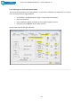
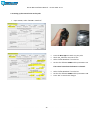
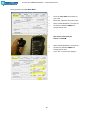
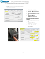
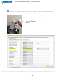
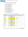
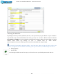
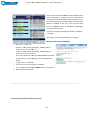
1
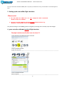
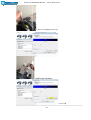
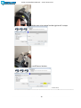
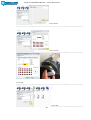
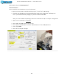
INSTALLATION MANUAL FOR USING YOUR THROTTLE
®
WITH
17. Dezember 2014 www.cockpitforyou.com –
Torsten Müller translation, layout, design by Patrick
Messerschmitt
Prosim 737 In
nstallation Manual - version 2014-12-17
Installation manual for using your TQ with ProSim
m737®
Thank you for purchasing the mo
otorized version of our new COCKPITFORYOU 737
73 throttle quadrant. It has
been assembled and tested with the greatest care. To make the installation as convenient
c
as possible for
you, we tried to describe the installati
stallation process in great detail. Should you still experience
e
difficulties with
the setup or operation of your throttle
thro
quadrant, please do not hesitate to conttact us via email or phone.
In the near future we will release
lease a video setup tutorial in addition to this manual that
t
will guide you through
all the necessary steps.
We hope you will have as much
ch fun
f flying your new TQ as we had engineering an
nd assembling it.
1. Before getting started
rted
The motor functions of your thro
ottle are realized in connection with an Opencockpi
ckpits DC Motor Interface
card. In order to have it commun
unicate with Prosim and Flight Simulator you need
ed to
•
download and install a copyy of SIOC by Opencockpits, if you haven’t already..
It is available for download here:
ere:
http://www.opencockpits.com/iindex.php/en/download/category/sioc
SIOC ver 5.0B5 is the latest versio
on upon release of this manual and was confirmeed working with our
throttle quadrant.
During the setup of your
y
TQ, the use of Microsoft’s standard B737 is recommended.
r
Please make sure that no other programs are running while install
stalling SIOC.
2
Prosim 737 In
nstallation Manual - version 2014-12-17
2. Connecting your Th
hrottle
Your motorized throttle comes with 2 USB cables and 2 independent
power lines and is running on 12
2 V DC. The use of a common computer
PSU (power supply unit) is reccommended, since they deliver stable
power, can connect many other devices and most home cockpit builders
have these units on spare anywa
way. You may however use any other 12
volt DC power supply with at leasst 5 amps.
USB cable 1: connects to a Bodna
dnar® card, which connects all the axis, buttons and
a switches. Just like your
regular joystick, this cable should
ld be connected to your computer running Flight Simulator.
S
The card is plugand-play and should not require
ire any further installation. It can be found in you
ur list of game controllers
under “BU0836X Interface”.
USB cable 2: connects an Openccockpits® DC Motor card. This should be connecteed to the computer where
you would like to run your instance
stance of the SIOC software. It can be hooked up to
o your FS computer as well
as it could run on any other mach
hine in your network.
Please note that the carrd is only detected by SIOC when the power has been connected properly.
Additional hint: If you have not
ot yet connected your power, the cable that is imme
mediately detected by your
computer belongs to the bodnar card.
Connecting 12 V DC to your thro
ottle quadrant
Powerline 1 – Motors
Depending on what versi
ersion of the TQ you have received, you already have
h
a standard PC power
supply adapter for easy connection with a common 12v computer PSU. (not included) This will
power the motors of the throttle and the Opencockpits DC Motor Card.
Please make sure that (+) and (-) are connected properly to your PSU. Usu
sually, 12v (+) is supplied by
the yellow wire. (-) conn
onnects to the common black wire of the PSU. If in doubt, verify the correct
output with a Voltmeter
ter before connecting your throttle. Any other vo
oltage may damage your
throttle!
Powerline 2 - Backlightin
ng
The power supply for the backlighting is running on 12 V as wellll and can be connected
independently of the mo
otor power, allowing users to control it separattely. For example, a relais
card could switch on the backlighting, every time power is available via th
he aircraft’s systems.
The black wire is commo
on ( - ), the red wire is plus (+).
3
Prosim 737 In
nstallation Manual - version 2014-12-17
Once you have SIOC installed and the power is properly connected to the TQ, the DC motor
m
card should appear in
SIOC.
3. Setting up the axis with
hin flight simulator
Please note:
1. The SPD BRK and FLAP lever are only configured within ProSim
m737!
Neither in FSX, nor in FSU
UIPC!
2. The game controller MUSST be calibrated outside of flight simulator (e.g.
Windows / control paneel / Game controller)
The yellow markings in the following
wing pictures will guide you through the necessarry steps and changes.
4. game controller calibrateed outside of flight simulator
The flight simulator and ProSim must be closed !!!
• open Windows/control panel/Game controller
• Select “BU0836X
BU0836X Interface”
Interface
• right click Properties
------------------------------------------------------------------------------------------------------------------------------------------------------------------------------------------------------------------------------------
• Select “BU0836X Interface
terface”
• Press Properties
-------------------------------------------------------------------------------------------------------------------------------------------------------------------------------------------------------------------------------------------------------------------------
4
Prosim 737 In
nstallation Manual - version 2014-12-17
• Select properties
------------------------------------------------------------------------------------------------------------------------------------------------------------------------------------------------------------------------------------------------
• Select Calibrate
-------------------------------------------------------------------------------------------------------------------------------------------------------------------------------------------------------------------------------------------------------------------------
• select Next
---------------------------------------------------------------------------------------------------------------------------------------------------------------------------------------------------------------------------------------------------5
Prosim 737 In
nstallation Manual - version 2014-12-17
-------------------------------------------------------------------------------------------------------
• Move thrust lever 1 and 2 to full thrust,
• and Press a button.
------------------------------------------------------------------------------------------------------6
Prosim 737 In
nstallation Manual - version 2014-12-17
• Make sure thrust levers 1 and 2 to are in their idle position,
• and Press a button.
• select Next
---------------------------------------------------------------------------------------------------------------------------------------------------------------------------------------------------------------------------------------------------------------------------------------------------------------------------------------------------------------------------------------------
7
Prosim 737 In
nstallation Manual - version 2014-12-17
• Make sure thrust levers 1 and 2 middle position
• and Press a button.
• select Next
------------------------------------------------------------------------------------------------------------------------------------------------------------------------------------------------------------------------------------------------------------------------
8
Prosim 737 In
nstallation Manual - version 2014-12-17
• Make sure Reverser 1 full position,
• and Press a button.
------------------------------------------------------------------------------------------------------------------------------------------------------------------------------------9
Prosim 737 In
nstallation Manual - version 2014-12-17
• Make sure Reverser 1 idle position,
• and Press a button.
• select Next
-----------------------------------------------------------------------------------------------------------------------------------------------------------------------------------------------------------------------------------------------------------------
10
Prosim 737 In
nstallation Manual - version 2014-12-17
• Make sure Reverser 2 full position,
• and Press a button.
-----------------------------------------------------------------------------------------------------------------------------------------------------------------------------------------------------------------------------------------------------------------
11
Prosim 737 In
nstallation Manual - version 2014-12-17
• Make sure Reverser 2 idle position,
• and Press a button.
• select Next
------------------------------------------------------------------------------------------------------12
Prosim 737 In
nstallation Manual - version 2014-12-17
• Make sure SPD BRK position at the white stop at the front,
• and Press a button.
------------------------------------------------------------------------------------------------------------------------------------------------------------------------------------------------------------13
Prosim 737 In
nstallation Manual - version 2014-12-17
• Make sure SPD BRK position UP,
• and Press a button.
• select Next
------------------------------------------------------------------------------------------------------14
Prosim 737 In
nstallation Manual - version 2014-12-17
Make sure Flap position 0 UP,
• and Press a button.
-------------------------------------------------------------------------------------------------------
15
Prosim 737 In
nstallation Manual - version 2014-12-17
Make sure Flap position 40 Down,
• and Press a button.
• select Next
-------------------------------------------------------------------------------------------------------------------------------------------------------------------------------------16
Prosim 737 In
nstallation Manual - version 2014-12-17
•Make sure trim wheel to the left until it stops
• and Press a button.
---------------------------------------------------------------------------------------------------------------------------------------------------------------------------------------------------17
Prosim 737 In
nstallation Manual - version 2014-12-17
•Make sure trim wheel to the right until it stops
• and Press a button.
• select Next
-------------------------------------------------------------------------------------------------------
18
Prosim 737 In
nstallation Manual - version 2014-12-17
• select Finish
-----------------------------------------------------------------------------------------------------------------------------------------------------------------------------------------------------------------------------------------
• select assume
-----------------------------------------------------------------------------------------------------------------------------------------------------------------------------------------------------------------------------------------------------------------
• Bring the Trim axis to the center position
positio !
• select OK
-----------------------------------------------------------------------------------------------------------------------------------------------------------------------------------------------------------------------------------------------------------------
• select OK
-------------------------------------------------------------------------------------------------------------------------------------------------------------------------------------------------------------------------------------19
Prosim 737 In
nstallation Manual - version 2014-12-17
Note: The button numbers can va
ary, please do not pay attention to them.
The yellow markings in the following
wing pictures will guide you through the necessarry steps and changes.
Attention !! We recommend the best current file "FSUIPC.ini"
FSUIPC.ini" to
delete and re-start FS.
FS
As often old settings are still saved in the FSIOPC.ini.
FSIOPC.ini (old TQ or
similar)
If you do not know how to do this,
this contact us !!
5. Axis Configuration in FSUIPC
Open FSUIPC and go to “Axiss Assignment”.
5.1. thrust levers 1
First we need the trim thrust levers 1 axis to be detected.
•
•
Move yourr thrust levers 1 until
u
the numbers under “In” and “Out” start
tart moving.
If another axis is blocking
cking you from seeing the thust lervers, press “Ign
gnore Axis” and keep lever
move. If you still don
n’t see any changes, try “Rescan” and move the lever.
leve
After you see the num
mbers responding to the move the thrust levers 1,
1 it is ready for
configuration.
•
Make sure the “Raw”
w” box is unchecked
•
•
•
•
Press “Delta” and maake sure it is set to 1 or 0.
Press “Send to FSUIPC
IPC offset” and select “Offset Word Set” from the dropdown
d
list
Enter Offset x9020
Press “OK” to save yo
our changes
20
Prosim 737 In
nstallation Manual - version 2014-12-17
----------------------------------------------------------------------------------------------------------------------------------------------------------------------------------------------------------------------------------------------------------------------------
21
Prosim 737
7 Installation Manual - version 2014-12-17
Open FSUIPC and go to “Axiss Assignment”.
5.2. thrust levers 2
First we need the trim thrust levers 2 axis to be detected.
•
•
tart moving.
Move yourr thrust levers 2 until the numbers under “In” and “Out” start
If another axis is blocking
cking you from seeing the thust lervers, press “Ign
gnore Axis” and keep lever
move. If you still don
n’t see any changes, try “Rescan” and move the lever.
After you see the num
mbers responding to the move the thrust levers 2,
2 it is ready for configuration.
•
Make sure the “Raw”
w” box is unchecked
•
•
•
•
Press “Delta” and maake sure it is set to 1 or 0.
Press “Send to FSUIPC
IPC offset” and select “Offset Word Set” from the dropdown
d
list
Enter Offset x9045
Press “OK” to save yo
our changes
----------------------------------------------------------------------------------------------------------------------------------------------------------------------------------------------------------------------------------------------------------------
22
Prosim 737 In
nstallation Manual - version 2014-12-17
Open FSUIPC and go to “Axiss Assignment”.
5.3. Trim wheel
First we need the trim wheel
el axis
a to be detected.
•
•
Move your trim wheel until
u
the numbers under “In” and “Out” start moving.
m
If another axis is blocking
cking you from seeing the trim wheel, press “Igno
ore Axis” and keep turning
the wheel. If you still don’t see any changes, try “Rescan” and move the
t wheel.
The trim wheel is only detected
etected by FSUIPC within a certain range. Therefore don’t
d
give up that fast and
keep turning the wheels. If you feel that you are in an upper or lower detent and it is hard to move the trim
wheel, go in the opposite direction
on.
After you see the num
mbers responding to the turning of the wheel, it is ready for configuration.
•
Make sure the “Raw”
w” box is unchecked
•
•
•
•
Press “Delta” and maake sure it is set to 1 or 0.
Press “Send to FSUIPC
IPC offset” and select “Offset Word Set” from the dropdown
d
list
Enter Offset x9300
Press “OK” to save yo
our changes
--------------------------------------------------------------------------------------------------------------------------------------------------------------------------------------------------------------------------------------------------------------------------------------------------------------------------------------------------------------------------------------------------------
23
Prosim 737 Insstallation Manual - version 2014-12-17
5.4. Calibrating your toe brakes within FSUIPC
For the correct operation of the Parking brake, it is necessary to calibrate your To
oe brakes, in case you
have connected them to Flight Siimulator.
•
•
•
•
Go to FSUIPC, Joystick
tick Calibration, page 2 “Prop, mixture and brakes””
Reset the left brake
Set the Minimum detent
de
and make sure the pedal is slightly pressed
Fully push your pedal
al and
a set the “Max” position
Do the same steps for the right toe brake.
----------------------------------------------------------------------------------------------------------------------------------------------------------------------
24
Prosim 737
7 Installation Manual - version 2014-12-17
5.5. Setting up the manual trim on the yoke
•
Open FSUIPC, select “Button
ons + Switches”
•
•
•
•
Press the Nose up trim switch on your yoke
Check the „Selectt for FS control“ box
Select “Offset Wo
ord Set” from the list
Set the first offset
et to x9093 and the parameter to 1
The Control sentt when the button is released:
•
•
•
25
Select “Offset Wo
ord Set” from the list
Set the first offset
et to x9093 and the parameter to 0
Press “OK” to savve these changes
Prosim 737 Installat
tallation Manual - version 2014-12-17
Same procedure for Trim Nose down:
d
•
•
•
•
Press the nose do
own trim switch on
your yoke
Check the “Selectt for FS control“ box
Select “Offset Wo
ord Set” from the list
Set the first offset
et to x9093 and
the parameter to
o2
The Control sent when the
button is released
ed:
•
•
•
26
Select “Offset Wo
ord Set” from the list
Set the first offset
et to x9093 and
the parameter to
o0
Press “OK” to savve these changes
Prosim 737 Installat
tallation Manual - version 2014-12-17
5.6. Assigning the AP disconnectt button in FSUIPC
•
•
•
•
Press the AP disconnect
button
n on your yoke
Check
eck the “Select for FS
contro
ol“ box
Select “Offset Word Set”
from the
t list
Set the first offset to
x9093
93 and the parameter
to 3
The Control
C
sent
when
n the button is
releassed:
•
•
•
Select “Offset Word Set”
from the list
Set the first offset to
x9093
93 and the
param
meter to 0
Press
ress “OK” to save
thes
es changes
ch
-----------------------------------------------------------------------------------------------------------------------------------------------------------------------------------------------------------------------------------------------------------------------------------------------------------------------------------------------------------------------------------------------------------------------
27
Prosim 737 Installat
tallation Manual - version 2014-12-17
5.7. Assigning the Stab trim
im cutout
c
switches in FSUIPC
Assigning the Stab Trim Main Elect
E
Switch in FSUIPC
• Select Buttons + Switches
•
•
•
•
•
Select Button
ns + Switches
press Stab Tri
rim Main Elect
Check the „Sele
Select for FS control“
box
Select “Offset
set Word Set” from the
list
Set the first offset
o
to
x9102 and th
he paramete to 1
The Control sent when the button is
released:
• Select “Offset
set Word Set” from the
list
• Set the first offset
o
to
x9102 and thee parameter to
•
28
Press “OK”
K” to save
thes changes
es
Prosim 737 Installat
tallation Manual - version 2014-12-17
Configuring the Stab Trim Auto Pilot
P
Switch in FSUIPC
ed to “Buttons + Switches”
• Open FSUIPC again and proceed
• Select Buttonss + Switches
• Press Stab Trim Auto Pilot
•
Check the „Sele
Select for FS control“
box
• Select “Offset
set Word Set” from the
list
• Set the first offset
o
to
x9103 and th
he paramete to 1
The Control sent when the button is
released:
• Select “Offset
set Word Set” from the
list
• Set the first offset
o
to
x9103 and thee parameter to 0
•
29
Press “OK”
K” to save
thes changes
es
Prosim 737 Installat
tallation Manual - version 2014-12-17
Configuring the Parking Brake Switch
Sw
in FSUIPC
• Open FSUIPC again and proceed
ed to “Buttons + Switches”
• Select Buttonss + Switches
• Presss Parking Brake
• Select “Offset
set Word Set” from the
list
• Set the first offset
o
to x9168 and
the parameteer to 1
The Control sent when the button is
released:
• Select “Offset
set Word Set” from the
list
• Set the first offset
o
to x9168 and
the parameteer to 0
• Press “OK” to
o save these changes
30
Prosim 737 Installat
tallation Manual - version 2014-12-17
Configuring the Parking Lights Test in FSUIPC
• Open FSUIPC again and proceed
ed to “Buttons + Switches”
• Select Buttonss + Switches
• Presss Lights Test
• Check the „Sele
Select for FS control“
box
• Select “Offset Word Set” from the
list
• Set the first off
ffset to x9091 and
the parameterr to 1
The Control sent when the button is
released:
• Select “Offset
set Word Set” from the
list
• Set the first offset
o
to x9091 and
the parameteer to 0
• Press “OK” to
o save these changes
31
Prosim 737 Installat
tallation Manual - version 2014-12-17
6. Configuration of the
e Throttle Quadrant within Prosim
m737
Now we are almost there – time to setup the axis and switches within Prosim.
Before we proceed, make sure that you have the “Directinput support for joystick
cks”, as well as FSUIPC
support enabled.
32
Prosim 737 Installat
tallation Manual - version 2014-12-17
Make sure the following buttonss are NOT set within Prosim:
33
Prosim 737 Installat
tallation Manual - version 2014-12-17
6.1. Assigning the AP Disconn
onnect button in Prosim737
•
•
•
•
Go to configuration – Swit
witches MCP / Throttle
Select “FSUIPC 8 bit U” from
f
the list
Set Offset “0x9093”
Press “OK” to save thesee changes
34
Prosim 737 Installat
tallation Manual - version 2014-12-17
6.2. Auto Throttle Disconnect Switches
Sw
Assigning one of the AT disconn
onnect buttons once is sufficient. Either of these switches
s
will still
disconnect the autothrottle.
•
•
Go to “Configuration – Switches MCP / Throttle”
Thr
Assign “AT Disengage
Pushed”
---------------------------------------------------------------------------------------------------------------------------------------------------------------------------------------------------------------------------------------------------------------------------------------------------------------------
35
Prosim 737 In
nstallation Manual - version 2014-12-17
6.3. Assigning the Fuel Cutoff
ff Levers
Le
T can be determined by
Please pay attention whether the IDLE or CUTOFF position triggers the switch. This
looking at the “latest reported
rted hardware input” in Prosim configuration, at the top of the switches
assignment. It shows the last mo
oved switch and its current state. If the switch is
i active the 0 will turn to
128. If the switch is active in the CUTOFF position, make the entry under CUTOFFF, if it is active under IDLE,
select the switch position to IDLE.
E.
Note: In Prosim the assignment of
o switches is very easy.
S
Simply
• move
the
desired
switch,
• select the Input you
need from the list,
• then press the “A”
button and the last
pressed switch from the
correct output device is
automatically assigned
-------------------------------------------------------------------------------------------------------------------------------------------------------------------------------------------------------------------------------------------------------------------------------------
36
Prosim 737 Installat
tallation Manual - version 2014-12-17
6.4. Stab Trim Switches, TOGA buttons
b
and the Parking Brake in Prosim
The assignment for these switches
es is as easy as with the other switches. Please pay
ay attention which
position of the switch triggers the active state in Prosim and assign it correspondiingly. Below you will
find the respective assignments in Prosim. Keep in mind that the “button number
ers” might vary from
this manual with your device.
----------------------------------------------------------------------------------------------------------------------------------------------------------
37
Prosim 737 Installat
tallation Manual - version 2014-12-17
6.5. Other assignments in Prosim
m – Indicators MCP / Throttle
•
•
•
•
•
•
•
•
•
•
•
•
•
proceed to „Configuratio
on – Indicators MCP / Throttle“
select “IOCP” for “MCP CMD
C
A"
assign variable 9010 to th
hese output
select “IOCP” for “MCP CMD
C
B"
assign variable 9011 to th
hese output
select “IOCP” for “MCP CWS
C
A"
assign variable 9012 to th
hese output
select “IOCP” for “MCP CWS
C
B"
assign variable 9013 to th
hese output
select “FSUIPC 8 bit U” fo
or “MCP Level Change"
assign variable 9000 to th
hese output
select “FSUIPC 8 bit U” fo
or “MCP N1"
assign variable 8999 to th
hese output
•
select “IOCP” for the “Paarking brake” and set it to variable 9169
38
Prosim 737 Installat
tallation Manual - version 2014-12-17
6.6. Assigning Gates in Prosim
•
•
•
Ga
go to „Configuration – Gates“
„Throttle Servo Power left“
le is defined as IOCP, variable 9003
“Throttle Servo Power rigght” is defined as IOCP, variable 9004
39
Prosim 737 In
nstallation Manual - version 2014-12-17
6.7. Setting up the Flap lever in Prosim
P
•
•
•
•
•
•
go to “Configuration – Leevers”
select the BU0836A Interf
erface for Analog input
select the right axis
confirm movement of th
he green bar during lever operation
go through all positions from
f
“Up” to “40” – Stop at each position and press
pre “Set” for each flap
notch, then move on to the
t next
confirm the correct positi
tion of the green bar at each Flap position
In case you don’t
’t know the right axis for the Flap lever you
u may either check the axis
movement via the windo
ows game controller window or you simply go through
th
each axis in prosim
and check for the movem
ement of the green bar. Selecting the “normall” or “reverse” axis is not
important, as long as you set each positions at the correct flap notc
40
Prosim 737 Installat
tallation Manual - version 2014-12-17
6.8. Setting up the speedbrake lever in Prosim
•
•
•
•
•
•
•
go to “Configuration – Leevers”
select the BU0836A Interf
erface for Analog input
select the right axis
confirm movement of th
he green bar during lever operation
set the “UP” position
Attention: set the down
wn position
p
at the exact spot where the placard besi
sides the lever says
“DOWN”
on
Set the “ARMED” positio
6.9. Setting up the reverse
se 1 and 2 lever in Prosim
•
•
•
•
go to “Configuration – Leevers”
select the BU0836A Interf
erface for Analog input
select the right axis
confirm movement of th
he green bar during lever operation
41
Prosim 737 Installat
tallation Manual - version 2014-12-17
7.1. Preparing for SIOC
• Make sure TCP Port is set
et to 8080.
42
Prosim 737 In
nstallation Manual - version 2014-12-17
7.2. Setting the IOCP server
Depending on where you have (o
or where you will, in case you haven’t yet) you neeed to set your IP address.
If you install a copy on the samee machine as Prosim, you may use “127.0.0.1”. Please
P
make sure that the
Port number is set 8096. If you have already some devices running via SIOC, th
he easiest thing is to setup
another IOCP server byy clicking on the “+” button nextt to “IOCP Server”
In this example an instance is runn
unning via the network on 192.168.0.102 and port
rt 8096.
If you don’t know SIOC’s co
omputer address, install and open SIOC and yo
ou will find it under “host
address”. If a different port than
n 8096 is indicated, ignore it for the moment, we will change that later on.
4. Setting up SIOC
• Startup SIOC
After having installed SIOC and
a starting it up for the first time, you should get
et a window like this:
43
Prosim 73
37 Installation Manual - version 2014-12-17
Here you will find the IP add
dress of the computer and
most importantly a listingg of all the Opencockpits
modules and cards connectted to this computer. If you
have hooked up your throtttle quadrant correctly and
power is supplied to the unit, your card will show
here as “DCMotors Plus” or
o “DCMotors” depending
on your throttle version.
er the network, “WIDEFS”
If you are running SIOC over
is needed.
Also make sure that Flight Simulator
S
is running.
Now we have to do the folllowing:
•
Place the script or up:
" Version_1-061_ProSim_Jetstream_FS2004_FSX.txt
_ProSim_Jetstream_FS2004_FSX.txt "
Production prior to December 2014
" Version_2-061_ProSim_Jetstream_FS2004_FSX.txt
_ProSim_Jetstream_FS2004_FSX.txt "
Production from December 2014
201
•
•
•
•
that was supplied to you
u by COCKPITFORYOU in a folder
of your choice, most pre
referably your SIOC application
folder.
In SIOC, click on “Edit.INI”
I”
The “sioc.ini” file should open in notepad
First, change the IOCP po
ort to 8096 as seen in the picture
Make sure to save the fille
----------------------------------------------------------------------------------------------------------------------------------------------------------------------
7.3. Entering the Device numberr in the script
44
Prosim 737 In
nstallation Manual - version 2014-12-17
car the device number is
Next to the entry of your motorr card,
stated. Device numbers are assign
gned automatically by
SIOC and are different on each co
omputer.
• Note down your personal deviice number
• Click on “Edit.INI” again or open
en the
t .ini file in its folder
The .INI will open in notepad. Now
N you have to make the
following changes:
• The config file must point to the correct name of the
script in the correct folder. In case you have it placed in
the folder where SIOC is, “=.\fi
filename.txt” is sufficient.
The easiest way is to pla
ace your script in the SIOC
folder. Upon writing this manua
nual the newest version is
“Version_*-061_ProSim_Jetstream_FS2004_FSX.txt
_ProSim_Jetstream_FS2004_FSX.txt” in
case your script is named diffe
fferently you must adjust this
enry accordingly to the na
ame of your new script.
45
Prosim 737 In
nstallation Manual - version 2014-12-17
Scroll down until you find the “MASTER
R” entry at the correct
location
• Make sure no square brackets are there before and after the
entry
• The entry made must look like
“MASTER=1,14,1, DEVICE NUMBER”,, in this case SIOC indicated
the motor card is device number 223,
223 so the correct entry in this
case is “MASTER=1,14,1,223”
• Save your changes
• Restart SIOC again or press “reloaad”. If you have specified the
correct location and name of the script,
scri SIOC will notify you that
the file has been loaded and compiled
iled correctly.
-----------------------------------------------------------------------------------------------------------------------------------------------------------------------------------------------------------------------------------------------------------------------------------------------------------------------------------
46
Prosim 737 In
nstallation Manual - version 2014-12-17
7.4. Setting the IOCP server
and IP address
Controlling IP address! The IP which is in SIOC must be entered in ProSim !!
=
If this is not so, change the setting to ProSim !
47
Prosim 737 Insstallation Manual - version 2014-12-17
8. Adjusting the left and right triim indicator needle
In Prosim:
•
•
•
•
open ProSim737 again
n and go to the “Throttle/MCP” tab.
Scroll down and read
ead the Elevator trim gauge value
Run flight simulator, load
ad a flight
and move the trim with
th the
t buttons on your yoke as close as possible to a value of 4.0 within
Prosim
Compare the 4.0 value in Prosim
osim with the indication of your throttle quadrant.
t. Is the Trim Indication
incorrec
ect? If yes, continue with the adjustment in SIOC
In SIOC:
• Open “Version_*-061_ProSim_Jetstream_FS2
_ProSim_Jetstream_FS2004_FSX.txt
•
Open “Version_*-061_ProSim_Jetstream_FS2
_ProSim_Jetstream_FS2004_FSX.tx
48
Prosim 737 In
nstallation Manual - version 2014-12-17
The yellow marked figures
will allo
low you to fine tune your
throttle’s
e’s needles.
•
•
•
•
•
Try slight changes of abo
out plus or minus 2
Save the file
In SIOC press “reload”
he motorized trim indicators
Monitor the change of th
Keep adjusting the values
es up and down until both sides are perfectly align
igned with the value of 4.0
as indicated in Prosim.
49
“Sit back
ba relax and enjoy your flight.“
This is it. By now your 737 thrrottle quadrant should be up and running. In case you have any further
questions or you are experienci
encing difficulties, please do not hesitate to contacct us via email or phone.
Torsten Müller
Berlin, Germany 2014
Cockpitforyou.com