1
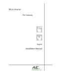
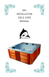
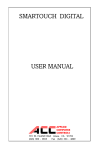
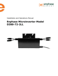
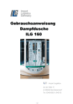
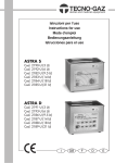
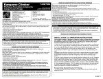
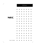
Micro-Inverter
INV250-45US RS485
INV250-45US PLC
INV250-45US
INV350-60US RS485
INV350-60US PLC
INV350-60US
English
Installation-Manual
IMPORTANT SAFETY INSTRUCTIONS
SAVE THESE INSTRUCTIONS
THIS MANUAL CONTAINS IMPORTANT
INSTRUCTIONS FOR MODELS:
INV250-45US, INV250-45US PLC AND INV250-45US RS485
INV350-60US, INV350-60US PLC AND INV350-60US RS485
THAT SHALL BE FOLLOWED DURING INSTALLATION
AND MAINTENANCE OF THE MICRO-INVERTER.
CONTACT INFORMATION
APtronic AG
An der Helle 26
59505 Bad Sassendorf-Lohne
Germany
http://www.aptronic-solar.com
[email protected]
OTHER INFORMATION
Product information is subject to change without notice.
All trademarks are recognized as the property of their respective owners.
Copyright © 2012 APtronic. All rights reserved.
Installation and Operation Manual for
INV250-45US RS485, INV250-45 PLC and INV250-45
INV350-60US RS485, INV350-60 PLC and INV350-60
Table of Contents
1.0 1.1 1.2 1.3 About this Manual
Important Safety Information
Scope
Target Audience
4
4
5
5
2.0 2.1 2.2 Storage and Transportation
Assembly, Installation, Operation and
Maintenance Label
5
3.0 3.1 3.2 3.3 Notes on Liability, Warranty and Service
Guaranty and Warranty Intended use and liability
Service
5
5
6
6
5
5
4.0 Product Description
4.1 Scope of Delivery
4.2 Dimensions
4.3 LED-Display
4.4 Protection Concepts
4.5 Derating
4.5.1 Derating as a function of input voltage
4.5.2 Derating as a function of ambient temp. /
wind speed
4.6 Connections Overview
4.6.1 Connections of PLC and NoCom Devices
4.6.2 Connections of RS485 Devices
6
7
7
7
7
7
7
5.0 5.1 5.2 5.3 5.4 8
8
9
9
9
Micro-Inverter Pre-Installation
Dimensioning of the PV-Generators
Compatibility and Capacity
Parts and Tools Required
Lighting Surge Protection
8
8
8
8
7.2 Registering with Utility Company
15
8.0 8.1 8.2 8.3 8.4 Troubleshooting
Troubleshooting an Inoperable Micro-Inverter
Other Faults
Disconnecting a Micro-Inverter from the
PV Module
Installing a Replacement Micro-Inverter
15
15
15
9.0 9.1 9.2 9.3 Further Information
Disposal
Care
Laws, Regulations and Technical Rules
16
16
16
16
Appendix
Technical Data for INV250
Technical Data for INV350
Derating Diagrams for INV250
Derating Diagrams for INV350
Certificate
Installation Map
Wiring Diagrams 208V
Wiring Diagrams 240V
16
16
18
19
20
21
22
23
24
25
6.0 Installation Procedure
10
6.1 Measure AC at the Electrical Utility Connection 10
6.2 Install the AC Branch Circuit Junction Box
10
6.3 Attach the Micro-Inverter to the PV Racking
10
6.4 Connect the Micro-Inverters (AC-Connection) 11
6.4.1 AC-Connection of PLC and NoCom Devices
11
6.4.2 AC-Connection of RS485 Devices
12
6.5 Ground the System
12
6.6 Communication Set-up
12
6.6.1 RS-485 Communication
12
6.6.2 Powerline Communication
13
6.6.3 Without Communication
13
6.7 Complete the Installation Map
13
6.8 Connect the PV Modules
14
6.9 Start Software
15
7.0 Commissioning, Operation and Registration
7.1 Commissioning
05.2012
15
15
INV250 / INV350
3
IMPORTANT SAFETY INSTRUCTIONS
SAVE THESE INSTRUCTIONS
THIS MANUAL CONTAINS IMPORTANT INSTRUCTIONS
FOR MODELS:
INV250-45US, INV250-45US PLC AND INV250-45US RS485
INV350-60US, INV350-60US PLC AND INV350-60US RS485
THAT SHALL BE FOLLOWED DURING INSTALLATION
AND MAINTENANCE OF THE MICRO-INVERTER.
1.0 About this Manual
This manual describes important information to follow
during the installation and service of the APtronic
Micro-Inverter. These instructions should always be
kept within reach of the inverter.
Since the documentation is updated frequently, please
visit the APtronic website (www.aptronic-solar.com/
downloads) for the latest information.
1.1 Important Safety Information
To ensure the safe installation and service of the
APtronic Micro-Inverter, this manual uses the following
types of safety symbols to indicate dangerous
conditions and important safety instructions that are to
be noted:
WARNING!
This indicates a situation where failure to follow
instructions may be a safety hazard or cause equipment
malfunction. Use extreme caution and follow
instructions carefully.
NOTE: This indicates information particularly important
for optimal system operation. Follow instructions
closely.
Symbols to be noted:
Direct Current Supply Symbol:
Alternating Current
Supply Symbol:
4
Ground Symbol:
Safety Instructions:
• Before installing the APtronic Micro-Inverter, please
read all instructions and cautionary markings in
the technical documentation, about the APtronic
Micro-Inverter System and the PV equipment.
• CAUTION: Perform all electrical installations in
accordance with all applicable local electrical codes
and the National Electrical Code (NEC), ANSI/NFPA
70.
• Be aware that only qualified personnel should
install or replace APtronic Micro-Inverters.
• Do not attempt to repair the APtronic MicroInverter; it contains no user-serviceable parts.
Tampering with or opening the APtronic MicroInverter will void the warranty.
• WARNING:
Be aware that the body of the APtronic MicroInverter can become very hot. The body can reach
temperatures over 70°C (158°F), when the ambient
temperature exceeds 25°C (77°F). To reduce risk
of burns, use caution when working with MicroInverters.
• Do NOT disconnect the PV module from the
APtronic Micro-Inverter without first removing AC
power.
• The installation instructions shall indicate that the
wiring methods used shall be in accordance with
the Canadian Electrical Code, Part I.
The micro inverter converts the power generated by
the PV modules from direct current into grid compliant
alternating current. For damages resulting from failure
to follow these instructions, we assume no liability.
When installing the inverter, please note the following
instructions for all assemblies and components of the
system.
In order to ensure faultless and safe operation of
this equipment, proper transport, expert storage,
installation, operation and maintenance is required.
During the operation of this equipment, certain
equipment parts carry hazardous voltages that can
INV250 / INV350
05.2012
cause serious injury or death. Always follow the
following instructions to minimize the risk of injury or
death.
•
1.2 Scope
This manual applies to the following micro-inverters:
• INV250-45US
• INV250-45US RS485
• INV250-45US PLC
• INV350-60US
• INV350-60US RS485
• INV350-60US PLC
1.3 Target Audience
•
•
•
•
This manual is for the installer of the types of inverters
listed in 1.2.
NOTE:
This guide assumes knowledge corresponding to a
recognized professional qualification as an electrician
and only qualified personnel should install or replace
APtronic Micro Inverters.
WARNING!
These servicing instructions are for use by qualified
personnel only. To reduce the risk of electric shock, do
not perform any servicing other than that specified in
the operating instructions unless you are qualified to
do so.
•
•
•
•
•
2.2 Label
2.0 Storage and Transportation
For storage and transport, the following warnings are to
be noted:
• All contacts should be kept dry and clean!
• Transport the inverter only in the given packaging.
2.1 Assembly, Installation, Operation and Maintenance
The following warnings must be observed:
• Before installing or using the APtronic MicroInverter, please read all instructions and note the
threats, warnings, and precautions.
• WARNING!
Proper grounding, wire sizing and appropriate
short-circuit protection must be provided to ensure
safe operation.
• Never remove the solar generator from the inverter,
while it is connected to the electricity network.
• Make sure that before carrying out inspections and
maintenance, the inverter is disconnected from the
mains supply and is secured against restarting.
05.2012
•
CAUTION:
Perform all electrical installations in accordance
with the safety regulations all applicable local
electrical codes and the National Electrical Code
(NEC), ANSI/NFPA 70.
Connect the APtronic Micro-Inverter to the
electricity network only after receiving prior
approval from the electrical utility company.
The electrical connection to the central building
shall be performed only by a licensed electrician.
If you mount the inverter at high altitude, avoid
possible falling risks.
Do not plug electrically conductive parts into the
plugs and sockets! Tools and working conditions
must be dry.
Do not under any circumstances interfere with or
manipulate the inverter or any other parts of the
system; it contains no user-serviceable parts.
Inappropriate alterations can cause damage!
Tampering with or opening the APtronic MicroInverter will void the warranty.
The installation shall be done in accordance to the
wiring methods and wire diameters in accordance
with the National Electrical Code (NEC), ANSI/NFPA
70. Connection schemes refer also page 24 and 25.
NOTE:
Do not connect the inverter to grids without an
earthed neutral conductor.
The installation instructions shall indicate that the
wiring methods used shall be in accordance with
the Canadian Electrical Code, Part I.
The label is located on the top side of the inverter.
The information on the label includes technical data,
type and serial number of the device as well as safety
instructions.
CAUTION:
Note that surfaces of equipment may be hot and create
a burn hazard.
3.0 Notes on Liability, Warranty and Service
Remarks on liability, warranty and service are listed
hereafter.
3.1 Guaranty and Warranty
APtronic grants an implied warranty of 2 years to the
inverter from date of purchase. Furthermore, APtronic
provides an additional limited warranty for 25 years.
For warranty questions, please contact your retailer
or installer. If your device has a defect or malfunction
during the warranty period, please also contact your
retailer or installer.
For further information on warranty, please see the
Warranty Disclaimer in Appendix XY.
INV250 / INV350
5
Warranty claims are excluded for:
• alterations or repairs to the unit
• opening of the inverter, for example by unscrewing
the cover
• improper use of device
• improper and non-standard installation
• improper operation
• operating the equipment with defective safety
devices
• impact of foreign objects and force majeure
(lightning, surge, storm, fire)
• inadequate or nonexistent ventilation of the device
• disregarding of safety regulations
• shipping damage
3.2 Intended use and liability
The APtronic Micro-Inverter converts the power
generated by the PV modules from direct current into
grid compliant alternating current and supplies it to the
power network.
Any other or additional use is considered improper.
The manufacturer / supplier shall not be liable for any
resulting damages. The risk is carried solely by the
operator.
Intended use also includes compliance with the
instructions and installation manual. Some of the
documents that you need for the registration and
inspection of your photovoltaic system are included
in the installation instructions. The inverter can be
operated with a permanent connection to the power
network. The inverter is not designed for mobile use.
Changes to the inverter are generally prohibited. For
any changes in the system a qualified electrician must
be called in.
3.3 Service
We have already set high standards in the development
phase on the quality and longevity of the inverter. In
spite of all quality assurance activities, disturbances
may occur in exceptional cases. In these cases, you will
get the maximum possible support to eliminate the
problem quickly and without bureaucratic complexities.
Please contact our service department directly.
APtronic Service Phone: +49 (0) 2927 - 9194 - 0
In order for the service department to respond quickly
and correctly, the following information is absolutely
necessary.
1) Details of the inverter:
Product description, type and serial number of the
inverter; this information can be found on the label on
the device.
Short description of the error:
• Did the fault occur immediately at the start or at a
later time?
6
•
•
Is the fault is reproducible or occurs only
sporadically?
What environmental conditions (radiation) were
present at the time of the error?
2) Information about the PV-generator
• What module manufacturer and type of module
was installed?
• What is the schematic of the PV-System?
4.0 Product Description
The APtronic Micro-Inverter is individually connected
to one or two PV-module, depending on technical
specifications. The Micro-Inverter converts the direct
current into grid compliant alternating current.
Through the individual conversion at each module,
the sun’s energy can ideally be used. In addition, the
micro-inverter solves another widespread problem in
conventional systems. Because of the series connection
in PV-systems using string- or central-inverters, the
PV-modules are codependent concerning performance.
If the performance of one PV-module drops, due to
shading or module mismatching for example, the
modules in the same string are affected negatively.
Through the individual connection in PV-systems using
micro-inverters the PV-modules work independently,
each at their maximum performance to increase energy
harvest.
The “plug-and play”-system eliminates connection
mistakes, making the installation safe and easy.
There are no high voltage DC circuits to handle and
installation time and costs are reduced.
Installations are effective ranging from small family
houses to large office fronts and can be installed on
any available space, regardless of orientation, shading
or module tolerances. Each system can be rearranged
or upgraded with more PV-modules when needed,
for example with performance expansion or building
modifications.
With the micro-inverter, it is possible to monitor the
performance of PV-systems on modular basis, which
enables comprehensive monitoring and fast problem
recognition. In that way, not only an increase in energy
earning can be provided, but also a decrease in energy
losses can be achieved by detecting and localizing
problems quickly and effectively.
The housing of the micro-inverter is NEMA 4 protected
and designed for operating temperatures from -25 °
C to 70 ° C. If the temperature inside the case exceeds
a certain value, the inverter will reduce the maximum
power to protect itself. Systems with micro-inverters
are easy to design and install. Each inverter can be
mounted to the mounting bracket below the PV
modules, however, recommended is a place where a
INV250 / INV350
05.2012
service can be performed easily.
An overview of the technical data of the inverter can be
found on pages 18 and 19.
Feeding Operation:
Depending on the power the blink frequency is
increasing. The following blink frequencies show
percentages as a function of the device power:
4.1 Scope of Delivery
0% to 3%
3% to 30%
30% to 60%
60% to 85%
85% to 100%
The package includes:
• Inverter
• End Caps (depending on version)
• Quick Start Guide and further information on CD
• AC connector and cap (depending on version)
LED 0.5 sec. „ON“ 2 sec. „OFF“
LED 0.5 sec „ON“ 1 sec. „OFF“
LED 0.5 sec „ON“ 0.5 sec „OFF“
LED 0.5 sec „ON“ 0.2 sec „OFF“
LED continuously „ON“
Non-feeding Operation:
When in non-feeding operation, the LED indicates
certain output stages, which are described hereafter.
These can be used to troubleshoot the inverter in case
of malfunction. Each stage indication starts with the
following sequence:
4.2 Dimensions
W
Sequence starts: 2 sec „ON“, 0.5 sec “OFF“
D
H
Model
Width
[mm]
Depth
[mm]
Height
[mm]
INV250-45US
INV350-60US
314
211
67
INV250-45US RS485
INV350-60US RS485
314
211
67
INV250-45US PLC
INV350-60US PLC
314
211
67
Output Stages:
Synchronization running:
LED 1sec „ON“ 0.5sec „OFF“, one pulse
AC Voltage not in tolerance range:
LED 1sec „ON“ 0.5sec „OFF“, two pulses
DC Voltage not in tolerance range:
LED 1sec „ON“ 0.5sec „OFF“, three pulses
AC and DC Voltage not in tolerance range:
LED 1sec „ON“ 0.5 sec „OFF“, four pulses
Internal over-temperature:
LED 1sec „ON“ 0.5 sec „OFF“, five pulses
4.4 Protection Concepts
The following monitoring concepts and protection
plans are included in the APtronic scope of devices:
• Surge / varistors to protect the power
semiconductor
• temperature monitoring
• EMC filters to protect the inverter against highfrequency power disturbances
• varistors to earth on the mains side to protect the
inverter against surge voltages
4.3 LED-Display
4.5 Derating
During normal operation, the PV generators produce a
voltage when sufficient daylight or sunlight is present.
If this voltage at a certain level and corresponding time
period is applied to the inverter, the inverter starts to
feed into the grid. The inverter is equipped with an LED,
which gives information on the operating status and
causes for non-operation.
05.2012
Derating is the operation of a machine at less than its
rated maximum power in order to prolong its life or
safety reasons, which is described for the micro-inverter
hereafter.
4.5.1 Derating as a function of input voltage
Due to the maximum value of the input current from
the PV module of 11A, a maximum power results which
can be transformed by the inverter depending on the
input voltage. The limit of 11A is limited by the inverter
and cannot be exceeded. Similarly, the maximum load
INV250 / INV350
7
of the PV module is limited to 250W/350W (depending
on Inverter version). This results in the following
gradient of the maximum absorbed power as a function
of the input voltage from the PV module.
4.6.2 Connections of RS485 Devices
(see Graph Derating diagram P pv / I pv on pages 20/21)
4.5.2 Derating as a function of ambient temp. / wind speed
Different environmental conditions result depending
on the installation of the inverter. The ambient
temperature and air flow around the inverter affect
the inverter‘s performance capabilities. In the
inverter, a power control as a function of temperature
is integrated. The following charts represent the
maximum input power of the inverter over the ambient
temperature and wind speed.
DC connector PV-
(see Graphs:
- Derating diagram Ppv / T ambient 0m/s Wind Speed
- Derating diagram Ppv / T ambient 0,1 m/s Wind Speed
on pages 20/21)
DC connector PV+
RS 485 interface 1
RS 485 interface 2
Please note that the performance capabilities of
your PV module decreases with increasing module
temperature, in general with about 0.4%/°C. That
means, a module with 200W under STC conditions of
70°C and 1000 W/m² provide only a maximum of 164W.
4.6 Connections Overview
The connections of the Micro Inverter are described
hereafter.
4.6.1 Connections of PLC and NoCom Devices
AC connector 1
AC connector 2
climatic membrane
5.0 Micro-Inverter Pre-Installation
The following instructions describe the aspects to be
noted before the installation of the Micro-Inverter.
In addition, please note the important safety
information listed in 1.1.
5.1 Dimensioning of the PV-Generators
The selection of the PV generator is of central
importance to the design of a PV system. It is highly
relevant that the PV module fits to the inverter.
DC connector PVDC connector PV+
climatic membrane
AC connector
8
The number of PV modules connected in series must be
chosen so that the output voltage of the PV generator,
even in extreme outdoor temperatures does not exceed
the allowed input voltage range of the inverter. In North
America, module temperatures between -15°C to +70°C
should be assumed. Depending on the installation
of the generators and the geographical location,
temperatures of +60°C or +70°C are used in the stress
voltage calculation. Please note the temperature
coefficient of PV modules. The following criteria must
be met for the voltage of the PV generator:
INV250 / INV350
05.2012
Uo (-15 ° C) <max. Input voltage:
45 V and -15°C for INV250
60 V and -15°C for INV350
5.2 Compatibility and Capacity
The open circuit voltage of the connected PV generator
must be in the allowed input voltage range, even at
very low outdoor temperatures (-10°C). With a lowering
of the temperature of 25°C to -10°C, the open circuit
voltage at 12 V modules increases by approx. 2.8 V
per module (approx. 5.6 V at a 24 V module). The open
circuit voltage of the PV generator must be less than
45V for INV250 and less than 60 V for INV350.
UMPP (+60°C)> min. Input voltage:
18 VDC for INV250
20 VDC for INV350
For the INV250-45US /-RS485 /-PLC this voltage is 18 V.
For the INV350-60US /-RS485 /-PLC this voltage is 20 V.
The UMPP-voltage of the connected circuit branch
should not fall below the allowable input voltage range,
even at very high module temperatures (+60°C). With
a temperature rise of 25°C to 60°C, the UMPP-voltage
decreases for 12 V modules to approximately 3.6 V per
module (7.2 V at a 24 V module).
The UMPP-voltage of the PV generator should be at
least 18V (for INV250) or 20V (for INV350).
If the UMPP-voltage falls below the allowed input
range, the system still works without problems. In this
state, it is not feeding the maximum possible power
into the grid, but slightly less. It does not affect the
inverter when a connected PV generator supplies
a higher than the maximum usable input power,
provided that the input voltage is within the acceptable
range.
It may happen that the inverter switches off for safety
reasons, if the PV generator provides more than the
max. DC input power of the inverter for a short time,
especially with changing cloud coverage and relatively
low-temperature conditions. Normally, the control of
the inverter is so dynamic that it continues to operate
without interruption.
Generally, in Central Europe a south orientation with
30° inclination should be chosen for optimum energy
yield of the PV array. The optimum power factor
for south-facing systems is 1.10 to 1.25. In an eastwest system the power factor can be chosen to 1.30.
Requirement is that all other values of the inverter are
met. For exposed locations in the mountains or in the
southern regions, a corresponding reduction (<1.15)
of the power ratio is required. For questions please
contact our customer service.
05.2012
The Micro-Inverters listed in Section 1.2 are compatible
with a wide variety of modules, starting with 48-cells up
to 96 cells modules, as long as it is provided that under
all occurring environmental influences, the following
DC Input voltages are NOT exceeded:
45V for INV250
60V for INV350
For more information, see Technical Data on pages 18
and 19 in this manual.
Refer to the APtronic website (http://www.aptronicsolar.com/downloads) for a list of electricallycompatible PV modules.
Utility service requirements: 240V version works only
with split phase 240V service. The 208V version works
only with three phase 208V service, or 208 single phase
service.
5.3 Parts and Tools Required
You may need to provide other parts and tools that
could be required for installing a PV-System using
Micro-Inverters. These may include, but are not limited
to the following:
• Continuous grounding conductor, grounding
washers
• Number 2 Phillips screwdriver
• Sockets, wrenches for mounting hardware
• Torque wrench
• Mounting hardware suitable for module racking
5.4 Lighting Surge Protection
Lightning does not actually need to strike the
equipment or building where PV system is installed
to cause damage. Often, a strike nearby will induce
voltage spikes in the electrical grid that can damage
equipment. APtronic Micro-Inverters have integral
surge protection. However, if the surge has sufficient
energy, the protection built into the Microinverter can
be exceeded, and the equipment can be damaged.
Since the APtronic Limited Warranty does not cover
“acts of God” such as lightning strikes, and since
lightning strikes can occur anywhere, it is best
practice to install surge protection as part of any solar
installation.
INV250 / INV350
9
6.0 Installation Procedure
Please note the important safety information listed in
1.1 as well as the Assembly, Installation, Operation and
Maintenance Warnings listed in 2.1.
In the following section, an overview is given on how
the micro-inverter is to be installed.
Step 1 Measure AC at the Electrical Utility
Connection
Step 2 Install the AC Branch Circuit Junction Box
Step 3 Attach the Micro-Inverter to the PV Racking
Step 4 Connect the Micro-Inverters (AC-Connection)
Step 5 Ground the System
Step 6 Communication Set-up
Step 7 Complete the Installation Map
Step 8 Connect the PV Modules
Step 9 Start Software
6.1 Measure AC at the Electrical Utility Connection
To ensure proper system operation, measure AC line
voltage at the electrical utility connection to confirm
that it is within range. Acceptable ranges are shown
below.
Three-phase 208 VAC
183 to 229 VAC L1 to L2 to L3
106 to 132 VAC L1,L2, L3 to neutral
Single-Phase 240 VAC
211 to 263 VAC L1 to L2
106 to 132 VAC L1, L2 to neutral
NOTE:
Check the labeling on the AC Cabling to be sure that
the cable matches the electrical utility service at the
site. Use 208 VAC (208 VAC three-phase) Cabling at
sites with three-phase 208 VAC service, or use 240 VAC
Cabling at sites with 240 VAC single-phase service. Use
240 VAC cable at sites with 208 single-phase service.
Please refer to page 24 (208V) and 25 (240V) for wiring
diagrams.
NOTE: The operation at grids with neutrals which
are not grounded is not allowed!
6.2 Install the AC Branch Circuit Junction Box
DANGER:
Risk of Electrical Shock. Be aware that installation of this
equipment includes risk of electric shock. Do not install
the AC junction box without first removing AC power
from the PV-System.
WARNING:
Only use electrical system components approved for
wet locations.
10
WARNING:
Do NOT exceed the maximum number of microinverters in an AC branch circuit as listed in 6.4.1
and 6.4.2 of this manual. You must protect each
micro-inverter AC branch circuit with a two pole 20A
maximum breaker.
WARNING:
Open all ungounded conductors of the cicuit to which
it is connected.
The installation of a circuit junction box does not
necessarily need to be installed for a PV-system with
micro-inverters to work. If however, circuit junction
boxes are installed, be sure to follow all common
installation security measures and install in accordance
with all applicable local electrical codes and the
National Electrical Code (NEC), ANSI/NFPA 70.
The installation instructions shall indicate that the
wiring methods used shall be in accordance with the
Canadian Electrical Code, Part I.
6.3 Attach the Micro-Inverter to the PV Racking
To find the optimal location for the inverter, a summary
of key criteria that should be considered is listed below.
Select an installation location so that the following
points will find consideration:
• Ensure best possible access to the unit for
installation and any subsequent service.
• Ensure a minimum distance of 20 mm between the
roof top and the bottom of the inverter.
• In addition, we recommend a distance of 25 mm
between the back of the PV module and the top of
the inverter.
• The device is designed for attachment to the
mounting bracket under a PV module, but other
mounting options are possible.
• The free flow of air around the case must not be
hindered.
NOTE!
Because of the voltage of the PV generator, there is
a greater current flow on the DC side than on the AC
side. Due to this, there are higher losses on the DC side
with the same cable cross-sections and lengths. For this
reason, the placement of the inverter in the vicinity of
the PV module is useful. The line lengths on the DC side
should be kept as correspondingly short.
To Install the Micro-Inverter under the PV module,
please use suitable accessories corresponding to the
framework used, for example with the use of screws
and sliding blocks.
In order to mount the inverters on the PV-framework
below the PV-modules, note the following:
Select the approximate center of the PV module on the
mounting profile. Fasten the inverter centered on this
mark with the help of accessories that are compliant
with the APtronic Micro-Inverter and the framework
INV250 / INV350
05.2012
used. This could be done by fastening the inverter with
screws and sliding blocks below the inverter supports
at the framework profiles.
Mounting slots on the Micro-Inverter are 0.33 inches in
diameter. Maximum bolt size is 5/16 inch.
The two slots on the Micro-Inverter are 4 inches apart.
If the PV system consists of more than one inverter, the
individual inverters are connected via connecting lines:
If using grounding washers (e.g., WEEB) to ground the
Micro-Inverter chassis to the PV module racking, choose
a grounding washer that is approved for the racking
manufacturer. Install a minimum of one grounding
washer per Micro-Inverter.
Please note the manufacturer’s installation instructions
for the grounding washers.
6.4 Connect the Micro-Inverters (AC-Connection)
NOTE:
When connections are made, standards and
regulations, as well as the safety information contained
in this manual must be followed.
NOTE:
Do not connect the inverter to grids without an earthed
neutral conductor.
Please note the important safety information listed in
1.1 as well as the Assembly, Installation, Operation and
Maintenance Warnings listed in 2.1.
Follow local regulations for work on electrical
installations.
PIN L
L1 (red)
PIN N
L2 (black)
PE (green)
Make sure that you use sufficiently large cable crosssections to avoid major resistance between the
domestic distribution and the respective inverter.
Choose a cable quality which is sufficient for the use in
your application.
The connector can accommodate a maximum cross
section of AWG 15 with a flexible cable with cable core
end. In a rigid core cable, a connector with AWG 13 is
possible. Note the resulting maximum line length.
6.4.1 AC-Connection of PLC and NoCom Devices
The layout of the AC connection depends on the
version of the Micro Inverter. For both versions the
following applies:
Connect the inverters using the AC wiring from one
inverter to the next, in ways that are further explained
for each version in the following sections. However, for
both versions, it is important that the AC connections
are made only up until the maximum permitted
number of inverters in an AC power circuit is reached.
DO NOT exceed the maximum allowable number of
inverters in an AC power circuit, as noted in chapter
6.4.1 and 6.4.2.
Open AC connections at the end of an AC power circuit
must be sealed with a protective cap.
To achieve the degree of protection NEMA 4, all unused
PV input jacks and plugs must be sealed with caps.
At a relatively high resistance, i.e. with long line length
on the AC side, the feeding voltage increases at the
supply terminals of the inverter.
This voltage is measured by the inverter. If the voltage
at the supply terminals exceeds the grid over voltage
limit, the inverter shuts off due to grid over voltage. It is
essential to take this fact into account for the AC wiring
and dimensioning of the AC line.
05.2012
For the Powerline Communication Version and the
Version without communication features:
The inverter is equipped with one AC terminal on
the right side of the connection area, a 20A 3-pin AC
connector. The supply is phase to phase 208V or 240V
depending on version. The inverters are connected
using 20A 3-pin AC extension cables and distribution
blocks, with one input and three outputs, to form a
continuous AC power circuit. On one strand (power
circuit), which is equipped with a 20A two pole circuit
breaker, up to 12 inverters can be operated. This circuit
breaker acts also as a pole switch to disconnect the
Inverter from the mains.
The distribution blocks are not included in scope of
delivery of the Micro Inverter, see accessories overview
for ordering details.
INV250 / INV350
11
Open AC connections at the end of an AC power circuit
must be sealed with a protective cap. This cap must be
ordered, see accessories overview.
If you are not using grounding washers to ground the
micro-inverter chassis as described in step XY, follow
the step below.
Each APtronic Micro-Inverter comes with a grounding
fixture that can accommodate a 6-8 AWG conductor.
Route a continuous grounding electrode conductor
through each of the micro-inverters to the NEC
approved AC grounding electrode. The racking and
module could be grounded to this conductor using a
crimp connection.
6.4.2 AC-Connection of RS485 Devices
INV350-60US RS485
An alternative method would be to connect the microinverter to the grounded racking using a grounding
washer approved for the racking.
6.6 Communication Set-up
For the RS-485 Communication Version:
The inverter is equipped with two AC terminals on
the right side of the connection area. The inverter has
two 3-pin AC connectors. The supply is single phase.
Connect the last Micro Inverter to the next one using
AC connector cabling and continue with following
inverters. The AC connectors are polarized differently,
so that multiple inverters can be connected to form
a continuous AC power circuit. On one strand (power
circuit), which is equipped with a 20A two pole circuit
breaker, up to 12 inverters can be operated. This circuit
breaker acts also as a pole switch to disconnect the
Inverter from the mains.
Open AC connections at the end of an AC power
circuit must be sealed with a protective cap. This cap is
included.
6.5 Ground the System
Each APtronic Micro-Inverter comes with a grounding
fixture that can accommodate a 6-8 AWG conductor.
Route a continuous grounding electrode conductor
through each of the micro-inverters to the NECapproved AC grounding electrode.
12
The following sections describe how to set-up
communication (monitoring), depending on Version of
the Micro-Inverter.
6.6.1 RS-485 Communication
If your Micro-Inverter is not equipped with TIA485
(RS485) Interface, then this step can be skipped.
For the RS-485 Version, the following has to be noted:
To allow for remote monitoring of your PV system, the
inverters have two additional RS485 ports. The RS485
interface is used for remote communication. The RS485
communications can be established over a distance
of up to 1000 meters. In the case of an external power
limiting, the signal transmission is also performed via
the RS 485 interface.
Using this interface, several (max.32) inverters can be
monitored simultaneously. For this, each inverter has
its own address. The address setting is performed in
the service level. The system data is taken from the data
logger. Please refer to accessories overview for suitable
datalogger. For more information on these products,
see the respective manuals.
Using pre-assembled interface lines, the
communication between the inverters and the data
logger can be set up quickly and easily. For longer
distances between the inverters or the data logger,
please use free-attachable cable or a suitable data
cable; please refer to accessories overview for ordering
details.
INV250 / INV350
05.2012
(max.32) inverters can be monitored simultaneously,
over a maximum distance of about 100 meters. For this,
each inverter has its own address. The address setting is
performed in the service level.
The RS485 is a two wire (A, B) linear bus system. I.e.
the device has to be wired in a line. It is necessary to
put terminators on both ends. Adequate termination
resistors for the Micro-Inverters are available; please
refer to accessories overview for ordering details.
Additional the Bus master, generally a data logger,
has to provide a bias-network. When selecting a data
logger, please note the possibly necessary features of
the statutory requirements or technical directives from
Chapter 4. To choose the right data logger, you should
contact your retailer.
For the inverter, the external power limitation is
realized on the RS485 interface. For the construction of
communication, we recommend a twisted and shielded
data cable of the type Cat 5 / T568B.
The following figure shows the configuration of the
connector:
For communication only Pair 3 is needed.
So wire A of the RS485-Bus is connected to Pin 6 and
wire B to Pin 3. Additional Pin 8 and the cable shield are
connected to Earth to protect against electromagnetic
influences. These wires as well as the shield must not
be connected at the bus master. It is recommended to
connect unused wires to the bus master GND.
To build up a low cost monitoring, APtronic provides
the AP-Solar datalogger-software for free. Additional, to
connect the RS485-Bussystem to a standard home PC,
APtronic recommends the USB-Nano485/OP form cti
(APtronic Part Number for ordering: 51-05-500009-1),
which sets up the RS485-signals to standard USB and
provides selectable termination resistor, bias network
and GND connection.
6.6.2 Powerline Communication
If the Microinverter is equipped with a PowerlineCommunication-Interface this chapter describes how
to wire and monitor the system. With the PowerlineCommunication the data exchange takes place on the
AC-Lines. Therefore there’s no need for additional data
lines to the Microinverter. Using this interface, several
05.2012
In combination with the APtronic PLC-Gateway, it’s
possible to build up a simple monitoring Network. The
following diagram shows how to connect the MicroInverters to the Gateway:
The APtronic Gateway is needed to convert the
Powerline-Signals into standard RS-485. For more
information on the APtronic PLC-Gateway the please
refer to separate Product Manual. To build up a simple
low cost monitoring with a standard home PC please
refer to 6.6.1.
6.6.3 Without Communication
The Micro-Inverter versions without communications
are not intended for comprehensive monitoring, and
therefore cannot be monitored using the APtronic
Datalogger, Gateway or Software. For the user to
monitor the basic PV-system data, the user can install
an independent energy-monitoring-device.
6.7 Complete the Installation Map
The installation Map an aid to visualize the physical
location of each Micro-Inverter in your PV installation.
This will also simplify the setup of the virtual array using
the Software AP-Solar, which is included in the scope of
delivery.
Use the blank map on page 23 to record the locations
of each Micro-Inverter or create your own map as a topdown view of the array. Write down the last 5 digits of
the Serial number at the respective Inverter location on
the map. With the software, the last 5 digits can be used
to identify the Micro-Inverters and rename them (e.g.
Inverter 1,2,3, …) for simplified identification.
INV250 / INV350
13
6.8 Connect the PV Modules
NOTE: Completely install all Micro-Inverters and all
AC connections prior to installing the PV modules.
To ensure maximum security against dangerous touch
voltages, it is necessary to make sure that the DC
connection cables coming from the PV generator are
not in contact with the ground potential during the
installation of a photovoltaic system.
CAUTION:
- Risk of damage! Make sure the correct polarity at the
terminals!
- Check the PV generator for ground fault before you
connect it to the inverter.
Before you connect the DC cables to the inverter, check
if the maximum PV-module voltage is suitable for
feeding into the inverter. The presence of a PV module
voltage that is too high leads to the destruction of the
device. Pay attention to the increase of the open circuit
voltage of the solar field at low temperatures!
Prior to the installation of PV modules, the inverter
should be fully installed and the AC connections
between the inverters should be performed. Install, if
possible, the PV modules above the respective inverter
to the PV-racking. The connection cables of the PV
modules are connected to the inverter on negative and
positive polarized MC4 plug and socket.
The positively and negatively polarized MC4-connector
of a single PV module can be connected to the opposite
pole connectors of a single inverter. First, the positive
DC cable from the PV module is connected to the
negative DC connector socket of the inverter. Then the
negative DC cable of the PV module is connected to the
positive DC connector socket of the inverter.
When disconnecting the cable couplings press the
mounting link together by hand and disconnect the
cable coupling.
The DC wiring of an inverter with a PV module looks
conceptually like this:
This step is performed for all remaining PV modules,
each to the corresponding inverter without exceeding
the maximum number of inverters in a power circuit.
The exact use of the DC connectors is as follows:
Push together the cable coupler until it clicks. Correct
latching control by carefully pulling on the cable
connectors. When the compounds are fully engaged,
check that there are no sharp bends or kinks.
14
INV250 / INV350
Inverter
Module Connection Cable
PV-Generator (modules)
05.2012
6.9 Start Software
•
When the system is energized and the AP Datalogger or
Gateway detects all the installed Micro-Inverter, please
install the software on your personal computer to
ensure proper operation of the system.
For direction on how to use the software, please refer to
the Software User Manual.
7.0 Commissioning, Operation and Registration
The following Section describes the procedures for
Commissioning, Operating, and Registering the System.
description of the inverter or rather declaration and
clearance certificate information about the shortcircuit rating of switching devices
8.0 Troubleshooting
Adhere to all the safety measures described throughout
this manual. Qualified personnel can use the following
troubleshooting steps if the PV system does not
operate correctly.
WARNING: Do not attempt to repair the APtronic MicroInverter; it contains no user-serviceable parts. If it fails,
please contact APtonics’ Service Department to assist.
WARNING:
Ensure that all AC and DC wiring is correct. Ensure that
none of the AC and DC wires are pinched or damaged.
Ensure that all AC junction boxes are properly closed.
For further troubleshooting, see LED-Indicators in
chapter 4.3.
7.1 Commissioning
To troubleshoot an inoperable Micro-Inverter, follow
the steps in the order shown:
1. Turn ON the AC-disconnect or circuit breaker on
each Micro-Inverter AC branch circuit.
2. Turn ON the main utility-grid AC circuit breaker.
Your system will start producing power after a fiveminute wait time.
When commissioning for the first time or when the
inverter was not supplied with a PV power for a
longer time, the inverter can require some connection
attempts over a period of 5 minutes to go in feeding
operation.
7.2 Registering with Utility Company
For registration and the acceptance process of a PV
system, please inform yourself concerning the details of
each utility.
Commissioning usually runs as follows:
• Submission of documents to the relevant local
Utility Company
• installation of the system
• installation of the meter by the Utility Company
For this purpose, the following documents are generally
required:
• application / completion notification by registered
installer
• site plan, setting out the property boundaries and
the site of the PV system
• overview diagram of the entire system with the
used equipment (pole diagram)
• datasheet for generating systems (utility
announcement)
• description of the protective device with
information about the type, circuit, make and
function
05.2012
8.1 Troubleshooting an Inoperable Micro-Inverter
1. Verify the connection to the utility grid. Make sure
2.
3.
4.
5.
6.
7.
that the utility frequency and voltage are within
allowable ranges listed in the Technical Data section
on pages 18 and 19 of this manual.
Make sure that the utility power is present at the
inverter in question by first removing AC and
then DC power. Do NOT under any circumstances
disconnect the DC wires while the Micro-Inverter is
producing power.
Check the AC distribution blocks between all
the Micro-Inverters. Check that each inverter is
energized by the electricity network as described in
the previous step.
Any AC disconnects need to be checked if they are
operating correctly and closed.
Check to see if the PV module DC voltage is within
the allowable range shown in the Technical Data
section on pages 18 and 19 of this manual.
Verify that the DC connections between the MicroInverter and the PV module are connected properly.
If the problem persists, please call customer
support at APtronic.
8.2 Other Faults
Other faults are reported to the AP-Solar Software.
Refer to the AP-Solar Installation and Operation Manual
for troubleshooting procedures.
WARNING:
Be aware that only qualified personnel should
troubleshoot the PV array or the APtronic MicroInverter.
INV250 / INV350
15
WARNING:
Never disconnect the DC wire connectors under load.
Ensure that no current is flowing in the DC wires prior
to disconnecting. An opaque covering may be used to
cover the module prior to disconnecting the module.
WARNING:
Always disconnect AC power before disconnecting the
PV module wires from the APtronic Micro-Inverter. The
AC connector of the first Micro-Inverter in a branch
circuit is suitable as a disconnecting means once the
AC branch circuit breaker in the load center has been
opened.
WARNING:
Open all ungrounded conductors of the circuit to which
it is connected.
8.3 Disconnecting a Micro-Inverter from the PV Module
Please note the important safety information listed in
1.1 as well as the Assembly, Installation, Operation and
Maintenance Warnings listed in 2.1.
Follow local regulations for work on electrical
installations.
WARNING:
- Risk of death by electric shock on live connections!
Even after disconnecting the electrical connections,
there are still perilous voltages present in the inverter.
- Wait five minutes or so until you do further work on
the inverter.
For adjustment, maintenance and repair work, you
need to turn off the inverter.
• Switch off the grid by activating the circuit breaker
(disable external locking mechanisms).
• Check for zero-potential after the shutdown.
To ensure the Micro-Inverter is not disconnected from
the PV modules under load, adhere to the following
disconnection steps in the order shown:
1. Disconnect the AC by opening the branch circuit
breaker.
2. Disconnect the first AC connector in the branch
circuit.
3. Cover the module with an opaque cover.
4. Using a DC current probe, verify there is no current
flowing in the DC wires between the PV module
and the Micro-Inverter. Care should be taken when
measuring DC currents, most clamp-on meters
must be zeroed first and tend to drift with time.
5. Disconnect the PV module DC wire connectors from
the Micro-Inverter.
6. Remove the Micro-Inverter from the PV array
racking.
16
8.4 Installing a Replacement Micro-Inverter
Attach the replacement micro-inverter to the PV
module racking using hardware recommended by your
module racking vendor. If you are using grounding
washers to ground the chassis of the micro-inverter,
the old grounding washer should be discarded, and a
new grounding washer must be used when installing
the replacement micro-inverter. For torque values
please refer the recommendations for installation of the
washer vendor.
1. If you are using a grounding electrode conductor
to ground the micro-inverter chassis, attach the
grounding electrode conductor to the microinverter ground clamp.
2. Connect the AC cable of the replacement microinverter and the neighboring micro-inverters to
complete the branch circuit connections.
3. Energize the branch circuit breaker and verify that
the replacement inverter is working properly by
checking the indicator light.
4. Initiate a device scan with the AP-Solar Software.
9.0 Further Information
The following sections provide further guidance to the
inverter.
9.1 Disposal
Dispose of the packaging in accordance with
generally applicable laws and regulations. Keep the
environmental requirements for recovery, reuse and
disposal of materials and components.
9.2 Care
The surface of the inverter should generally be kept free
of dust and dirt.
9.3 Laws, Regulations and Technical Rules
In preparing the current solar technology systems for
the respective country laws and regulations are to be
noted for country, federal, European, and international
levels.
The generally accepted engineering standards
considered to apply, which are usually formulated in
the form of standards, guidelines, rules, regulations
and technical rules of state and federal agencies,
utility companies, and professional associations and
committees for the relevant department.
Through the installation of solar panels / solar system,
the requirements for roofing, waterproofing and
exterior wall cladding according to the rules of the
INV250 / INV350
05.2012
German Roofing Trade, or equivalent national and
international guidelines and standards are to be
considered.
An examination of stability, the thermal protection
and the aging behavior is required for retrospective
installation.
To comply with the regulations on accident prevention,
the use of safety systems (safety belt, scaffolding,
arresting gear, etc.) may be required. These security
systems are not included and must be ordered
separately.
The installation must be performed by professionally
qualified and authorized personnel with an approved
training certificate (by a state or national organization)
for the respective department.
Inside the inverter, there are NO serviceable or
exchangeable parts. The inverter may neither be
opened by the customer nor the system installer.
FCC Compliance
This equipment has been tested thru FCC part 15 Class
B. The unit complies with the defined standard.
During the unit is under influence of strong electric
fields the unit may be disturbed. This may cause
random reduction of output power or a short time shut
down of the unit. After the electric field is removed, the
unit will return to normal operation.
05.2012
INV250 / INV350
17
Technical Data for INV250
INV250-45
Micro-Inverter
Description
The APtronic Micro-Inverter INV250-45 converts the
generated energy into grid-compliant alternating
current. For this, the INV250-45 is directly connected
to a module. The Individual conversion allows optimal
utilization of solar energy.
The micro-inverter INV250-45 operates up to a
maximum power of 250W with a PV input voltage of
45V.
In systems with central or string inverters, the series
connection of the PV modules often causes energy
losses. If the output from a module drops, for example
through shading, it reduces the performance of the
whole string. This problem is solved by micro-inverters,
because in systems with these inverters, the modules
work independently and guarantee the highest
possible.
50 Hz-Version
· Nominal AC voltage: 230V
· Nominal AC voltage range: 184V ... 264V
· Frequency: 50.0 Hz
· Frequency range: 47.5 Hz ... 51.5 Hz
· Productsafety:
IEC 62103:2003, IEC 62109-1:2010,
IEC 55011B, EN 50178:1997
· EMC: EN 61000-6-2, EN 61000-6-3
60 Hz-Version
· Nominal AC voltage: 208 V oder 240 V
· Nominal AC voltage range: 184V ... 264V
· Frequency: 60.0 Hz
· Frequency range: 59.5 Hz ... 60.3 Hz
· Productsafety:
UL 1741:2010, IEEE 1547:2003,
CSA C22.2
· EMC: FCC Part 15 Class B
Input
· Maximum PV power: 250 W
· Maximum DC voltage: 45 V
· Min./Max. start voltage: 18 V / 45 V
· MPP range: 20 ... 40 V
· Maximum DC current: 11 A
Output
· Maximum AC Power: 240W
· Nominal Current: 1.0A
· Power factor: > 0.99
Efficiency
· Peak inverter efficiency: 93.5%
· European efficiency: 92.6%
· Nominal MPP efficiency: 99.8%
Features
· Communication Versions: Powerline / RS485 / No Com
· MSD integrated
· Safety class : Class I
Mechanical Data
· Operating Temperature: -25°C ... +70°C
· Night time power consumption: 30mW
· Max. altitude a.s.l.: 2000m
Housing
· 314mm x 267mm x 66.5mm (BxHxT)
· Weight: 2.5kg
· Cooling: Natural convection
· Protection Degree: NEMA 4
· Enclosure mterial: Aluminum
Your partner or customized Power Supplies
18
INV250 / INV350
APtronic AG
An der Helle 26
D-59505 Bad Sassendorf - Lohne, Germany
Tel. +49 (0) 2927-9194-777
Fax +49 (0) 2927-9194-778
Email: [email protected]
05.2012
Technical Data for INV350
INV350-60
Micro-Inverter
Description
The APtronic Micro-Inverter INV350-60 converts the
generated energy into grid-compliant alternating
current. For this, the INV350-60 is directly connected
to a module. The Individual conversion allows optimal
utilization of solar energy.
The micro-inverter INV350-60 operates up to a
maximum power of 350W with a PV input voltage of
60V.
In systems with central or string inverters, the series
connection of the PV modules often causes energy
losses. If the output from a module drops, for example
through shading, it reduces the performance of the
whole string. This problem is solved by micro-inverters,
because in systems with these inverters, the modules
work independently and guarantee the highest
possible return.
50 Hz-Version
· Nominal AC voltage: 230V
· Nominal AC voltage range: 184V ... 264V
· Frequency: 50.0 Hz
· Frequency range: 47.5 Hz ... 51.5 Hz
· Productsafety:
IEC 62103:2003, IEC 62109-1:2010,
IEC 55011B, EN 50178:1997
· EMC: EN 61000-6-2, EN 61000-6-3
60 Hz-Version
· Nominal AC voltage: 208 V oder 240 V
· Nominal AC voltage range: 184V ... 264V
· Frequency: 60.0 Hz
· Frequency range: 59.5 Hz ... 60.3 Hz
· Productsafety:
UL 1741:2010, IEEE 1547:2003,
CSA C22.2
· EMC: FCC Part 15 Class B
Input
· Maximum PV power: 350 W
· Maximum DC voltage: 60 V
· Min./Max. start voltage: 18 V / 60 V
· MPP range: 20 ... 50 V
· Maximum DC current: 11 A
Output
· Maximum AC Power: 330W
· Nominal Current: 1.4A
· Power factor: > 0.99
Efficiency
· Peak inverter efficiency: 93.5%
· European efficiency: 92.3%
· Nominal MPP efficiency: 99.8%
Features
· Communication Versions: Powerline / RS485 / No Com
· MSD integrated
· Safety class : Class I
Mechanical Data
· Operating Temperature: -25°C ... +70°C
· Night time power consumption: 30mW
· Max. altitude a.s.l.: 2000m
Housing
· 314mm x 267mm x 66.5mm (BxHxT)
· Weight: 2.5kg
· Cooling: Natural convection
· Protection Degree: NEMA 4
· Enclosure mterial: Aluminum
Your partner or customized Power Supplies
05.2012
INV250 / INV350
APtronic AG
An der Helle 26
D-59505 Bad Sassendorf - Lohne, Germany
Tel. +49 (0) 2927-9194-777
Fax +49 (0) 2927-9194-778
Email: [email protected]
19
Derating Diagrams for INV250
Derating diagram
P pv / I pv
Derating diagram
Ppv / T ambient 0m/s
Wind Speed
Derating diagram
Ppv / T ambient 0.1 m/s
Wind Speed
20
INV250 / INV350
05.2012
Derating Diagrams for INV350
Derating diagram
P pv / I pv
Derating diagram
Ppv / T ambient 0m/s
Wind Speed
Derating diagram
Ppv / T ambient 0.1 m/s
Wind Speed
05.2012
INV250 / INV350
21
Certificate
22
INV250 / INV350
05.2012
05.2012
INV250 / INV350
N
M
L
K
J
I
H
G
F
E
D
C
B
A
(circle one)
NSEW
1
Panel Group
Tilt
Sheet__ of __
2
3
4
5
Installer Information
to Sheet: ___
to Sheet: ___
Installation Map
6
7
Customer Information
Installation Map
to Sheet: ___
23
to Sheet: ___
Wiring Diagrams 208V
NOTE:
The operation at grids with neutrals which
are not grounded is not allowed!
NOT APPROVED
24
INV250 / INV350
05.2012
Wiring Diagrams 240V
NOTE:
The operation at grids with neutrals
which are not grounded is not allowed!
NOT APPROVED
05.2012
INV250 / INV350
25
APtronic AG • An der Helle 26 • 59505 Bad Sassendorf - Lohne • Germany
Phone +49 (0) 2927 9194-0 • Fax +49 (0) 2927 9194-50 • www.aptronic-solar.com
26
INV250 / INV350
05.2012