1
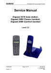
DIGITAL BETACAM/HDCAM PROCESSOR BOARD
HKSR-5802
! WARNING
This manual is intended for qualified service personnel only.
To reduce the risk of electric shock, fire or injury, do not perform any servicing other than that
contained in the operating instructions unless you are qualified to do so. Refer all servicing to
qualified service personnel.
! WARNUNG
Die Anleitung ist nur für qualifiziertes Fachpersonal bestimmt.
Alle Wartungsarbeiten dürfen nur von qualifiziertem Fachpersonal ausgeführt werden. Um die
Gefahr eines elektrischen Schlages, Feuergefahr und Verletzungen zu vermeiden, sind bei
Wartungsarbeiten strikt die Angaben in der Anleitung zu befolgen. Andere als die angegeben
Wartungsarbeiten dürfen nur von Personen ausgeführt werden, die eine spezielle Befähigung
dazu besitzen.
! AVERTISSEMENT
Ce manual est destiné uniquement aux personnes compétentes en charge de l’entretien. Afin
de réduire les risques de décharge électrique, d’incendie ou de blessure n’effectuer que les
réparations indiquées dans le mode d’emploi à moins d’être qualifié pour en effectuer d’autres.
Pour toute réparation faire appel à une personne compétente uniquement.
INSTALLATION MANUAL
1st Edition
Section 1
Installation
Purpose of this manual
1-2. Installation Overview
This manual is an installation manual of Digital BETACAM/HDCAM Processor Board HKSR-5802.
This manual is intended for system and service engineers,
so describes information regarding installation.
Components
HKSR-5802 is composed of the following items:
. DVP-43 Board
. Installation manual
Related manual
Applicable models
Besides this installation manual, the following manual is
available for HKSR-5802.
. Maintenance Manual (available on request)
This manual describes the information for the maintenance of this unit and the information that premises the
parts level service.
If this information is required, please contact your local
Sony Sales Office/Service Center.
1-1. Specifications
Power consumption
Installation of HKSR-5802
The HKSR-5802 comprises the DVP-43 board.
Attach and adjust the HKSR-5802 properly, following the
procedures in Section 1-3 and later.
Description on the switch function DVP-43 Board
General
Dimensions (w/h)
Mass
Power requirements
SRW-5800
A
B
C
D
E
F
G
H
J
K
L
M
N
P
1
DVP-43 Board:
DVP-43 Board:
+6.2 V dc:
+3.4 V dc:
+2.5 V dc:
355 x 183 mm
approx. 680 g
250 mA
2400 mA
800 mA
approx. 11.7 W
2
3
S800 S200
4
S1301
5
DVP-43 Board (Side A)
HKSR-5802
Ref. No.
Bit
Name
Description
Factory setting
S400
1 to 4
—
Factory use
OFF
S800
1 to 4
—
Factory use
OFF
S1301
1 to 4
—
Factory use
OFF
1-1 (E)
1-3. Installation Procedure
4. Fully loosen the two fixing screws, and then remove
the upper lid (rear) assembly in the arrow direction.
1. Turn off the power of the VTR.
2. Fully loosen the two fixing screws, and then slide the
two knobs on the upper lid (front) assembly each to the
inside. (Move the knobs to the outside to fix the upper
lid (front) assembly.)
3. Remove the upper lid (front) assembly in the arrow
direction.
Knob
Fixing screw
Fixing screw
Upper lid (rear)
assembly
Fixing screw
Protrusion
Square hole
Upper lid (front) assembly
Knob
Removal
Installation
1-2 (E)
HKSR-5802
5. Securely insert the DVP-43 board into the “DVP” slot
to tightly connect the board to the connector on the
motherboard, while pressing down the two eject
levers.
Eject lever
1-4. Confirming Identification of
Optional Board
Confirmation Procedure
1. On the HOME menu, press the DIAG button while
pressing the [SFT] (shift) key.
The MAINTENANCE INFORMATION menu
appears.
DVP-43 board
Eject lever
F1
ROM
VER
F2
ERR
LOG
MAINTENANCE INFORMATION DISPLAY
OPERATION
DRUM RUNNING
TAPE HOURS
THREADING
1105HOURS[
238HOURS[
153HOURS[
4048T I M E S [
1105H]
238H]
153H]
4048T]
F3
F4
DIAG
OPTION
INF
ALT
F5
MAINTE
EXEC
F6
F7
F8
EXIT
F9
F10
2. Press [F5] (OPTION INF).
The OPTION INFORMATION menu appears.
SS
OPTION INFO
F1
OPTION BOARD INFORMATION
APR
DVP
HKSR-5001 Board
HKSR-5802 Board
HKSR-5803 Board
F2
FC
DVP-43 board
–––––––––
INSTALLED
–––––––––
F3
HIF
F4
MY
HPR
FUNC
INFO
DIAG
EXIT
EQ
ALT
F5
F6
F7
F8
F9
F10
<Top view>
6. Reattach the upper lid (rear) assembly and then tighten
the two fixing screws.
7. Reattach the upper lid (front) assembly and then
tighten the fixing screw.
8. Slide the two knobs each to the outside.
9. Confirm that the optional board has been identified by
the MAINTENANCE INFORMATION menu.
(Refer to Section 1-4.)
HKSR-5802
3. Check that “INSTALLED” is displayed for the HKSR5802 board.
n
For more information on the maintenance mode, refer to
Section 3 of the VTR Maintenance Manual Volume 1.
1-3 (E)
The material contained in this manual consists of
information that is the property of Sony Corporation.
Sony Corporation expressly prohibits the duplication of
any portion of this manual or the use thereof for any
purpose other than the operation or maintenance of the
equipment described in this manual without the express
written permission of Sony Corporation.
Le matériel contenu dans ce manuel consiste en
informations qui sont la propriété de Sony Corporation.
Sony Corporation interdit formellement la copie de
quelque partie que ce soit de ce manuel ou son emploi
pour tout autre but que des opérations ou entretiens de
l’équipement à moins d’une permission écrite de Sony
Corporation.
Das in dieser Anleitung enthaltene Material besteht aus
Informationen, die Eigentum der Sony Corporation sind.
Die Sony Corporation untersagt ausdrücklich die
Vervielfältigung jeglicher Teile dieser Anleitung oder den
Gebrauch derselben für irgendeinen anderen Zweck als
die Bedienung oder Wartung der in dieser Anleitung
beschriebenen
Ausrüstung
ohne
ausdrückliche
schriftliche Erlaubnis der Sony Corporation.
HKSR-5802
HKSR-5802 (SY) J, E
3-286-477-01
Sony Corporation
Printed in Japan
2007. 10 08
©2007