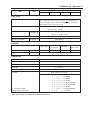
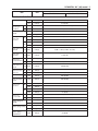
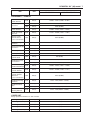
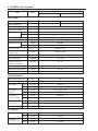
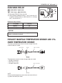
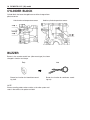
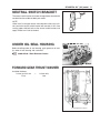
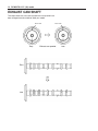
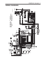
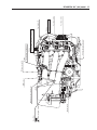
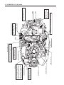
1
For '03 model
SUPPLEMENTARY SERVICE MANUAL
99501-87J20-01E
DF40/50 “K3” (2003) MODEL
FOREWORD
This supplementary service manual describes the outline, technical data and servicing procedures
for the “K3” (2003) models outboard motor.
Please read and thoroughly familiarize yourself with this information before using it for your service
activities.
NOTE:
Use this supplement with the following service manual:
DF40/50 Service Manual ( P/no, 99500-87J0 • -01E)
CONTENTS
SPECIFICATIONS ___________________________________________
SERVICE DATA _____________________________________________
ECM MAIN RELAY ___________________________________________
EXHAUST MANIFOLD TEMPERATURE SENSOR AND
CYLINDER TEMPERATURE SENSOR ___________________________
CYLINDER BLOCK __________________________________________
BUZZER ___________________________________________________
NEUTRAL SWITCH BRACKET _________________________________
UNDER OIL SEAL HOUSING __________________________________
FORWARD GEAR THRUST WASHER ___________________________
EXHAUST CAM SHAFT _______________________________________
WIRING DIAGRAMS _________________________________________
WIRE ROUTING _____________________________________________
2
4
9
9
10
10
11
11
11
12
13
14
2 DF40/DF50 “K3” (‘03) model
GENERAL INFORMATION
SPECIFICATIONS
Item
Unit
Data
DF40QH
DF40T
PRE-FIX
DF50T/50WT
04001F
DF50WQH
05001F
DIMENSIONS & WEIGHT
Overall length (front to back)
mm (in)
756 (29.8)
852 (33.5)
756 (29.8)
852 (33.5)
Overall width (side to side)
mm (in)
382 (15.0)
382 (15.0)
382 (15.0)
382 (15.0)
S
mm (in)
1263 (49.7)
—
1263 (49.7)
—
L
mm (in)
1390 (54.7)
1390 (54.7)
1390 (54.7)
1390 (54.7)
UL
mm (in)
—
—
1517 (59.7)
1517 (59.7)
Weight
S
kg (Ibs)
106 (234)
—
106 (234)
—
(without engine oil)
L
kg (Ibs)
109 (240)
110 (243)
109 (240)
110 (243)
UL
kg (Ibs)
—
—
112 (247)
113 (249)
S
mm (in. type)
401 (15)
—
401 (15)
—
L
mm (in. type)
528 (20)
528 (20)
528 (20)
528 (20)
UL
mm (in. type)
—
—
655 (25)
655 (25)
Overall height
Transom height
PERFORMANCE
kW (PS)
29.4 (40)
36.8 (50)
Recommended operating range
r/min
5200 – 5800
5900 – 6500
Idle speed
r/min
Maximum output
850 ± 50 (in-gear: approx. 850)
POWERHEAD
Engine type
4-stroke DOHC
Number of cylinders
3
Bore
mm (in)
71.0 (2.80)
Stroke
mm (in)
68.6 (2.70)
3
Total displacement
cm (cu in)
815 (49.7)
Compression ratio
:1
10
NGK
DCPR6E
Spark plug
Ignition system
Fuel supply system
Full-transistorized ignition
Multi-point sequential electronic fuel injection
Exhaust system
Through prop exhaust
Cooling system
Water cooled
Lubrication system
Wet sump by trochoid pump
Starting system
Throttle control
Electric
Remote control
Twist grip
Remote control
Twist grip
DF40/DF50 “K3” (‘03) model 3
Item
Unit
Data
DF40QH
DF40T
DF50WQH
DF50T/50WT
FUEL & OIL
Suzuki highly recommends that you use alcohol-free unleaded gasoline
with a minimum pump octane rating of 87 ( R 2+ M method) or 91
(Research method). However, blends of unleaded gasoline and alcohol
with equivalent octane content may be used.
Fuel
Engine oil
API classification
SE, SF, SG, SH, SJ
Viscosity rating 10W-40
Engine oil amounts
2.2 (2.3/1.9) : Oil change only
L (US/Imp. qt)
2.4 (2.5/2.1) : Oil filter change
Gear oil
Gearcase oil capacity
SUZUKI Outboard Motor Gear Oil (SAE #90 hypoid gear oil)
ml (US/Imp. oz)
610 (20.6/21.5)
BRACKET
Trim angle
Number of trim position
Maximum tilt angle
PTT system
Adjustable
Manual trim and gas
PTT system
assisted tilt system
5
PTT system
degree
PTT system
Manual trim and gas
assisted tilt system
5
73°
LOWER UNIT
Reversing system
Transmission
Gear
Forward-Neutral-Reverse
Reduction system
Bevel gear
Gear ratio
11 : 25 (2.27)
Drive line impact protection
Propeller
S
: Aluminum propeller
SS : Stainless steel propeller
These specifications are subject to change without notice.
Spline drive rubber hub
Blade × Diam. (in) × Pitch (in)
3
×
11-1/2
×
3
3
3
3
×
×
×
×
11-1/2
11-1/2
11-5/8
11-1/2
×
×
×
×
10
11
12
13
(S1000)
(S1100)
(S1200)
(S1301, SS1300)
3
3
3
3
×
×
×
×
11-3/8
11-1/4
11-1/8
11
×
×
×
×
14
15
16
17
(S1400, SS1400)
(S1500)
(S1600, SS1600)
(S1700)
9 (S900)
4 DF40/DF50 “K3” (‘03) model
SERVICE DATA
Item
Data
Unit
DF40T/40QH
DF50T/50WT/50WQH
POWERHEAD
Recommended operating range
Idle speed
*Cylinder compression
*Cylinder compression max.
difference between any other
cylinders
*Engine oil pressure
r/min
r/min
kPa (kg/cm2, psi)
kPa (kg/cm2, psi)
5200 – 5800
5900 – 6500
850 ± 50 (in-gear: approx.850)
1300 – 1600 (13 – 16, 185 – 228)
100 (1.0, 14)
300 – 380 (3.0 – 3.8, 43 – 54) at 4000 r/min
(at normal operating temp.)
kPa (kg/cm2, psi)
API classification SE, SF, SG, SH, SJ
Viscosity rating
SAE 10W-40
2.2 (2.3/1.9) : Oil change only
Engine oil
Engine oil amounts
L (US/Imp. qt)
Thermostat operating
temperature
2.4 (2.5/2.1) : Oil filter change
°C (°F)
58 – 62 (136 – 144)
* Figures shown are guidelines only, not absolute service limits.
ENGINE OIL PUMP
Radial clearance
Limit
mm (in)
0.31 (0.012)
Side clearance
Limit
mm (in)
0.15 (0.006)
CYLINDER HEAD/CAMSHAFT
Cylinder head distortion
Limit
mm (in)
0.05 (0.002)
Manifold seating faces
distortion
Limit
mm (in)
0.10 (0.004)
Cam height
IN
EX
Camshaft journal oil
clearance
STD
mm (in)
37.530–37.690 (1.4776–1.4839)
38.230–38.390 (1.5051–1.5114)
Limit
STD
mm (in)
mm (in)
37.430 (1.4736)
37.740–37.900 (1.4858–1.4921)
38.130 (1.5012)
37.740–37.900 (1.4858–1.4921)
Limit
mm (in)
37.640 (1.4819)
37.640 (1.4819)
STD
mm (in)
0.045 – 0.087 (0.0018 – 0.0034)
Limit
mm (in)
0.120 (0.0047)
Camshaft
journal (housing) inside
diameter
Top,
2nd,
STD
mm (in)
23.000 – 23.021 (0.9055 – 0.9063)
3rd,
4th
Limit
mm (in)
23.171 (0.9122)
Camshaft
journal outside
diameter
Top,
STD
mm (in)
22.934 – 22.955 (0.9029 – 0.9037)
Limit
mm (in)
22.784 (0.8970)
Limit
STD
mm (in)
mm (in)
0.10 (0.004)
0.025 – 0.062 (0.0010 – 0.0024)
Limit
STD
STD
mm (in)
0.150 (0.0059)
mm (in)
mm (in)
26.959 – 26.975 (1.0614 – 1.0620)
27.000 – 27.021 (1.0630 – 1.0638)
2nd,
3rd,
4th
Camshaft runout
Cylinder head bore to
tappet clearance
Tappet outer diameter
Cylinder head bore
DF40/DF50 “K3” (‘03) model 5
Item
Unit
Data
DF40T/40QH
DF50T/50WT/50WQH
VALVE / VALVE GUIDE
IN
mm (in)
24.6 (0.97)
EX
mm (in)
21.5 (0.85)
STD
mm (in)
0.18 – 0.24 (0.007 – 0.009)
STD
mm (in)
0.18 – 0.24 (0.007 – 0.009)
IN
degree
30°, 45°
EX
degree
15°, 45°
STD
mm (in)
0.020 – 0.047 (0.0008 – 0.0019)
Limit
mm (in)
0.070 (0.0028)
STD
mm (in)
0.045 – 0.072 (0.0018 – 0.0028)
Limit
mm (in)
0.090 (0.0035)
Valve guide inside
IN,EX
diameter
STD
mm (in)
5.500 – 5.512 (0.2165 – 0.2170)
Valve guide
protrusion
STD
mm (in)
11.0 (0.43)
IN
Valve stem
outside diameter EX
STD
mm (in)
5.465 – 5.480 (0.2152 – 0.2157)
STD
mm (in)
5.440 – 5.455 (0.2142 – 0.2148)
Valve stem end
length
IN,EX
Limit
mm (in)
3.20 (0.126)
IN
Limit
mm (in)
0.14 (0.006)
EX
Limit
mm (in)
0.18 (0.007)
Valve stem runout IN,EX
Limit
mm (in)
0.05 (0.002)
Valve head radial
IN,EX
runout
Limit
mm (in)
0.08 (0.003)
STD
mm (in)
1.0 (0.04)
Limit
mm (in)
0.7 (0.03)
STD
mm (in)
1.15 (0.045)
Limit
mm (in)
0.5 (0.02)
IN
STD
mm (in)
1.80 – 2.20 (0.071 – 0.087)
EX
STD
mm (in)
1.65 – 2.05 (0.065 – 0.081)
Valve diameter
Tappet clearance IN
(Cold engine
EX
condition)
Valve seat
angle
Valve guide to
valve stem
clearance
IN
EX
IN,EX
Valve stem end
deflection
Valve head
thickness
IN
EX
Valve seat
contact width
Valve spring free
length
STD
mm (in)
33.1 (1.30)
Limit
mm (in)
31.8 (1.25)
Valve spring tension
STD
N (kg, Ibs)
97 – 113 (9.7–11.3, 21.4–24.9) for 28.5 mm (1.12 in)
Limit
N (kg, Ibs)
89 (8.9, 19.6) for 28.5 mm (1.12 in)
Limit
mm (in)
2.0 (0.08)
Valve spring
squareness
6 DF40/DF50 “K3” (‘03) model
Item
Unit
Data
DF40T/40QH
DF50T/50WT/50WQH
CYLINDER/PISTON/PISTON RING
Cylinder distortion
Limit
mm (in)
0.060 (0.0024)
Piston to cylinder
clearance
STD
mm (in)
0.020 – 0.040 (0.0008 – 0.0016)
Limit
mm (in)
0.100 (0.0039)
Cylinder bore
STD
mm (in)
71.000 – 71.020 (2.7953 – 2.7961)
mm (in)
50 (2.0) from cylinder top surface
mm (in)
70.970 – 70.990 (2.7941 – 2.7949)
mm (in)
19 (0.7) from piston skirt end
Limit
mm (in)
0.100 (0.0039)
STD
mm (in)
0.10 – 0.25 (0.004 – 0.010)
Limit
mm (in)
0.70 (0.028)
STD
mm (in)
0.25 – 0.40 (0.010 – 0.016)
Limit
mm (in)
1.00 (0.039)
STD
mm (in)
Approx. 7.5 (0.30)
Limit
mm (in)
6.0 (0.24)
STD
mm (in)
Approx. 11.0 (0.43)
Limit
mm (in)
8.8 (0.35)
STD
mm (in)
0.02 – 0.06 (0.001 – 0.002)
Limit
mm (in)
0.10 (0.004)
STD
mm (in)
0.02 – 0.06 (0.001 – 0.002)
Limit
mm (in)
0.10 (0.004)
1st
STD
mm (in)
1.01 – 1.03 (0.040 – 0.041)
2nd
STD
mm (in)
1.01 – 1.03 (0.040 – 0.041)
Oil
STD
mm (in)
2.01 – 2.03 (0.079 – 0.080)
1st
STD
mm (in)
0.97 – 0.99 (0.038 – 0.039)
2nd
STD
mm (in)
0.97 – 0.99 (0.038 – 0.039)
STD
mm (in)
0.006 – 0.018 (0.0002 – 0.0007)
Limit
mm (in)
0.040 (0.0016)
STD
mm (in)
17.996 – 18.000 (0.7085 – 0.7087)
Limit
mm (in)
17.980 (0.7079)
STD
mm (in)
18.006 – 18.014 (0.7089 – 0.7092)
Limit
mm (in)
18.040 (0.7102)
STD
mm (in)
0.003 – 0.015 (0.0001 – 0.0006)
Limit
mm (in)
0.050 (0.0020)
STD
mm (in)
18.003 – 18.011 (0.7088 – 0.7091)
Cylinder measuring position
Piston skirt diameter
STD
Piston measuring position
Cylinder bore wear
Piston ring
end gap
1st
2nd
Piston ring
free end gap
1st
2nd
Piston ring to
groove
clearance
1st
2nd
Piston ring
groove width
Piston ring
thickness
Pin clearance in
piston pin hole
Piston pin outside
diameter
Piston pin hole
diameter
Pin clearance in
conrod small end
Conrod small end
bore
DF40/DF50 “K3” (‘03) model 7
Item
Unit
Data
DF40T/40QH
DF50T/50WT/50WQH
CRANKSHAFT / CONROD
Conrod small end
inside diameter
STD
mm (in)
18.003 – 18.011 (0.7088 – 0.7091)
STD
mm (in)
0.020 – 0.040 (0.0008 – 0.0016)
Limit
mm (in)
0.065 (0.0026)
Conrod big end
inside diameter
STD
mm (in)
41.000 – 41.018 (1.6142 – 1.6149)
Crank pin outside
diameter
STD
mm (in)
37.982 – 38.000 (1.4954 – 1.4961)
Crank pin outside
diameter difference
(out of round and taper)
Limit
mm (in)
0.010 (0.0004)
Conrod bearing
thickness
STD
mm (in)
1.486 – 1.502 (0.0585 – 0.0591)
Conrod big end oil
clearance
Conrod big end side
clearance
STD
mm (in)
0.100 – 0.250 (0.0039 – 0.0098)
Limit
mm (in)
0.350 (0.0138)
Conrod big end width
STD
mm (in)
21.950 – 22.000 (0.8642 – 0.8661)
Crank pin width
STD
mm (in)
22.100 – 22.200 (0.8700 – 0.8740)
Crankshaft center
journal runout
Limit
mm (in)
0.04 (0.002)
STD
mm (in)
0.020 – 0.040 (0.0008 – 0.0016)
Limit
mm (in)
0.065 (0.0026)
Crankcase bearing
holder inside diameter
STD
mm (in)
49.000 – 49.018 (1.9291 – 1.9298)
Crankshaft journal
outside diameter
STD
mm (in)
44.982 – 45.000 (1.7709 – 1.7717)
Limit
mm (in)
0.010 (0.0004)
STD
mm (in)
1.999 – 2.015 (0.0787 – 0.0793)
STD
mm (in)
0.11 – 0.31 (0.004 – 0.012)
Limit
mm (in)
0.35 (0.014)
STD
mm (in)
2.470 – 2.520 (0.0972 – 0.0992)
Crankshaft journal
oil clearance
Crankshaft journal
outside diameter
difference
(out of round and taper)
Crankshaft bearing
thickness
Crankshaft thrust
play
Crankshaft thrust
bearing thickness
LOWER UNIT
Design specification thickness for shim & washer
Pinion gear back-up shim
mm (in)
1.0 (0.04)
Forward gear back-up shim
mm (in)
1.0 (0.04)
Forward gear thrust washer
mm (in)
2.0 (0.08)
Reverse gear thrust washer
mm (in)
2.0 (0.08)
Reverse gear back-up shim
mm (in)
1.0 (0.04)
8 DF40/DF50 “K3” (‘03) model
Item
Unit
Data
DF40T/40QH
DF50T/50WT/50WQH
Degrees at r/min
ATDC 1° – BTDC 27°
ATDC 1° – BTDC 24°
r/min
6500
7000
ELECTRICAL
Ignition timing
Over revolution limiter
CKP sensor resistance
Ω at 20°C
168 – 252
CMP sensor resistance
Ω at 20°C
——
Ignition coil resistance Primary
Ω at 20°C
1.9 – 2.5
k Ω at 20°C
8.1 – 11.1
Ω at 20°C
0.56 – 0.84
Watt
216
Type
NGK
DCPR6E
Gap
mm (in)
0.8 – 0.9 (0.031 – 0.035)
A
Main fuse : 30
Ah (kC)
70 (252) or larger
Fuel injector resistance
Ω at 20°C
11.0 – 16.5
IAC valve resistance
Ω at 20°C
21.5 – 32.3
k Ω at 25°C
1.8 – 2.3
ECM main relay resistance
Ω at 20°C
80 – 120
Starter motor relay resistance
Ω at 20°C
3.5 – 5.1
PTT motor relay resistance
Ω at 20°C
3.0 – 4.5
Max. continuous time of use
Sec.
30
Motor output
kW
0.9
STD
mm (in)
17.0 (0.67)
Limit
mm (in)
10.0 (0.39)
STD
mm (in)
0.5 – 0.8 (0.02 – 0.03)
Limit
mm (in)
0.2 (0.01)
STD
mm (in)
33.0 (1.30)
Limit
mm (in)
32.0 (1.26)
Secondary
Battery charge coil resistance
Battery charge coil output (12V)
Standard spark plug
Fuse amp. rating
Recommended battery
capacity (12V)
IAT sensor/Cylinder temp. sensor
/ Ex-mani. temp. sensor
(Thermistor characteristic)
STARTER MOTOR
Brush length
Commutator
undercut
Commutator
outside diameter
Commutator outside
diameter difference
STD
mm (in)
0.05 (0.002)
Limit
mm (in)
0.40 (0.016)
Pinion to ring gear gap
STD
mm (in)
3.0 – 5.0 (0.12 – 0.20)
STD
mm (in)
9.8 (0.39)
Limit
mm (in)
4.8 (0.19)
STD
mm (in)
22.0 (0.87)
Limit
mm (in)
21.0 (0.83)
PTT MOTOR
Brush length
Commutator
outside diameter
DF40/DF50 “K3” (‘03) model 9
ECM MAIN RELAY
1 23
! 09930-99320 : Digital tester
12V
" Tester range : # (Continuity)
(1) Disconnect ECM main relay from wire.
(2) Check continuity between terminal 1 and 2 each time 12 V
is applied. Connect positive (+) side to terminal 4, and negative (–) side to terminal 3.
ECM main relay
4
ECM main relay function :
12 V power
Continuity
Applied
Yes
Not applied
No
$
Be careful not to touch 12 V power supply wires to each
other or with other terminals.
EXHAUST MANIFOLD TEMPERATURE SENSOR AND CYLINDER TEMPERATURE SENSOR
The shape of temperature sensor has been changed. from the
middle of 2002 year model.
O-ring
Tube color: Gray
14 mm
Dome shape
12 mm
The temperature sensor has been changed 2003 year model.
• Change of connector
• Elimination of O-ring
Tube color: Green
• Change of tube color
NOTE:
Exhaust manifold temperature sensor does not contact with cooling water from 2003 year model.
10 DF40/DF50 “K3” (‘03) model
CYLINDER BLOCK
Cylinder block has been changed because of the change of temperature sensor.
Hole for exhaust temperature sensor
Hole for cylinder temperature sensor
2002: Ê 12
2003: Ê 9
2002: Ê 12
2003: Ê 9
BUZZER
Buzzer in the remote control box (side-mount-type) has been
changed in function and shape.
Early
Buzzer has function for intermittent sounding itself.
Late
Buzzer has function for continuous sounding only.
NOTE:
Buzzer sounding pattern when caution or the other system activates is the same as the pattern on 2002.
DF40/DF50 “K3” (‘03) model 11
NEUTRAL SWITCH BRACKET
The neutral switch bracket has been changed to be secured with
two bolt from the middle of 2002 year model.
NOTE:
When install a late type neutral switch bracket to the early cylinder, secure the neutral switch bracket with one bolt. In this case
use the upper side bolt hole on the neutral switch bracket, and
apply Thread Lock 1342 to the bolt.
UNDER OIL SEAL HOUSING
Before installing under oil seal housing, apply grease to oil seal
lip, under oil seal housing and crankshaft.
% 99000-25160 : Water Resistant Grease
FORWARD GEAR THRUST WASHER
Available thickness
2.0 mm and 2.2 mm
Early
→
2.0 mm only
Late
Forward gear thrust washer
12 DF40/DF50 “K3” (‘03) model
EXHAUST CAM SHAFT
The shape of exhaust cam shaft and exhaust cam sprocket have
been changed from the middle of 2002 year model.
Arrow mark
Early
Early
Late
Arrow mark
Exhaust cam sprocket
Late
R/W
B/Y
O/B
OR
Gr
Gr
IGNITION COILS
G
Bl
O
Gr
P
B/W
R/B
Lb
Lbl
B/W
#3
#2
#1
ECM MAIN
RELAY
R/B
O/G
+
B/W
B/W
Gr
CMP SENSOR
RECTIFIER & REGULATOR
EX-MANI TEMP
SENSOR
V/W
Y/W
#3
Gr
B
#2
Gr
V
Y
#1
Gr
FUEL INJECTOR
W/R
P
Lb
Lbl
W/R
FP
W
B
P/B
B
V
B/W
W/B
Lg/W
B
B
B
B
R
Bl
7
Y
Y
Y
R
W
B/W
W
W
W
W
CKP SENSOR
W
6
CAP
FUSE 30A
ALTERNATOR
4
COMMUNICATION
CONNECTOR
ENGINE CONTROL MODULE
V/W
R/B
P/B
Gr
O/Y
B/G
Y
Bl
R
W
Lg/B
Lg/R
Bl/B
G/Y
P
G/W
O
Y/B
Bl/R
Bl/W
B/R
Br
Y
Gr
B/W
O/Y
B/G
B
Gr
Lg/W
O/G
B
B
B
B
B/W
O/B
B/Y
R/W
G
O
Bl
Br
M
PTT MOTOR
M
Y/G
P
Lb
Lbl
G
Bl
R
B
Y/G
B
W
3
W
R
Y/G
+
B
–
B
B
B
B
B/W
B
B
B
B
BATTERY 12V 70AH
Y/G
P
Lb
Lbl
W
2
1
B
W
STARTER
MOTOR
Lg/R
Gr
B
W
Y/B
G/Y
G/W
Lb
Lbl
Lg/B
Bl/R
Bl/W
P
O
Br
Bl/B
P
Gr
Y/G
B/R
B/W
G
G
Gr
W/R
Br
G
Bl
O
Lbl
Lb
B
O
P
O
Lg
B
P
O
Gr
B
TRIM SENDER
Y
Gr
B
W
P
P
Gr
IAT SENSOR
IAC VALVE
W-TUBE
UP
DN
Bl
Br
O
W
G
Br
5
Bl
4
BZ
Gr
P
Gr
B
B
O
P
O
Or
Gr
B
Gr
PTT SWITCH
Bl/B
P
P
Gr
Lg
Br
B
BUZZER
CANCEL
O
IG
Gr
START
BATT
W
Br
GND
STOP
B
G
B
W
R
Gr
P
TURN
B
Y
Gr
PUSH
B
Gr
Gr
Gr
Y
R/G
B
Gr
B
METER
ILLUMINATION
SWITCH
IGNITION SWITCH
B
R
Gr
Y
B
Lb
Lbl
P
W
Y
B
Bl-TUBU
W-TUBU
Gr
Bl-TUBE
Gr
B
Gr
B
R/G
B
Gr
B
Gr
B
R/G
B
Gr
B
..........Optional oarts
Lb
Lbl
R/G
B
MONITOR
TACHOMETER
TRIM
METER
REMOTE CONTROL BOX
DN
UP
G/Y
G/W
O
Or
B
METER
R/G
B
5 CAUTION BUZZER
(OVERHEAT/OIL PRESSURE/
BATTERY VOLTAGE/DIAGNOSIS)
6 BATTERY CHARGE COIL
OIL
PRESSURE SWITCH
7
1.0kgf/cm2 or less
ON
PTT SWITCH
PTT MOTOR RELAY UP
PTT MOTOR RELAY DN
STARTER MOTOR RELAY
NEUTRAL SWITCH
N
ON
F.R OFF
CTP SWITCH
1
2
3
4
Lbl
Lb
Br
Gr
W
P
P
Lb
Lbl
CYLINDER TEMP
SENSOR
Gr
Gr
Gr
IG
UP
OFF
DN
FREE
HIGH PRESSURE
FUEL PUMP
PUSH
B
R/G
B
R/G
MAP SENSOR
START
R/G
R/G
PTT SWITCH
DF40/DF50 “K3” (‘03) model 13
WIRING DIAGRAMS
"QH" MODEL
Rectifier & regulator
Exhaust manifold
temp. sensor
Install holder cover to
holder hook securely.
Electric parts holder cover
Engine wiring harness
Clamp
ECM main relay
Starter motor sub cable
PTT motor cable
Starter motor relay
Battery cable
PTT relay plate
PTT motor relay (DOWN)
PTT motor relay (UP)
Communication connector / cap
30A Fuse
14 DF40/DF50 “K3” (‘03) model
WIRE ROUTING
Neutral switch
3N·m (0.3 kg-m, 2.0 lb-ft)
Gas filter
Clip
MAP sensor hose / Protector
MAP sensor
PTT switch lead connector
Fuel injector #1
Fuel injector #3
Fuel injector #2
Fix injector lead wire.
Clamp
Fix fuel pump lead wire and fuel hose.
Clamp
Fix neutral switch lead wire.
Clamp
Oil pressure switch
DF40/DF50 “K3” (‘03) model 15
Battery charge coil
Starter motor
Fix lead wire not to contact
with flywheel magneto.
Clamp
Electric parts holder
Electric parts holder cover
MAP sensor bracket
After installing flywheel magneto and
securing nut with specified torque,
check air gap between CKP sensor
and reluctor bars on flywheel magneto.
Air gap : 0.75 mm (0.030 in)
CKP sensor
Fix lead wire not to contact
with flywheel magneto.
Clamp
MAP sensor
Clean thread of sensor and cylinder block with
cleaning solvent, when installing sensor.
Cylinder temp. sensor
Clamp
Fix engine wiring
harness not to contact
with oil filler cap.
Clamp
Clamp
Fix engine wiring harness not
to contact with hose crip.
Fix lead wires not to contact with flywheel magneto.
Clamp
Rectifier & regulator
Apply engine oil to O-ring
when installing sensor.
Exhaust manifold temp. sensor
16 DF40/DF50 “K3” (‘03) model
DF40/DF50 “K3” (‘03) model 17
Starter motor
Tighten bolt with PTT relay
ground wire, battery cable
ground wire and harness
ground wire.
CTP switch
Starter motor sub cable
Grommet
IAT sensor
IAC valve
Engine wiring harness
Route engine wiring harness
on battery cable .
-
Battery cable
Battery cable
Route battery cable on fuel hose.
Clamp
Clamp
Ignition coil #1
Clamp
CMP sensor
Ignition coil #2
Clip
Position clip tabs
inward (engine side)
Clamp
Ignition coil #3
Prepared by
Marine & Power Products Division
July, 2002
Manual No. 99501-87J20-01E
Printed in Japan
20
Printed in Japan
K3