1
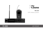
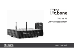
IEM 100
UHF wireless system
user manual
Musikhaus Thomann e.K.
Treppendorf 30
96138 Burgebrach
Germany
Telephone: +49 (0) 9546 9223-0
E-mail: [email protected]
Internet: www.thomann.de
23.02.2015, ID: 269815
Table of contents
Table of contents
1
General notes............................................................................................................................................... 5
2
Safety instructions..................................................................................................................................... 7
3
Features and scope of delivery......................................................................................................... 11
4
Installation and starting up................................................................................................................
4.1 General information........................................................................................................................
4.2 Transmitter.........................................................................................................................................
4.3 Receiver...............................................................................................................................................
4.4 Taking the system into operation..............................................................................................
5
Components and functions ............................................................................................................... 22
5.1 Transmitter......................................................................................................................................... 22
5.2 Receiver............................................................................................................................................... 27
6
Operating.................................................................................................................................................... 32
6.1 Setting up the transmitter............................................................................................................ 32
6.2 Setting up the receiver................................................................................................................... 35
7
Troubleshooting...................................................................................................................................... 38
15
15
17
20
21
IEM 100
3
Table of contents
8
Technical specifications.......................................................................................................................
8.1 Transmitter.........................................................................................................................................
8.2 Receiver...............................................................................................................................................
8.3 Frequency charts..............................................................................................................................
9
Protecting the environment.............................................................................................................. 54
UHF wireless system
4
41
41
42
43
General notes
1
General notes
This user manual contains important information on safe operation of the device. Read and
follow all safety notes and all instructions. Save this manual for future reference. Make sure
that it is available to all persons using this device. If you sell the device to other users, be sure
that they also receive this manual.
Our products are subject to a process of continuous development. We therefore reserve the
right to make changes without notice.
Symbols and signal words
This section provides an overview of the symbols and signal words used in this user manual.
IEM 100
5
General notes
Signal word
Meaning
DANGER!
This combination of symbol and signal word indicates an
immediate dangerous situation that will result in death or
serious injury if it is not avoided.
CAUTION!
This combination of symbol and signal word indicates a pos‐
sible dangerous situation that can result in minor injury if it
is not avoided.
NOTICE!
This combination of symbol and signal word indicates a pos‐
sible dangerous situation that can result in material and
environmental damage if it is not avoided.
Warning signs
Type of danger
Warning – danger zone.
UHF wireless system
6
Safety instructions
2
Safety instructions
Intended use
This device is intended to be used for the wireless transmission of audio signals to earplugs.
Use the device only as described in this user manual. Any other use or use under other oper‐
ating conditions is considered to be improper and may result in personal injury or property
damage. No liability will be assumed for damages resulting from improper use.
This device may be used only by persons with sufficient physical, sensorial, and intellectual
abilities and having corresponding knowledge and experience. Other persons may use this
device only if they are supervised or instructed by a person who is responsible for their safety.
Safety
DANGER!
Danger for children
Ensure that plastic bags, packaging, etc. are disposed of properly and are not
within reach of babies and young children. Choking hazard!
Ensure that children do not detach any small parts (e.g. knobs or the like) from
the unit. They could swallow the pieces and choke!
Never let children unattended use electrical devices.
IEM 100
7
Safety instructions
CAUTION!
Possible hearing impairment
The use of earphones at high volume over a longer period of time can cause per‐
manent hearing damage.
Adjust the output volume of your audio device to a medium value and use the
earphones no longer than about one hour a day.
NOTICE!
Operating conditions
This device has been designed for indoor use only. To prevent damage, never
expose the device to any liquid or moisture. Avoid direct sunlight, heavy dirt, and
strong vibrations.
UHF wireless system
8
Safety instructions
NOTICE!
External power supply
The device is powered by an external power supply. Before connecting the
external power supply, ensure that the input voltage (AC outlet) matches the
voltage rating of the device and that the AC outlet is protected by a residual cur‐
rent circuit breaker. Failure to do so could result in damage to the device and pos‐
sibly the user.
Unplug the external power supply before electrical storms occur and when the
device is unused for long periods of time to reduce the risk of electric shock or
fire.
NOTICE!
Risk of fire due to incorrect polarity
Incorrectly inserted batteries may destroy the device or the batteries.
Ensure that proper polarity is observed when inserting batteries.
IEM 100
9
Safety instructions
NOTICE!
Possible damage by leaking batteries
Leaking batteries can cause permanent damage to the device.
Take batteries out of the device if it is not going to be used for a longer period.
UHF wireless system
10
Features and scope of delivery
3
Features and scope of delivery
The UHF wireless system IEM 100 is suitable for use as in-ear monitoring system especially for
professional events, on rock stages and concert halls, theatres and musicals.
IEM 100
11
Features and scope of delivery
the t.bone IEM 100 770 MHz
(item no. 269815)
Your UHF wireless system IEM 100 consists of the following components:
n 9.5" stereo transmitter IEM 100 ST
– Very high sensitivity at very high signal-to-noise ratio
– Input: 2 × XLR/1/4" phone combo socket
– Headphones outlet (1/4" phone socket) with volume control
– Mounting option for two transmitters side by side in a 19" rack
– Operating voltage supply: DC 12 V
n Bodypack receiver IEM 100 R
– Earplug outlet (1/8" mini phone socket) with volume control
– Operating voltage supply: 2 × AA cells (LR6, 1.5 V)
n Earplugs EP 3
Ten systems can be operated simultaneously. The system operates within a frequency range of
768.000 MHz to 787.275 MHz, divided into 10 frequency groups. The frequency range is
intended for use in Germany with regard to LTE.
Included accessories: 12V AC adapter, mounting hardware for rack mounting, antenna-con‐
verter and plastic case.
UHF wireless system
12
Features and scope of delivery
the t.bone IEM 100 800 MHz
(item no. 137618)
Your UHF wireless system IEM 100 consists of the following components:
n 9.5" stereo transmitter IEM 100 ST
– Very high sensitivity at very high signal-to-noise ratio
– Input: 2 × XLR/1/4" phone combo socket
– Headphones outlet (1/4" phone socket) with volume control
– Mounting option for two transmitters side by side in a 19" rack
– Operating voltage supply: DC 12 V
n Bodypack receiver IEM 100 R
– Earplug outlet (1/8" mini phone socket) with volume control
– Operating voltage supply: 2 × AA cells (LR6, 1.5 V)
n Earplugs EP 3
Ten systems can be operated simultaneously. The system operates within a frequency range of
791.850 MHz to 813.225 MHz, divided into 10 frequency groups.
Included accessories: 12V AC adapter, mounting hardware for rack mounting, antenna-con‐
verter and plastic case.
IEM 100
13
Features and scope of delivery
the t.bone IEM 100 863 MHz
(item no. 137793)
Your UHF wireless system IEM 100 consists of the following components:
n 9.5" stereo transmitter IEM 100 ST
– Very high sensitivity at very high signal-to-noise ratio
– Input: 2 × XLR/1/4" phone combo socket
– Headphones outlet (1/4" phone socket) with volume control
– Mounting option for two transmitters side by side in a 19" rack
– Operating voltage supply: DC 12 V
n Bodypack receiver IEM 100 R
– Earplug outlet (1/8" mini phone socket) with volume control
– Operating voltage supply: 2 × AA cells (LR6, 1.5 V)
n Earplugs EP 3
Four systems can be operated simultaneously. The system operates within a frequency range
of 863.1 MHz to 864.4 MHz.
Included accessories: 12V AC adapter, mounting hardware for rack mounting, antenna-con‐
verter and plastic case.
UHF wireless system
14
Installation and starting up
4
Installation and starting up
4.1 General information
Unpack and carefully check that there is no transportation damage before using the unit. Keep
the equipment packaging. To fully protect the device against vibration, dust and moisture
during transportation or storage use the original packaging or your own packaging material
suitable for transport or storage, respectively.
Establish all connections as long as the unit is switched off. Use the shortest possible highquality cables for all connections.
IEM 100
15
Installation and starting up
Notes on wireless transmission
n This device utilizes frequencies that are not harmonized within the European Union (EU)
and therefore may only be used in certain EU member states. In all European countries, the
frequencies used for the transmission of audio signals are strictly regulated. Before you
start, make sure the frequencies are allowed in the respective country and check whether
the operation must be reported to the appropriate authority.
n Make sure that transmitter and receiver are both tuned to the same channel.
n Never set multiple transmitters to the same channel.
n Make sure that there are no metal objects between the transmitter and receiver.
n Avoid interference from other radio or in-ear systems.
UHF wireless system
16
Installation and starting up
4.2 Transmitter
XLR connections for signal input
on the transmitter
XLR/1/4" combo sockets for signal input on the transmitter. Drawing and table indicate the
XLR pin assignment (balanced wiring) as well as the pin assignment of a suitable 1/4" phone
plug.
1
Ground, shielding
2
Positive signal (+)
3
Negative signal (–)
IEM 100
17
Installation and starting up
Phone socket for headphones
outlet
Rack mounting
1
Signal
2
Ground, shielding
Drawing and table indicate the pin assignment of a 1/4" TRS phone plug to be used.
1
Signal (left)
2
Signal (right)
3
Ground, shielding
The unit has been designed for rack mounting in a standard 19-inch rack; it occupies one rack
unit.
UHF wireless system
18
Installation and starting up
Connecting the operating
supply voltage
NOTICE!
External power supply
The device is powered by an external power supply. Before connecting the
external power supply, ensure that the input voltage (AC outlet) matches the
voltage rating of the device and that the AC outlet is protected by a residual cur‐
rent circuit breaker. Failure to do so could result in damage to the device and pos‐
sibly the user.
Unplug the external power supply before electrical storms occur and when the
device is unused for long periods of time to reduce the risk of electric shock or
fire.
First, connect the power adapter to the transmitter and then plug the adapter into a mains
wall outlet.
IEM 100
19
Installation and starting up
Mounting the antenna
Attach the included antenna to the back of the transmitter. To improve the transmission
quality and for adaptation to the specific spatial conditions the antenna can be rotated and
swivelled.
If there is not enough space for the direct mounting of the antenna on the unit, e.g. due to
limited space in the rack, you can use the supplied coaxial cable to mount the antenna apart
from the unit. Therefore use the BNC adapter.
Putting the audio connection
into operation
Connect the audio inputs of the transmitter to suitable line outputs of your mixing console or
amplifier. Slide the level adjustment switch (11) to the ‘–12 dB’ position. Set the input sensi‐
tivity control (2) to a middle position first.
To achieve best sound quality, a fine adjustment of this control may be required. If the input
level is too low slide the level adjustment switch (11) to the ‘0 dB’ position.
4.3 Receiver
Inserting batteries into the
receiver
Press on the snap-in locks at the side to open the battery compartment (18). Flip the lid open
and insert the batteries respecting the correct polarity. Close the battery compartment and
switch the transmitter on. The ‘RF’ LED (22) briefly lights up.
UHF wireless system
20
Installation and starting up
4.4 Taking the system into operation
n Make sure that the receiver is switched off, the main switch (14) is set to the ‘OFF’ position.
n Attach the receiver with the clip to your belt or guitar strap.
n Insert the earplugs into the ear canal carefully and observe the markings ‘L’ and ‘R’ for left
and right sides.
n Turn the transmitter and the receiver on and test the transmission. Make sure that both
transmitter and receiver are set to the same frequency group and the same channel. If nec‐
essary, adjust the volume on the receiver, the input sensitivity of the transmitter and the
levels on your mixer or amp.
IEM 100
21
Components and functions
5
Components and functions
5.1 Transmitter
Front panel of the transmitter
UHF wireless system
22
Components and functions
1 POWER
Main switch to turn the device on or off. For turning on, keep this button pressed for one second.
2 INPUT LEVEL
Control for adjusting the input sensitivity.
3 Display
4 SET
Enter button for menu control.
5
/
Buttons for increasing / decreasing the currently indicated value.
6 PHONES
Headphones socket.
7 VOLUME
Headphones volume control.
IEM 100
23
Components and functions
Rear panel of the transmitter
UHF wireless system
24
Components and functions
8 DC INPUT
Connect the cable of the supplied mains adapter to this socket. If using another power adapter make sure it provides
the correct voltage, plug polarity and sufficient power.
9, 10 LEFT INPUT / RIGHT INPUT
XLR/1/4" combo sockets (left and right channel) for the direct connection to a mixing console or another audio
device that is used as signal source.
11 PAD
Level adjustment switch. Set this switch to the ‘–12 dB’ position to attenuate the input signals by 12 dB. In ‘0 dB‘ posi‐
tion, there is no attenuation.
Beneath, you find the indication of the frequency range, in which the unit operates. The specification here must
match the specification on the rear side of the receiver.
12 ANTENNA
BNC mounting socket for the supplied UHF antenna. Make sure the frequency indicated on the antenna matches the
frequency range indicated on the transmitter.
IEM 100
25
Components and functions
Display of the transmitter
A Limiter
Indicates limiter action as protection against volume peaks.
B Stereo/Mono
Indicates the selected operating mode (stereo or mono).
C Level indicator for left and right channel.
D
Indicates that the unit is locked to prevent unintentional operation.
E Indicates the frequency that is assigned to the set combination of frequency group
and channel (Ä Chapter 8.3 ‘Frequency charts’ on page 43).
F CHANNEL
Shows the selected channel.
G GROUP
Shows the selected frequency group.
UHF wireless system
26
Components and functions
5.2 Receiver
Front panel of the receiver
13 Flexible antenna.
14 ON/OFF/MAX
Main switch and volume control. Turn this knob clockwise past the point of resist‐
ance to turn on the receiver. Turn it further to increase the volume.
Turn this knob counter-clockwise to reduce the volume. Turn it further past the
point of resistance to turn off the receiver.
15 Display
16 SET
Enter button for menu control.
17 Battery compartment for two AA cells (LR6), 1.5 V or comparable rechargeable bat‐
teries.
18 Battery compartment lid.
IEM 100
27
Components and functions
19 ESC
Function „Cancel/EXIT“ in the menu.
20
/
Buttons for increasing / decreasing the currently indicated value. The balance is
regulated by pressing and holding the suitable key.
Top panel of the receiver
21 PHONES
1/8" mini phone socket (stereo) for the earplugs.
22 RF
This LED lights up on incoming radio signal.
UHF wireless system
28
Components and functions
Rear panel of the receiver
23 Indication of the frequency range in which the device operates. The specification
here must match the specification printed on the back of the transmitter.
24 Clip to attach the transmitter to your belt or guitar strap.
IEM 100
29
Components and functions
Display of the receiver
H GR
Indicates the selected frequency group.
I CH
Indicates the selected channel.
J LIM
Indicates Limiter action as protection against volume peaks.
K HF
Indicates the activated high frequency boost function.
L Battery level indicator. Replace the batteries when only one bar remains displayed.
M Radio signal strength indicator (one to five bars).
N ST
Indicates an incoming stereo signal.
UHF wireless system
30
Components and functions
O
Indicates that the unit is locked to prevent unintentional operation.
P Indicates the frequency that is assigned to the set combination of frequency group
and channel (Ä Chapter 8.3 ‘Frequency charts’ on page 43).
IEM 100
31
Operating
6
Operating
6.1 Setting up the transmitter
Selecting frequency group and
channel
Press the [SET] button repeatedly until the ‘GROUP’ field (frequency group) flashes in the dis‐
play. Use the ou buttons to increase or decrease the indicated value by one. When the
desired value is shown press the [SET] button to confirm the setting and proceed to the next
menu item.
Press the [SET] button repeatedly until the ‘CHANNEL’ field flashes in the display. Use the ou
buttons to increase or decrease the indicated value by one. When the desired value is shown
press the [SET] button to confirm the setting and proceed to the next menu item.
In the lower right area, the display shows the used transmission frequency in MHz, that is
assigned to the set combination of frequency group and channel (Ä Chapter 8.3 ‘Frequency
charts’ on page 43).
UHF wireless system
32
Operating
Transmitter and receiver must be set to the same combination of frequency group
and channel. If you use multiple wireless systems from this device family, for best
results you should assign all systems to the same frequency group, but give each
system a different channel.
Selecting the operating mode
Press the [SET] button repeatedly until the ‘Stereo’ or ‘Mono’ field flashes in the display. Use
the ou buttons to toggle between mono and stereo operation. When the desired mode is
shown, press the [SET] button for confirmation and to proceed to the next menu item.
IEM 100
33
Operating
Locking against changes
Press the [SET] button repeatedly until ‘ON’ or ‘OFF’ and the symbol are flashing in the dis‐
play. Use the ou buttons to toggle between locked status (display = ‘ON’ ) and normal
operation (display = ‘OFF’ ). In locked status, you can view the system settings, but you can't
change them. In this case the display shows the symbol.
Press the [SET] button to confirm the setting and proceed to the next menu item.
Adjusting the input level
The display shows the input level of the left and right channels in a bar display. Set the input
sensitivity control (2) so that signal peaks reach the ‘0 dB’ marking. If the input level is still too
low, slide the level adjustment switch (11) into the ‘0 dB’ position.
UHF wireless system
34
Operating
6.2 Setting up the receiver
The [SET] and [ESC] buttons that you need to set up the receiver are located behind
the battery compartment lid.
IEM 100
35
Operating
Selecting frequency group and
channel
Press the [SET] button repeatedly until the ‘GROUP’ field (frequency group) flashes in the dis‐
play. Use the ou buttons to increase or decrease the indicated value by one. When the
desired value is shown press the [SET] button to confirm the setting and proceed to the next
menu item. Press [ESC] to confirm the setting and exit the menu.
Press the [SET] button repeatedly until the ‘CHANNEL’ field flashes in the display. Use the ou
buttons to increase or decrease the indicated value by one. When the desired value is shown
press the [SET] button to confirm the setting and proceed to the next menu item. Press [ESC] to
confirm the setting and exit the menu.
In the lower area, the display shows the used transmission frequency in MHz, that is assigned
to the set combination of frequency group and channel (Ä Chapter 8.3 ‘Frequency charts’
on page 43).
Transmitter and receiver must be set to the same combination of frequency group
and channel. If you use multiple wireless systems from this device family, for best
results you should assign all systems to the same frequency group, but give each
system a different channel.
UHF wireless system
36
Operating
Turning on the treble boost
Press the [SET] button repeatedly until ‘ON’ or ‘OFF’ and the ‘HF’ field are flashing in the dis‐
play. Use the ou button to turn the treble boost function on or off (display = ‘ON’ or
‘OFF’ ). If this function is enabled, the frequencies above 10 kHz are boosted by 6 dB and the
display shows the ‘HF’ field. If the function is disabled, there's no treble boost.
Press the [SET] button to confirm the setting and proceed to the next menu item. Press [ESC] to
confirm the setting and exit the menu.
Locking the settings
Press the [SET] button repeatedly until ‘ON’ or ‘OFF’ and the symbol are flashing in the dis‐
play. Use the ou buttons to toggle between locked status (display = ‘ON’ ) and normal
operation (display = ‘OFF’ ). In locked status, you can view the system settings, but you can't
change them. In this case the display shows the symbol.
Press the [SET] button to confirm the setting and proceed to the next menu item. Press [ESC] to
confirm the setting and exit the menu.
IEM 100
37
Troubleshooting
7
Troubleshooting
In the following we list a few common problems that may occur during operation. We give you
some suggestions for easy troubleshooting:
UHF wireless system
38
Troubleshooting
Symptom
Remedy
No sound
1. Check the power supply of the transmitter and receiver.
2. Make sure that both transmitter and receiver operate in the same frequency
range and that the transmitting antenna is designed for this frequency range.
The frequency range is stated on the devices.
3. Are both transmitter and receiver set to the same frequency group and the
same channel?
4. Check the connection between the transmitter and the connected audio
device (amp, mixer). Is the connected audio device switched on and does the
output signal level of the audio device match the input sensitivity of the trans‐
mitter?
5. Try to improve the transmission by moving the receiver closer to the trans‐
mitter.
6. Make sure that no metal objects near the transmitter or receiver obstruct the
transmission.
Transmission is interrupted.
1. Modify the orientation of the antennas.
IEM 100
39
Troubleshooting
Symptom
Remedy
2. If you use more than one wireless system at the same time, check the used
frequency groups and channels.
3. Interference can also be caused by televisions, radios or mobile phones.
The sound is distorted.
Change the ‘INPUT LEVEL’ control setting on the transmitter.
If the procedures recommended above do not succeed, please contact our Service Center. You
can find the contact information at www.thomann.de.
UHF wireless system
40
Technical specifications
8
Technical specifications
8.1 Transmitter
Input
2 × XLR / 1/4" phone combo socket (balanced)
Headphones output
1/4" phone socket (stereo)
Modulation type
Frequency modulation (FM)
Transmission level
10 dBm
Input impedance
100 kΩ
Maximum audio input level
+12 dBV
Gain range
40 dB
NF frequency response
60 Hz…16 kHz (±3 dB)
THD
< 1 % @ 1 kHz
Dynamic range
> 90 dB (A-weighted)
IEM 100
41
Technical specifications
Operating voltage supply
DC 12…18 V , 300 mA, via supplied power adapter
Dimensions (W × D × H, without antenna)
212 mm × 160 mm × 44 mm
Weight
960 g
8.2 Receiver
Modulation type
Frequency modulation (FM)
Image rejection
> 55 dB
Sensitivity
–94 dBm @ 30 dB SINAD, typical
Audio output level
100 mW
Operating voltage supply
2 × AA cell (LR6, 1.5 V)
Dimensions (W × D × H, without antenna)
105 mm × 23 mm × 64 mm
Weight (without batteries)
100 g
UHF wireless system
42
Technical specifications
8.3 Frequency charts
the t.bone IEM 100 770 MHz (Item no. 269815)
Frequency group 1
Channel 1
Channel 2
Channel 3
Channel 4
Channel 5
Channel 6
Channel 7
Channel 8
768.000 MHz
768.625 MHz
768.975 MHz
769.350 MHz
770.175 MHz
771.125 MHz
772.725 MHz
773.375 MHz
Channel 9
Channel 10
Channel 11
Channel 12
Channel 13
Channel 14
Channel 15
Channel 16
774.525 MHz
775.075 MHz
777.050 MHz
778.675 MHz
780.100 MHz
783.325 MHz
784.175 MHz
787.950 MHz
Frequency group 2
Channel 1
Channel 2
Channel 3
Channel 4
Channel 5
Channel 6
Channel 7
Channel 8
768.125 MHz
769.875 MHz
770.300 MHz
771.250 MHz
772.250 MHz
773.500 MHz
774.650 MHz
775.200 MHz
Channel 9
Channel 10
Channel 11
Channel 12
Channel 13
Channel 14
Channel 15
Channel 16
777.175 MHz
778.800 MHz
780.225 MHz
781.400 MHz
783.450 MHz
785.475 MHz
786.375 MHz
787.700 MHz
IEM 100
43
Technical specifications
the t.bone IEM 100 770 MHz (Item no. 269815)
Frequency group 3
Channel 1
Channel 2
Channel 3
Channel 4
Channel 5
Channel 6
Channel 7
Channel 8
768.425 MHz
769.775 MHz
770.600 MHz
771.050 MHz
772.075 MHz
773.150 MHz
774.950 MHz
775.500 MHz
Channel 9
Channel 10
Channel 11
Channel 12
Channel 13
Channel 14
Channel 15
Channel 16
776.250 MHz
777.475 MHz
779.100 MHz
780.525 MHz
781.700 MHz
783.750 MHz
785.775 MHz
786.675 MHz
Frequency group 4
Channel 1
Channel 2
Channel 3
Channel 4
Channel 5
Channel 6
Channel 7
Channel 8
768.850 MHz
769.825 MHz
770.600 MHz
771.975 MHz
772.500 MHz
772.975 MHz
773.575 MHz
774.225 MHz
Channel 9
Channel 10
Channel 11
Channel 12
Channel 13
Channel 14
Channel 15
Channel 16
775.375 MHz
776.675 MHz
777.900 MHz
779.525 MHz
781.200 MHz
783.900 MHz
784.475 MHz
786.900 MHz
UHF wireless system
44
Technical specifications
the t.bone IEM 100 770 MHz (Item no. 269815)
Frequency group 5
Channel 1
Channel 2
Channel 3
Channel 4
Channel 5
Channel 6
Channel 7
Channel 8
769.125 MHz
769.750 MHz
770.475 MHz
771.300 MHz
772.250 MHz
773.850 MHz
774.500 MHz
775.650 MHz
Channel 9
Channel 10
Channel 11
Channel 12
Channel 13
Channel 14
Channel 15
Channel 16
776.200 MHz
776.950 MHz
778.175 MHz
779.800 MHz
781.475 MHz
783.325 MHz
784.175 MHz
787.175 MHz
Frequency group 6
Channel 1
Channel 2
Channel 3
Channel 4
Channel 5
Channel 6
Channel 7
Channel 8
769.450 MHz
770.075 MHz
770.800 MHz
771.625 MHz
772.075 MHz
773.575 MHz
774.825 MHz
775.975 MHz
Channel 9
Channel 10
Channel 11
Channel 12
Channel 13
Channel 14
Channel 15
Channel 16
776.525 MHz
777.275 MHz
778.500 MHz
780.125 MHz
781.550 MHz
782.725 MHz
784.775 MHz
785.625 MHz
IEM 100
45
Technical specifications
the t.bone IEM 100 770 MHz (Item no. 269815)
Frequency group 7
Channel 1
Channel 2
Channel 3
Channel 4
Channel 5
Channel 6
Channel 7
Channel 8
769.625 MHz
770.975 MHz
771.375 MHz
772.250 MHz
773.275 MHz
774.350 MHz
775.000 MHz
776.150 MHz
Channel 9
Channel 10
Channel 11
Channel 12
Channel 13
Channel 14
Channel 15
Channel 16
777.450 MHz
778.675 MHz
780.300 MHz
781.725 MHz
782.900 MHz
784.950 MHz
785.800 MHz
787.875 MHz
Frequency group 8
Channel 1
Channel 2
Channel 3
Channel 4
Channel 5
Channel 6
Channel 7
Channel 8
769.825 MHz
770.800 MHz
771.175 MHz
772.000 MHz
773.950 MHz
774.550 MHz
775.200 MHz
776.900 MHz
Channel 9
Channel 10
Channel 11
Channel 12
Channel 13
Channel 14
Channel 15
Channel 16
777.650 MHz
778.875 MHz
780.500 MHz
781.925 MHz
783.100 MHz
785.375 MHz
786.900 MHz
787.600 MHz
UHF wireless system
46
Technical specifications
the t.bone IEM 100 770 MHz (Item no. 269815)
Frequency group 9
Channel 1
Channel 2
Channel 3
Channel 4
Channel 5
Channel 6
Channel 7
Channel 8
770.350 MHz
771.325 MHz
772.100 MHz
773.475 MHz
774.475 MHz
775.725 MHz
776.875 MHz
777.425 MHz
Channel 9
Channel 10
Channel 11
Channel 12
Channel 13
Channel 14
Channel 15
Channel 16
778.175 MHz
779.400 MHz
781.025 MHz
782.700 MHz
784.750 MHz
785.600 MHz
786.775 MHz
787.675 MHz
Frequency group 10
Channel 1
Channel 2
Channel 3
Channel 4
Channel 5
Channel 6
Channel 7
Channel 8
770.725 MHz
771.700 MHz
772.475 MHz
773.850 MHz
774.850 MHz
775.450 MHz
776.100 MHz
777.250 MHz
Channel 9
Channel 10
Channel 11
Channel 12
Channel 13
Channel 14
Channel 15
Channel 16
777.800 MHz
778.550 MHz
779.775 MHz
781.850 MHz
783.025 MHz
784.425 MHz
786.350 MHz
787.275 MHz
IEM 100
47
Technical specifications
the t.bone IEM 100 800 MHz (Item no. 137618)
Frequency group 1
Channel 1
Channel 2
Channel 3
Channel 4
Channel 5
Channel 6
Channel 7
Channel 8
790.850 MHz
791.475 MHz
792.525 MHz
793.150 MHz
795.550 MHz
797.050 MHz
798.850 MHz
800.650 MHz
Channel 9
Channel 10
Channel 11
Channel 12
Channel 13
Channel 14
Channel 15
Channel 16
802.575 MHz
803.725 MHz
805.750 MHz
806.850 MHz
808.650 MHz
811.725 MHz
813.150 MHz
813.800 MHz
Frequency group 2
Channel 1
Channel 2
Channel 3
Channel 4
Channel 5
Channel 6
Channel 7
Channel 8
791.400 MHz
792.600 MHz
793.925 MHz
794.200 MHz
795.725 MHz
797.750 MHz
799.400 MHz
801.475 MHz
Channel 9
Channel 10
Channel 11
Channel 12
Channel 13
Channel 14
Channel 15
Channel 16
803.100 MHz
804.775 MHz
805.800 MHz
807.400 MHz
809.200 MHz
810.200 MHz
812.775 MHz
813.750 MHz
UHF wireless system
48
Technical specifications
the t.bone IEM 100 800 MHz (Item no. 137618)
Frequency group 3
Channel 1
Channel 2
Channel 3
Channel 4
Channel 5
Channel 6
Channel 7
Channel 8
790.875 MHz
791.450 MHz
792.550 MHz
793.175 MHz
795.575 MHz
797.075 MHz
798.875 MHz
801.100 MHz
Channel 9
Channel 10
Channel 11
Channel 12
Channel 13
Channel 14
Channel 15
Channel 16
802.550 MHz
803.700 MHz
805.775 MHz
806.875 MHz
808.625 MHz
811.700 MHz
813.175 MHz
813.775 MHz
Frequency group 4
Channel 1
Channel 2
Channel 3
Channel 4
Channel 5
Channel 6
Channel 7
Channel 8
792.625 MHz
793.100 MHz
793.450 MHz
793.950 MHz
795.025 MHz
797.300 MHz
799.425 MHz
800.625 MHz
Channel 9
Channel 10
Channel 11
Channel 12
Channel 13
Channel 14
Channel 15
Channel 16
804.800 MHz
805.250 MHz
807.475 MHz
808.550 MHz
809.975 MHz
810.325 MHz
811.600 MHz
813.300 MHz
IEM 100
49
Technical specifications
the t.bone IEM 100 800 MHz (Item no. 137618)
Frequency group 5
Channel 1
Channel 2
Channel 3
Channel 4
Channel 5
Channel 6
Channel 7
Channel 8
790.900 MHz
791.425 MHz
792.575 MHz
793.200 MHz
795.600 MHz
797.100 MHz
798.900 MHz
801.125 MHz
Channel 9
Channel 10
Channel 11
Channel 12
Channel 13
Channel 14
Channel 15
Channel 16
803.025 MHz
803.675 MHz
805.300 MHz
806.900 MHz
808.600 MHz
810.050 MHz
811.675 MHz
813.125 MHz
Frequency group 6
Channel 1
Channel 2
Channel 3
Channel 4
Channel 5
Channel 6
Channel 7
Channel 8
792.650 MHz
793.475 MHz
793.975 MHz
794.525 MHz
795.050 MHz
797.775 MHz
799.450 MHz
800.600 MHz
Channel 9
Channel 10
Channel 11
Channel 12
Channel 13
Channel 14
Channel 15
Channel 16
804.825 MHz
805.225 MHz
807.450 MHz
808.525 MHz
809.950 MHz
810.525 MHz
811.575 MHz
813.275 MHz
UHF wireless system
50
Technical specifications
the t.bone IEM 100 800 MHz (Item no. 137618)
Frequency group 7
Channel 1
Channel 2
Channel 3
Channel 4
Channel 5
Channel 6
Channel 7
Channel 8
790.925 MHz
793.225 MHz
794.100 MHz
795.625 MHz
797.125 MHz
798.925 MHz
801.150 MHz
802.175 MHz
Channel 9
Channel 10
Channel 11
Channel 12
Channel 13
Channel 14
Channel 15
Channel 16
803.050 MHz
803.650 MHz
805.275 MHz
806.925 MHz
808.575 MHz
810.025 MHz
811.650 MHz
813.100 MHz
Frequency group 8
Channel 1
Channel 2
Channel 3
Channel 4
Channel 5
Channel 6
Channel 7
Channel 8
794.000 MHz
794.300 MHz
794.575 MHz
795.100 MHz
796.775 MHz
797.800 MHz
800.525 MHz
802.000 MHz
Channel 9
Channel 10
Channel 11
Channel 12
Channel 13
Channel 14
Channel 15
Channel 16
803.600 MHz
805.200 MHz
807.425 MHz
809.125 MHz
809.950 MHz
811.550 MHz
812.800 MHz
813.250 MHz
IEM 100
51
Technical specifications
the t.bone IEM 100 800 MHz (Item no. 137618)
Frequency group 9
Channel 1
Channel 2
Channel 3
Channel 4
Channel 5
Channel 6
Channel 7
Channel 8
790.950 MHz
793.425 MHz
794.125 MHz
795.650 MHz
797.150 MHz
798.950 MHz
801.175 MHz
802.200 MHz
Channel 9
Channel 10
Channel 11
Channel 12
Channel 13
Channel 14
Channel 15
Channel 16
803.050 MHz
803.625 MHz
805.250 MHz
806.950 MHz
809.100 MHz
810.000 MHz
811.625 MHz
813.200 MHz
Frequency group 10
Channel 1
Channel 2
Channel 3
Channel 4
Channel 5
Channel 6
Channel 7
Channel 8
794.050 MHz
794.325 MHz
795.075 MHz
796.800 MHz
797.275 MHz
800.575 MHz
801.200 MHz
802.050 MHz
Channel 9
Channel 10
Channel 11
Channel 12
Channel 13
Channel 14
Channel 15
Channel 16
803.575 MHz
805.175 MHz
806.950 MHz
809.150 MHz
809.475 MHz
811.100 MHz
812.850 MHz
813.225 MHz
UHF wireless system
52
Technical specifications
the t.bone IEM 100 863 MHz (Item no. 137793)
Channel 1
Channel 2
Channel 3
Channel 4
Channel 5
Channel 6
Channel 7
Channel 8
863.100 MHz
863.900 MHz
864.500 MHz
864.900 MHz
863.200 MHz
863.300 MHz
863.400 MHz
863.500 MHz
Channel 9
Channel 10
Channel 11
Channel 12
Channel 13
Channel 14
Channel 15
Channel 16
863.600 MHz
863.700 MHz
863.800 MHz
864.000 MHz
864.100 MHz
864.200 MHz
864.300 MHz
864.400 MHz
IEM 100
53
Protecting the environment
9
Protecting the environment
Disposal of the packaging mate‐
rial
For the transport and protective packaging, environmentally friendly materials have been
chosen that can be supplied to normal recycling.
Ensure that plastic bags, packaging, etc. are properly disposed of.
Do not just dispose these materials with your normal household waste, but make sure that
they are fed to a recovery. Please follow the notes and markings on the packaging.
Disposal of batteries
Batteries must not be disposed of as domestic waste or thrown into fire. Dispose of the bat‐
teries according to national or local regulations regarding hazardous waste. To protect the
environment, dispose of empty batteries at your retail store or at appropriate collection sites.
UHF wireless system
54
Protecting the environment
Disposal of your old device
This product is subject to the European Waste Electrical and Electronic Equipment Directive
(WEEE). Do not dispose with your normal household waste.
Dispose this device through an approved waste disposal firm or through your local waste
facility. When discarding the device, comply with the rules and regulations that apply in your
country. If in doubt, consult your local waste disposal facility.
IEM 100
55
Notes
UHF wireless system
56
Notes
IEM 100
57
Notes
UHF wireless system
58
Musikhaus Thomann e.K. · Treppendorf 30 · 96138 Burgebrach · Germany · www.thomann.de