1
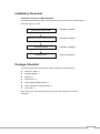
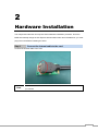
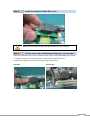
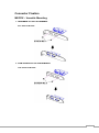
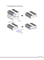
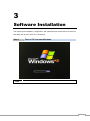
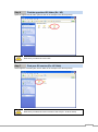
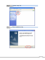
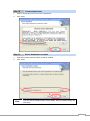
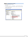
MEC-USB-M002 Mini PCI-e 2-port USB 3.0 board User’s Manual Third Edition, February 2014 © 2014 Cervoz Co., Ltd. All rights reserved. Reproduction without permission is prohibited Mini PCI-e USB Card User’s Manual The software described in this manual is furnished under a license agreement and may be used only in accordance with the terms of that agreement. Copyright Notice © 2014 Cervoz Co., Ltd. All rights reserved. Reproduction without permission is prohibited. Trademarks Cervoz is a registered trademark of Cervoz Co., Ltd. All other trademarks or registered marks in this manual belong to their respective manufacturers. Disclaimer Information in this document is subject to change without notice and does not represent a commitment on the part of Cervoz. Cervoz provides this document “as is,” without warranty of any kind, either expressed or implied, including, but not limited to, its particular purpose. Cervoz reserves the right to make improvements and/or changes to this manual, or to the products and/or the programs described in this manual, at any time. Information provided in this manual is intended to be accurate and reliable. However, Cervoz assumes no responsibility for its use, or for any infringements on the rights of third parties that may result from its use. This product might include unintentional technical or typographical errors. Changes are periodically made to the information herein to correct such errors, and these changes are incorporated into new editions of the publication. Technical Support Contact Information http://www.cervoz.com/support/technical.php Cervoz Co., Ltd. Tel: +886-2-2911-9599 Fax: +886-2-2911-9566 2 Table of Contents Introduction 4 Overviews 4 Features 4 Installation Flowchart 5 Package Checklist 5 Chapter 2 Hardware Installation 6 Chapter 3 Software Installation 13 Appendix Pin Assignments 20 Chapter 1 Board Side Pin Assignments 21 Device Side Pin Assignments 21 Technical Reference 22 MEC-USB-M002 Specifications 22 MEC-USB-M002 Dimensions 23 MEC-USB-M002 Daughter Board Dimensions 23 Product Warranty Statement 24 3 1 Introduction Overview MEC-USB-M002 is a USB 3.0 card for embedded PC. The card follows the Mini PCI-e standard which is complaint with PCI Express x 1 classification and small form factor (30.00 x 50.95 mm). This board fits in any host computer that has Mini PCI-e card slots. Features The PCI Express boards have the following outstanding features: Single-Lane (x1) PCI-Express with throughput up to 5.0/2.5Gbps Fully compliant with PCI-Express Base Specification Rev 2.0 Two USB3.0 Super-Speed ports Support simultaneous operation of multiple USB 1.1, USB 2.0, and USB 3.0 devices USB data transfer rate of 1.5/12/480/5000 Mbps Universal Serial Bus 3.0 specification Revision 1.0 compliant Support Hot-Swap function 4 Installation Flowchart Installation Flowchart of MEC-USB-M002 The following flowchart provides a brief summary of the procedure you should follow to install the Mini PCI-e card: Connect the internal cable Hardware Installation Install the card in the Mini PCI-e slot Hardware Installation Connector Fixation Hardware Installation Install the driver Software Installation Package Checklist The following items are included in the Mini PCI Express board Package: Mini PCI-e Card x 1 Daughter Board x 1 Bracket x 1 M2.5 Screw x 2 20Pin Internal Cable (30cm) x 1 Quick Installation Guide (Printed) x 1 Driver CD x 1 Note: Notify your sales representative if any of the above items are missing or damaged. 5 2 Hardware Installation This chapter describes the PCI Express Series hardware installation procedure. Since the BIOS automatically assign the PCI Express board’s IRQ number and I/O addresses, you must plug in the board before installing the driver. Step 1 Connect the internal cable to the card Connect the internal cable to the card Note Both sides of the cable connectors are the same, it doesn’t matter which side you connect 6 Step 2 Install the card to the Mini PCI-e slot Make sure you install the card in the right position (fool-proof design) Step 3 Fix the card on the motherboard (clip type or screw type) There are 2 options to fix the card. It depends on the design of the motherboard (clip or screw). 1. Clip type: make sure you press down the card and let the clips fix the card 2. Screw type: make sure you tighten up the screws to fix the card Clip type Screw type 7 Step 4 Card installation completed Clip type Screw type Step 5 Connect the cable to the daughter board Connect other side of the cable to the daughter board and connect the power cable to the daughter board Note Both sides of the cable connectors are the same, it doesn’t matter which side you connect 8 Connector Fixation MECFIX – Versatile Mounting 1. Standard PCI/PCIe Bracket PCI / PCIe IO Bracket 2. Low Profile PCI/PCIe Bracket Low Profile IO Bracket 9 3. Internal Mounting Upper Fixation – Industrial System Right & Left Fixation –Industrial System 10 4. Customized Front / Rear Plate Front / Rear I/O Plate Universal Bracket 11 3 Software Installation This chapter gives installation, configuration, and update/removal procedures for the driver for Win 2003, Win XP, Win Vista, Win 7, and Win 8. Step 1 Note Turn on PC and start Windows XP OS as example 12 Step 2 1. Windows automatically detects the new device If the card is installed properly, system would detect the new device and the hardware wizard would start automatically. 2. Click “Cancel” to disregard Step 3 Insert CD Open the CD drive 13 Step 4 Find the “MEC-USB-M002” folder Open the “MEC-USB-M002” folder Step 5 Find the “Driver” folder Open the “Driver” folder 14 Step 6 Find the appointed OS folder (Ex.: XP) Open the appointed OS folder (We use XP as an example in the above picture) Make sure you select the correct OS Step 7 Find your OS version (Ex.: XP 32bit) Select appoint OS folder (We use XP 32bit as an example in the above picture) Make sure you select the correct version of the OS (Ex.: 32-bit or 64-bit) 15 Step 8 Find the “setup” file Run the “set up” file Step 9 Driver installation set up Click “Next” 16 Step 10 License Agreement 1. Select “I accept the terms in the license agreement” 2. Click “Next” Step 11 Select destination location 1. Select the location where the driver would be installed 2. Click “Next” Note If you are not sure what location to be installed, keep the default setting and click “Next”. 17 Step 12 Start driver installation Click ”Install” Step 13 Driver installation completed Click “Finish” 18 Step 14 Confirm if driver is installed 1. Start “Computer Management” program 2. Go to the route: My Computer → Manage → Device Manager → Universal Serial Bus controllers 3. You would find the driver names: NEC Electronics USB 3.0 Host Controller and NEC Electronics USB 3.0 Root Hub 4. Device is ready to be used 19 Appendix Pin Assignments 20 Board Side Pin Assignments Power Input Connector Pin Header (CN21、CN22) Pin Description (PWR_IN7) Pin Description Pin Description 1 +5V 2 N/C 1 +5V 3 USB3_R1+ 4 +5V 2 GND 5 USB3_R1- 6 USB3_R2+ 3 GND 7 GND 8 USB3_R2- 4 N/C 9 USB3_T1+ 10 GND 11 USB3_T1- 12 USB3_T2+ 13 GND 14 USB3_T2- 15 USB2_T1+ 16 GND 17 USB2_T1- 18 USB2_T2+ 19 GND 20 USB2_T2- Device Side Pin Assignments USB3.0 Standard A Connector (USB1、USB2) USB1 Pin Description USB2 Pin Description 1 +5V 1 +5V 2 USB2_T1- 2 USB2_T2- 3 USB2_T1+ 3 USB2_T2+ 4 GND 4 GND 5 USB3_R1- 5 USB3_R2- 6 USB3_R1+ 6 USB3_R2+ 7 GND_DRAIN 7 GND_DRAIN 8 USB3_T1- 8 USB3_T2- 9 USB3_T1+ 9 USB3_T2+ 21 Technical Reference MEC-USB-M002 Specifications General PCI-Express Revision PCI-Express Electromechanical Revision Hardware Controllers Bus Interface (Connector) USB 3.0 PCI-Express Base Specification Rev 2.0 PCI-Express Mini Card Electromechanical Rev. 2.0 Renesas (NEC) μPD720200A Single-Lane (x1) PCI-Express with throughput up to 5.0/2.5Gbps 2 (USB) Performance Data Transfer rate of 1.5 / 12 / 480 / 5000 Mbps. Data Transfer Rate Driver Support Operating Systems Power Requirement Power Consumption Dimensions Width x Length (mm) Environmental Limits Operating Temperature Storage Temperature Humidity Regulatory Approvals EMC EMI EMS Reliability MTBF Warranty Low Speed (1.5Mbps), Full Speed(12Mbps), High Speed(480Mbps), Super Speed(5Gpbs) Win 2003, Win XP, Win Vista, Win 7, Win 8 [email protected] 30.00 x 50.95 -20°C ~ 70°C -20°C ~ 85°C 5% ~ 95% CE, FCC EN 55022, EN61000-3-2, EN61000-3-3, FCC Part 15 Subpart B Class B En 55024, IEC 61000-4-2, IEC 61000-4-3, IEC 61000-4-4, IEC 61000-4-5, IEC 61000-4-6, IEC 61000-4-8, IEC 61000-4-11 2,942,474 hr 3 years 22 MEC-USB-M002 Dimensions MEC-USB-M002 Daughter Board Dimensions 23 Product Warranty Statement Cervoz products are warranted to be free from manufacturing defects in materials and workmanship starting from the date of delivery. The actual warranty period of Cervoz products vary with product categories. Complete details can be found here: http://www.cervoz.com/support/warranty.php During the warranty period, we shall, at our option, either repair or replace any product that proves to be defective under normal operation. Defects, malfunctions, or failures of the warranted product caused by damage resulting from natural disasters (such as by lightening, flood, earthquake, etc.), environmental and atmospheric disturbances, other external forces such as power line disturbances, plugging the board in under power, or incorrect cabling, and damage caused by misuse, abuse, and unauthorized alteration or repair, and the product in question is either software, or an expendable item (such as a fuse, battery, etc.), are not warranted. RMA Instruction Customers must fill in Cervoz Return Merchandise Authorization (RMA) Request Form and obtain a RMA number prior to returning a defective product to Cervoz for service. Customers must collect all the information about the problems encountered and note anything abnormal and describe the problems on the “Cervoz Service Form” for the RMA number application process. Charges may be incurred for certain repairs. Cervoz will charge for repairs to products whose warranty period has expired. Cervoz will also charge for repairs to products if the damage resulted from acts of God, environmental or atmospheric disturbances, or other external forces through misuse, abuse, or unauthorized alteration or repair. If charges will be incurred for a repair, Cervoz lists all charges, and will wait for customer’s approval before performing the repair. Customers agree to insure the product or assume the risk of loss or damage during transit, to prepay shipping charges, and to use the original shipping container or equivalent. Customers can send back faulty products with or without accessories (manuals, cable, etc.) and any components from the card. If the components were suspected as part of the problems, please note clearly. Otherwise, Cervoz is not responsible for the devices/parts. Repaired items will be shipped along with a "Repair Report" detailing the findings and actions taken. Limitation of Liability Cervoz’ liability arising out of the manufacture, sale, or supplying of the product and its use, whether based on warranty, contract, negligence, product liability, or otherwise, shall not exceed the original selling price of the product. The remedies provided herein are the customer’s sole and exclusive remedies. In no event shall Cervoz be liable for direct, indirect, special or consequential damages whether based on contract of any other legal theory. 24