1
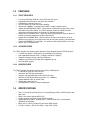
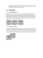
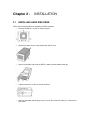
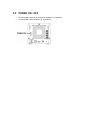
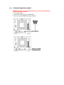
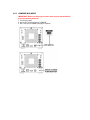
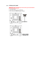
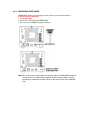
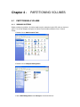
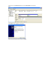
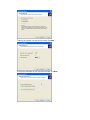
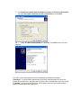
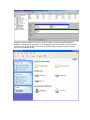
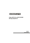
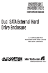
TOWERRAID TR2UT-B
DETAILED USER’S MANUAL v1.0
Table of Content
Chapter 1 - WELCOME.................................................................................................. 4
1.1
INTRODUCTION............................................................................................................................. 4
1.2
PRECAUTION ................................................................................................................................. 4
1.3 FEATURES ...................................................................................................................................... 5
1.3.1
TR2UT FEATURES ................................................................................................................. 5
1.3.2
SATA FEATURES ................................................................................................................... 5
1.3.3
USB FEATURES...................................................................................................................... 5
1.4
SPECIFICATIONS ........................................................................................................................... 5
1.5 RAID MODE .................................................................................................................................... 6
1.5.1
Disk Striping (RAID 0)............................................................................................................ 6
1.5.1
Disk Mirroring (RAID 1) .......................................................................................................... 6
1.5.2
Concatenation (Spanning)......................................................................................................... 7
1.5.3
Contiguous (JBOD/Single Drive/Segment) .............................................................................. 7
1.6 SYSTEM REQUIREMENTS ............................................................................................................. 7
1.6.1
PC SYSTEMS........................................................................................................................... 7
1.6.2
MACINTOSH SYSTEMS ........................................................................................................ 7
1.7
PRODUCT CONTENTS................................................................................................................... 7
Chapter 2 - INSTALLATION......................................................................................... 9
2.1
INSTALLING HARD DISK DRIVE.................................................................................................. 9
2.2
POWER ON / OFF......................................................................................................................... 10
Chapter 3 - CONFIGURATION................................................................................... 11
3.1 CONFIGURATION PREREQUISITES.......................................................................................... 11
3.1.1
SATA HOST CONNECTIONS.............................................................................................. 11
3.1.2
USB HOST CONNECTIONS ................................................................................................ 11
3.2
CHANGING HOST CONNECTIONS ............................................................................................ 11
3.3 DISCONNECTING A USB DEVICE.............................................................................................. 11
3.3.1
WINDOWS SYSTEMS.......................................................................................................... 11
3.3.2
MACINTOSH SYSTEMS ...................................................................................................... 12
3.4
HARD DISK DRIVE HOT-PLUG & UNPLUG ............................................................................. 12
3.5 LED INDICATIVE STATUS........................................................................................................... 12
3.5.1
POWER LED.......................................................................................................................... 12
3.5.2
eSATA HOST LED ................................................................................................................ 12
3.5.3
USB HOST LED..................................................................................................................... 13
3.5.4
SYSTEM ALARM LED......................................................................................................... 13
3.5.5
HDD LEDs.............................................................................................................................. 13
3.6 MODE SETTING ........................................................................................................................... 13
3.6.1
STANDARD (INDIVIDUAL) MODE................................................................................... 14
3.6.2
COMBINE (BIG) MODE ....................................................................................................... 15
3.6.3
STRIPING (FAST) MODE..................................................................................................... 16
3.6.4
MIRRORING (SAFE) MODE................................................................................................ 17
Chapter 4 - PARTITIONING VOLUMES .................................................................. 18
4.1 PARTITIONING A VOLUME ........................................................................................................ 18
4.1.1
WINDOWS SYSTEMS.......................................................................................................... 18
4.1.2
MACINTOSH SYSTEMS ...................................................................................................... 23
Chapter 5 - FAQ ............................................................................................................. 28
Chapter 1 1.1
WELCOME
INTRODUCTION
Thank you for choosing TOWERRAID TR2UT TR2UT. It is a ideal solution for digital home and
small office TR2UTs. Features of the TOWERRAID TR2UT include advanced RAID modes,
trayless design, ventilating protective cover and USB/eSATA dual interface. There are four
different configurations RAID mode (Standard, Combine, Striping, and Mirroring), each offering a
different subset of features and capabilities.
The Storage Processors are powered by Silicon Image’s industry-leading SteelVine™
architecture which provides:
•
•
•
•
•
•
•
1.2
SATA or USB host connectivity
eSATA capable on SATA ports
Enhanced data protection
High-performance storage
Plug-and-play functionality
Automatic disk rebuild (when MIRRORING volume is configured)
Support latest 1TB hard drive, with up to 2TB total storage capacity
PRECAUTION
Please read the safe precautions carefully before you using TOWERRAID TR2UT. Ensure that
you use the product correctly according to the procedure described in this guide. The following
safety precautions are intended to remind you to operate the product safely and correctly. Please
read and ensure that you understand them before you proceed to the other sections of this guide.
• Do not attempt to disassemble or alter any part of the product that is not describe in this
guide.
• Do not allow the product to come into contact with water or other liquids. In the event that
water or other liquids enter the interior, immediately unplug the product from the
computer. Continued use of the product may result in fire or electrical shock. Please
consult your product distributor or the closest support center.
• Do not handle the product near a heat source or expose them to direct flame or heat.
• Never place the product in close to equipment generating storage electromagnetic fields.
Exposure to strong magnetic fields may cause malfunctions or corrupt data.
• Model does not support Windows 3.x/ 95 / 98SE/ ME/ NT.
• Hard disk drive is not including.
• Please be noted the following product may run irregularly which are not under warranty.
o Toshiba DynaBook, Satellite series (All K6 CPU models).
o IBM Aptiva E series (All K6 CPU models).
o Sotec E-note M260 series.
o All AMD K6 system.
o PC with sis7000/ 7001/ 7002 PCI to USB host controller.
1.3
FEATURES
1.3.1
TR2UT FEATURES
•
•
•
•
•
•
•
•
•
1.3.2
1 host port (eSATA or USB) to 2 Serial ATA hard disk drives.
Compatible with SATA Gen1 and Gen2 host controllers.
Embedded fast Storage Processor.
Ultra-fast 3Gbps host and device port capability.
Greater than 100MBps sustained reads in RAID 1 mode (limited by drives).
Support Disk MIRRORING (SAFE) - allows device to automatically copy primary hard
drive without any CPU loading. The TR2UT provides automatic rebuild on device
replacement and auto-failover, to eliminate any workflow interruptions.
Support Disk STRIPING (FAST) - allows the device to performance stripe the drives to
provide maximum throughput to the direct attached PC.
Support Disk COMBINE (BIG) - allows the device to make any two drives (same or
different sizes) appear as one large drive to the host for extra capacity (Concatenation).
Support STANDARD Disk (Individual) - this allows the direct attached PC to see each
drive as just an individual drive.
SATA FEATURES
The TR2UT provides the following Serial Advanced Technology Attachment (SATA) features:
• 1 eSATA host port to 2 SATA devices (Port Multiplier Functionality).
• Auto-negotiation between SATA I (1.5Gpbs) and SATA II (3Gpbs).
• Supports hot plug and Plug-and-play functionality
• Supports host control of hard disk drive staggered spin-up.
• Host side NCQ support.
1.3.3
USB FEATURES
The TR2UT provides the following Universal Serial Bus (USB) features:
• 1 USB 2.0 host port to 2 SATA devices.
• Compliant with USB 2.0 specifications.
• Supports and compatible with OHCI/UHCI/EHCI hosts.
• Operates at USB full and High-speed rates (12 ~ 480Mb/s).
• Support Multiple LUNs (up to four LUN).
• Support Mass Storage Class.
• OS independent, Driverless, Auto Configuration.
1.4
•
•
•
•
•
•
SPECIFICATIONS
Two 3.5-inch SATA hard disk drives to a standard B type USB or eSATA interface with
door cover.
Power, Host, Alerm and two HDD LEDs.
Design based on the Silicon Image Sii5744 controller.
Support Mirroring (SAFE), Striping (FAST), Combine (BIG Drive), and Standard
(Individual Drive) modes.
Metal chassis (SECC) and plastic panel frame (ABS) design.
135 (W) x 120 (H) x 255 (D) mm, NW: 1.2 Kgs, GW: 1.5Kgs..
•
•
60 watts switching power, 90 to 264Vac / 47~63Hz with CE/ FCC/ UL/ C-UL/ TUV/ CB/
BSMI/ PSE requirement. Physical Dimensions: 108 mm (L) x 65 mm (W) x 31 mm (H).
Single packing (color box) and 8 in 1 outer carton.
1.5 RAID MODE
1.5.1
Disk Striping (RAID 0)
Striping is a performance-oriented, non-redundant data mapping technique. While Striping is discussed as
a RAID Group type, it is does not provide any fault tolerance. With modern SATA and ATA bus
mastering technology, multiple I/O operations can be performed in parallel, enhancing data throughput.
Striping arrays use multiple disks to form a larger virtual disk. The figure below illustrates a three-disk
stripe set. Stripe one is written to disk one, stripe two to disk two, and so forth. RAID 0 sets can be
comprised of two, three, or four drives. If the sizes of the disk segments are different, the smallest disk
segment will limit the overall size of the RAID Group.
Stripe0
Stripe1
Stripe2
Stripe3
Stripe4
Stripe5
Stripe6
Stripe7
Stripe8
Stripe9
Stripe10
Stripe11
1.5.1
Disk Mirroring (RAID 1)
Disk mirroring creates an identical twin for a selected disk by having the data simultaneously written to
two disks. This redundancy provides instantaneous protection from a single disk failure. If a read failure
occurs on one drive, the system reads the data from the other drive. RAID 1 sets are comprised of two
drives, and a third drive can be allocated as a spare in case one of the drives in the set fails. If the sizes of
the disk segments are different, the smallest disk segment will limit the overall size of the RAID Group.
Block 0
Block 1
Block 0
Block 2
Block 1
Block 3
Block 2
Block 3
1.5.2
Concatenation (Spanning)
The Concatenated mode combines multiple disks or segments of disks into a single large volume. It does
not provide any data protection or performance improvement but can be useful for utilizing leftover
space on disks. Concatenation allows the segments that make up the volume to be of different sizes.
1.5.3
Contiguous (JBOD/Single Drive/Segment)
The single drive is a virtual disk that can either be an entire disk drive or a segment of a single disk drive.
Single drive is the “Contiguous” configuration option when creating RAID Groups (or sets) in the
SATARAID5 software.
1.6 SYSTEM REQUIREMENTS
1.6.1
•
•
•
•
•
•
•
•
•
1.6.2
•
•
•
•
•
•
PC SYSTEMS
Intel Pentium-III 500MHz equivalent or faster
Windows 2000, XP, 2003 Server or Windows Vista with the latest Service Packs
CD-ROM drive
64 MB of RAM (minimum)
250 MB of free disk space
Super VGA (800 x 600) or higher resolution display with at least 256 colors
Mouse or compatible pointing device
SATA connection: Host Bus Adapter card (controller number Sii3124 or Sii3132) and
associated software drivers with Port Multiplier support
USB connection: USB 1.0 or 2.0 direct host connection or USB hub
MACINTOSH SYSTEMS
PowerMac G5, MacBook Pro or Mac Pro
MacOS X, 10.4.8 (or later)
CD-ROM drive
Mouse or compatible pointing device
SATA connection: Host Bus Adapter card (controller number Sii3124 or Sii3132) and
associated software drivers with Port Multiplier support
USB connection: USB 1.0 or 2.0 direct host connection or USB hub
1.7 PRODUCT CONTENTS
The following parts are content.
•
•
•
•
•
•
•
Setup and Installation Driver Repository CD x 1
USB 2.0 Cable x 1.
eSATA Cable x 1
TR2UT x 1.
Power Adapter x 1.
Power Cable x 1.
Tool-less Screw x 1
Chapter 2 2.1
INSTALLATION
INSTALLING HARD DISK DRIVE
Please refer below procedure to complete the HDD installation.
• Unfasten the tool-less screws on the back panel.
•
Remove the upper chassis cover backwards and lifts it up.
•
Open the front door and install the HDDs in order from the bottom to the top.
•
Tighten the tool-less screws to secure the drives.
•
Close the front door and the upper chassis cover, than fasten the Tool-less screws on the
back panel.
2.2 POWER ON / OFF
•
•
Push the power switch on the back panel to position “I” to power on.
Push the power switch to position “O” to power off.
Chapter 3 -
CONFIGURATION
3.1 CONFIGURATION PREREQUISITES
3.1.1
SATA HOST CONNECTIONS
This guide assumes that you have already attached the TR2UT to a host computer that
has been installed with the Sii3124 or Sii3132 HBA (Host Bridge Adapter) or another third
party SATA HBA with Port Multiplier (PM) support.
If you use a host controller that does not provide Port Multiplier support, the JBOD RAID
mode is unavailable when configuring the TR2UT. Only one disk is available on the host
computer.
3.1.2
USB HOST CONNECTIONS
If you are connecting your TR2UT using a USB connection to your host, the USB port
should be compliant with USB 1.0, 2.0 or connected to a USB hub.
3.2 CHANGING HOST CONNECTIONS
The TR2UT supports both USB and eSATA host connections, although only one connection can
be attached at any given time. For the best data transfer performance, you should always use the
eSATA host connection.
If it becomes necessary to change the host connection between eSATA and USB, the host
computer system and the TR2UT should both be powered down prior to making the host
connection change to avoid any potential data loss or corruption. After changing the host
connection, all items can be powered-up to resume operation with the new host connection.
3.3 DISCONNECTING A USB DEVICE
USB 2.0 external devices provide support for “plug & play” connection, so that your USB storage
device can be connected and disconnected while the computer is running. To prevent data loss
or other failures, you must follow these steps when disconnecting your USB 2.0 storage device
from your host computer system. Once the physical USB device is disconnected, any volumes
that are associated with that device will become unavailable. On O/S (Operation Systems), the
TR2UT must be stopped from O/S before any devices can be disconnected.
3.3.1
WINDOWS SYSTEMS
1. Click on the Eject icon (a small green arrow over a hardware image) in the System
Tray located in the lower right-hand side of your screen.
2. A message will appear listing all of the devices that the Eject icon controls. Click on the
“Safely remove USB Mass Storage Device” item.
3. The following message then appears: “Safe to Remove Hardware”. You can now safely
disconnect the device from your computer.
Note: If your host USB adapter does not support this feature, the device should be
disabled using the Device Manager or your system should be shut down cleanly
and powered off before disconnecting the USB device.
3.3.2
MACINTOSH SYSTEMS
You must un-mount the hard drive system by dragging the hard drive icon to the trash before
disconnecting it or powering it down.
3.4
HARD DISK DRIVE HOT-PLUG & UNPLUG
When using a SATA host connection, the hard disk drives can be hot-plugged or hot-unplugged
while the system is running. However, to avoid data corruption or loss, care should be taken to
ensure that the host system is not currently using any drive that is about to be hot-unplugged.
When using a USB host connection, the hard disk drives should not be hot-plugged or hotunplugged while the system is running. Instead, you should eject the drives or shut down your
host system before connecting or disconnecting any hard disk drives.
3.5 LED INDICATIVE STATUS
TR2UT provides information on the SATA HDDs, System Alarm, USB Host, eSATA Host, and
Power LEDs.
Each LED activity will turn On/Off the LED for approximately 70 ms. The blinking rate is
approximately 400 ms On and 400 ms Off.
3.5.1
POWER LED
The TR2UT has one Green color Power LED. The table shows Power LED function and
operation.
DESCRIPTION
Power On
Power Off
3.5.2
GREEN LED
On
Off
eSATA HOST LED
The TR2UT has one Green color eSATA Host LED. The table shows eSATA Host LED function
and operation.
DESCRIPTION
eSATA Host Unplugged / No
Power
eSATA Host Unplugged (Idle)
eSATA Host Unplugged (Active)
GREEN LED
Off
On
On
3.5.3
USB HOST LED
The TR2UT has one Green color USB Host LED. These LEDs behave as follows:
DESCRIPTION
USB Host Unplugged / No Power
USB Host Unplugged (Idle)
USB Host Unplugged (Active)
3.5.4
GREEN LED
Off
On
On
SYSTEM ALARM LED
The TR2UT has one Red color System Alarm LED. These LEDs behave as follows:
DESCRIPTION
Normal State
Error State (One or More Bad
Partial Volumes on Mirroring
Mode only)
3.5.5
RED LED
Off
On
HDD LEDs
The TR2UT has two HDD LEDs (Green and Red). The table shows HDD LED function and
operation. These LEDs behave as follows:
DESCRIPTION
HDD Unplugged / No Power /
HDD plugged (Idle)
GREEN LED
Off
On
RED LED
Off
Off
HDD plugged (Active)
On
Blink (On)
HDD Rebuild (A Physical Partition
is being Rebuild; i.e. Mirroring
Mode)
On
Blink (On)
Will appear
as On
Error State (One or More Bad
Partial Volumes)
Off
Off
3.6 MODE SETTING
The TR2UT with the device’s LEDs to indicate status. To select a RAID mode in this mode the
first time that a new factory-shipped product is used, ensure that the hard disk drives are installed;
turn on the power before set the DIP switch on the back of the TR2UT to the desired RAID mode.
To change the RAID mode thereafter, set the DIP switch to the desired position and press the
recessed Mode Change push-button to create the new virtual volume(s). Creating new virtual
volumes will destroy any existing data that existed on the previous volume, but expanding an
existing COMBINE (BIG) volume will not destroy any existing data.
3.6.1
STANDARD (INDIVIDUAL) MODE
IMPORTANT: Before reconfiguring a volume, back up your data and delete
previously defined partitions.
1. Turn on the power.
2. Set the DIP switch position to STANDARD.
3. Press the recessed Mode Change push-button.
3.6.2
COMBINE (BIG) MODE
IMPORTANT: Before reconfiguring a volume, back up your data and delete
previously defined partitions.
1. Turn on the power.
2. Set the DIP switch position to COMBINE.
3. Press the recessed Mode Change push-button.
3.6.3
STRIPING (FAST) MODE
IMPORTANT: Before reconfiguring a volume, back up your data and delete
previously defined partitions.
1. Turn on the power.
2. Set the DIP switch position to STRIPING.
3. Press the recessed Mode Change push-button.
3.6.4
MIRRORING (SAFE) MODE
IMPORTANT: Before reconfiguring a volume, back up your data and delete
previously defined partitions.
1. Turn on the power.
2. Set the DIP switch position to MIRRORING.
3. Press the recessed Mode Change push-button.
Note: After you have pressed the Mode Change push-button, the MIRRORING mode will
start to rebuild. (The rebuilding time depends on the capacity of HDD.) Once the
rebuilding has completed, the HDD indicative LEDs will turn RED then to GREEN
color.
Chapter 4 -
PARTITIONING VOLUMES
4.1
PARTITIONING A VOLUME
4.1.1
WINDOWS SYSTEMS
Before creating any partitions, disk drive mode must be selected using the DIP switch on the back
panel. Turn on the computer and open the Control Panel window (located at: Start > Control
Panel).
1. Double-click on Administrative Tools.
2. Double-click on Computer Management.
3. Select Disk Management under Storage to view the disk drives.
4. Right-click on each Unallocated partition and select New Partition from the pop-up
menu.
5. Click Next to create a partition on a basic disk.
6. Select the partition type you want to create, click Next.
7. Specify the partition size you want to create, click Next.
8. Assign the drive letter or path you want to create, click Next.
9. Click Format this partition with the following settings and Perform a quick format,
select the File system, Allocation unit size, Volume label, and click Next.
10.
When the New Partition Wizard has completed, click Finish, and restart your
computer.
The status of the created partition in the Disk Management window will change to
“Formatting”. The percentage complete will be displayed. Depending upon the size of the
partition, the format process may take several minutes. When completed, the status will change
to “Healthy” and the name and drive letter will be updated. Once the disk reports Healthy, it
appears to the computer and ready to use.
Repeat the above procedure if there are any other partitions. Close the Data Management
window by clicking on the small boxed “X” in the top right corner of the window. Click on the “My
Computer” icon on the Desktop. The new drives will be display and properly named. The new
disks are now available for use.
4.1.2
MACINTOSH SYSTEMS
Click Go, click on Utilities.
2.
Double-click Disk Utility.
3.
In the windows on the left, Select the newly added Storage
4.
In the windows on the right, click Partition to go to partition window.
5.
Select Volumes Scheme.
6.
Enter Volumes Information, such as “Name” and “Format” click Partition.
7.
Confirm to partition the disk by click Partition.
8.
The newly formatted disk with the Volume name will display on the windows in the left.
9.
Repeat the above procedure as needed for any other disks.
10. Close the Disk Utility window upon completion.
11. The new disks will appear on the desktop and ready for use..
Chapter 5 -
FAQ
If you need some help for troubleshooting, please check the frequently asked question below, it
may help you problem solved quickly
•
Can not recognize
Make sure all cables have been connected properly.
•
Can not operate in O/S
Make sure the O/S is support for the product.
•
Transmission speed is slow
If connect USB1.1 interface, the speed will be around 1MB/sec only.
•
When format in the Windows 2000/ XP/ Vista/ Server 2003, the dialog box appear
“Unfinished formatting”
Windows 2000/ XP/ Vista/ Server 2003 can not format HDD over 32GB by FAT32,
Please format by NTFS.
•
When using different capacity or brand HDD, can we still using COMBINE mode?
Yes
•
When system is damaging on COMBINE mode, is it possible to keep the data?
No. The system is different with RAID. That’s because the filed of HDD data combine, It
may be read from disk has the data in the front. The “Sample 1” image below, it takes out
only disk 2, and it may read the data from disk 1. The “Sample 2” image below, the entire
disk can not be read.