1
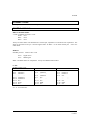
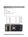
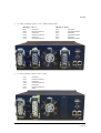
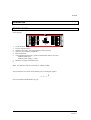
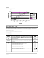
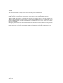
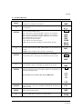
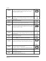
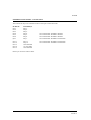
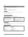
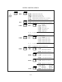
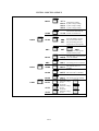
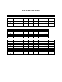
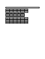
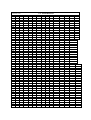
TOTEM www.dimmer.de DIGITAL DIMMERS, PROFESSIONAL LINE 12Ch x 3Kw / 6Ch x 6Kw / 3Ch x 12Kw USER MANUAL Version 1.5 TOTEM INDEX INDEX................................................................................................................................................................. 1 TOTEM, DIMMER PACK ................................................................................................................................ 3 TECHNICAL CHARACTERISTICS ............................................................................................................... 5 PROTECTIONS.............................................................................................................................................. 6 CONNECTIONS................................................................................................................................................. 7 CONTROL SIGNALS ................................................................................................................................... 7 POWER INPUT & OUTPUTS...................................................................................................................... 8 OPERATION ....................................................................................................................................................11 FRONTAL PANEL ......................................................................................................................................11 MANUAL TEST of the OUTPUT CHANNELS - MAN..........................................................................12 DMX DIRECTION - DIR...........................................................................................................................13 CURVE SELECTION - CURV..................................................................................................................14 RESPONSE TIMES - TIME.......................................................................................................................16 TEST MENU ................................................................................................................................................17 BACKUP FUNCTION - BACK...............................................................................................................18 MIDI CONFIGURATION - MIDI............................................................................................................20 FEEDBACK CONTROL BY INPUT PHASE (OPTION).......................................................................23 ARCHITECTURAL AND ORNAMENTAL LIGHTING – A.L.............................................................25 EXAMPLES FOR MD1: ARCHITECTURAL LIGHTING.................................................................27 EXAMPLES FOR MD2: ORNAMENTAL LIGHTING. .....................................................................27 EXAMPLES FOR MD3: MUSEUM LIGHTING. ................................................................................27 A.L. CONFIGURATION.........................................................................................................................29 EXTERNAL KEYS PANEL - CONNECTION.....................................................................................31 PREHEAT FUNCTION - PRHT.................................................................................................................32 DIMMER CHANNELS PATCH - PTCH...................................................................................................32 SAVING THE DIMMER PROGRAM: SHOW.........................................................................................33 SYSTEM COLD RESET .............................................................................................................................34 INSTALLATION..............................................................................................................................................35 MAINTENANCE AND TECHNICAL SERVICE ........................................................................................36 LT & 1 TOTEM 2 & LT TOTEM TOTEM, DIMMER PACK Digital dimmer of professional line, with high performance and quality of regulation, completely digital and very competitive in the actual market. The TOTEM dimmers belong a dimmers line with a new concept of design. These dimmers are designed for fixed installation or/and to use them in tours. Installed them in 19” standard racks or working independently. It is the perfect dimmer for Theatres, Auditoriums, Discotheques, TV Studies and other events. The TOTEM dimmer park is designed to obtain a precise regulation and without problems. Internal functions like: Auto-adjust with the input frequency. Zero crosses controlled by the microprocessor. Rearm slowly in the switch on… Permit to the TOTEM dimmer works in the more hard conditions, with electric generators, or in noise conditions. The dimmer is capable to detect and isolate the input noise, avoiding blink in its outputs and absorbing the frequency variations. LT & 3 TOTEM There are three types of TOTEM dimmer: TOTEM of 12CH x 3KW TOTEM of 6CH x 6KW. TOTEM of 3CH x 12KW. 4 & LT TOTEM TECHNICAL CHARACTERISTICS • • • • • • • • • • • • • • • • • • • • • • • • • Channels / Power: 12 channels x 3 kW 6 channels x 6 kW 3 channels x 12 kW Rearm slowly in the switch on (≈ 2 s). Automatic adjustment with the main input frequency: 40Hz - 70Hz. Zero crosses are generated by the microprocessor, in perfect synchronisation with the each input phase. This process permit us detect and isolate the possible input noise. Backup function: maintains the last DMX signal or actives one backup preset, when the DMX signal is missing or fault the communication. 3 input phases. Power supply: R+S+T+N+T (180V-280V~ / 40Hz -70Hz). 36 kW. Basic. The control electronic is supplied from the R phase. Advanced. The control electronic is supplied from the R, S and T phase. The CPU works when 1 or 2 of these phases fault. Voltmeter by phases and input close loop. Protection fuse by phase: 3x T500mA/250V. Protection by channel dimmer: 2 pole circuit breaker, DPN, to protect the phase and to section the neutral (optionally, it is possible have 1 pole circuit breaker by channel). Forced ventilation. AMECON interference suppresser coils, with lineal response between the 25% and the 100% of the load, with a raise minimum time of 305 µs. Power devices: 25 A triac, by 3000 W channel. 40 A triac (or thiristor pack), by 6000 W and thiristor pack by 12.000 W. DMX-512 (1990) input control signal. MIDI-IN input control signal. 0 +10V input control signal. Manual test of channels. Modes: On/Off, Switch, Dimmer, and simulation of A.L. function). There are one key for each dimmer channel. Out witness Led by each channel. DMX input witness Led. Power supply witness Led (for internal circuits). Alphanumeric display: 4 high effectiveness digits, for general information and menus. 3 function keys to use the menus. 5 regulation curves: Lineal, square, invert square, on/off & park. These curves are self-adjustment with the input frequency. Menus: Selection of the assigned function to the channel manuals keys. Selection of the DMX direction. Selection of the response curve, in generic mode or by channel. Selection of the response times, in generic mode or by channel. TEST functions for: DMX, MIDI, 0+10V, Outs, User and others. Backup presets: to store presets and parameters set-up. Configuration of the MIDI port (channel, note & mode). A.L. function (for architectural or ornamental lighting). Preheat function. Set up of input closed loop. Fault Test of over-voltages, over-temperature and other... No lineal patch. Main power input: 5 connection borne, for 4 mm section cables or Harting 4 poles + Ground (80 A). Power output: Harting connector. LT & 5 TOTEM • • Size: 4U x 19" 22 Kg. Paint in blue. Control Unit: Microprocessor H8/3003 / 16 bits / 16MHz. Program memory: 128 KB Data memory: 8 KB Electric Characteristics: • Main power input: 3 phases + neutral + earth 230V~ / 12 kW - 50/60Hz. (1 phase). 230/400V3~ /36 kW - 50/60Hz. (3 phases). • Protection by input phase: 3 x T fuses (slowly response) 0,5A. • Ambient conditions: Ambient temperature: -10ºC a 35ºC. Relative humidity, without condensation: 80%. • Installation category: CAT II. PROTECTIONS Main Power Input: 3 fuses, in the rear panel, 1 by phase. The valour fuses: 500 mA/250V type T (slowly response). Channels: 3Kw channels: circuit breaker, to protect the phase and to section the neutral. 6Kw and 12Kw: Two poles Circuit breaker, to protect the phase and neutral. 6 & LT TOTEM CONNECTIONS All are placed in the rear of the dimmer pack. CONTROL SIGNALS DMX-IN & DMX-THRU. 2 XLR-5 standard connectors. Code: GND Pin 1 Data - Pin 2 Data + Pin 3 Always use data cables with shielded and 1 twisted pair, impedance of 120 Ω and low capacitance. The shield is connected to the pin 1 and the signals Data - & Data + in the same twisted pair. Never use audio cables. MIDI-IN. Standard protocol. 1 DIN-5 180º. Code: Pin 4 Pin 5 Signal return MIDI signal Nota: All MIDI cables are compatibles. Always use MIDI standard cables. 0 +10V. SUBD-15 male. Code: TOTEM 12 channels Pin 1 Channel 1 Pin 2 Channel 2 Pin 3 Channel 3 … … … Pin 11 Channel 11 Pin 12 Channel 12 Pin 13 N.C. Pin 14 GND. Pin 15 N.C. Pin 1 Pin 2 … Pin 6 Pin 7 … Pin 13 Pin 14 Pin 15 TOTEM 6 channels Channel 1 Channel 2 … … Channel 6 N.C. … … N.C. GND. N.C. Pin 1 Pin 2 Pin 3 Pin 4 … … Pin 13 Pin 14 Pin 15 TOTEM 3 channels Channel 1 Channel 2 Channel 3 N.C. … … … … N.C. GND. N.C. N.C. is "no connected". LT & 7 TOTEM POWER INPUT & OUTPUTS Main Input Harting connector, 4 poles + Earth terminal (80 A): Code: Pin 1 Phase R Pin 2 Phase S Pin 3 Neutral Pin 4 Phase T Earth terminal.- Earth, For high powers, 600/800V with isolation C (VDE 0110) for 80 A. Earth terminal: VDE 0627. ¡Always connect the earth to the dimmer pack! Power output. • 12 x 3KW.- Harting: 24 poles + earth terminal, 16 A. (Optional: 2 Harting in parallel). Code: Pin 1 Pin 2 Pin 3 Pin 4 Pin 5 Pin 6 Pin 7 Pin 8 Pin 9 Pin 10 Pin 11 Pin 12 8 & LT Channel 1 Channel 2 Channel 3 Channel 4 Channel 5 Channel 6 Channel 7 Channel 8 Channel 9 Channel 10 Channel 11 Channel 12 Pin 13 Pin 14 Pin 15 Pin 16 Pin 17 Pin 18 Pin 19 Pin 20 Pin 21 Pin 22 Pin 23 Pin 24 Channel Neutral 1 Channel Neutral 2 Channel Neutral 3 Channel Neutral 4 Channel Neutral 5 Channel Neutral 6 Channel Neutral 7 Channel Neutral 8 Channel Neutral 9 Channel Neutral 10 Channel Neutral 11 Channel Neutral 12 TOTEM • 6 x 6 Kw. 2 Harting: 6 poles / 35 A + Earth terminal. Code: Harting 1 - OUT 1 Pin 1 Channel 1 Pin 2 Channel Neutral 1 Pin 3 Channel 2 Pin 4 Channel Neutral 2 Pin 5 Channel 3 Pin 6 Channel Neutral 3 • Harting 2 - OUT 2 Pin 1 Channel 4 Pin 2 Channel Neutral 4 Pin 3 Channel 5 Pin 4 Channel Neutral 5 Pin 5 Channel 6 Pin 6 Channel Neutral 6 3 x 12 Kw. Harting: 7 poles / 100 A. Code: Pin 1 Pin 2 Pin 3 Pin 4 Pin 5 Pin 6 Pin 7 Channel 1 Channel Neutral 1 Channel 2 Channel Neutral 2 Channel 3 Channel Neutral 3 Earth. LT & 9 TOTEM ! In the power output borne there are 230V~. 3kW dimmers: Maximum load.- 3kW (3 phases) or 1kW (1 phase) 6kW dimmers: Maximum load.- 6kW (3 phases) or 2kW (1 phase) 12kW dimmers: Maximum load.- 12kW (3 phases) or 4kW (1 phase) To connect alone appliances that without accessible parts with tension and whose hi-fidelity possess double isolation or reinforced with respect to the main power input. 10 & LT TOTEM OPERATION FRONTAL PANEL In the drawing: 1 6 3 2 1. 2. 3. 4. 5. 6. 7. 8. 4 7 5 TOTEM Circuit breakers. Frontal ventilation holes. Manual control keys, with output witness LED by channel. 3 function keys: MENU, ENTER & ↑. Reset pushbutton. 4 digit alphanumeric display, (general information & menus), near this: LED for DMX input. LED for power-supply (+5Vdc). Handles to transport the dimmer pack. Note: This manual is based in TOTEM: 12 channels x 3KW. The first time that we switch on the dimmer pack, in the display appears: _ _ _ 1 See too SYSTEM COLD RESET (Pg. 34) LT & 11 TOTEM MANUAL TEST of the OUTPUT CHANNELS - MAN From the frontal keys of your TOTEM you can control the dimmer channels, by default, these keys work like channel Flash. In the MAN menu, you can select the functionality for these keys. The output of the manual control is added to the output controlled by the DMX, MIDI or 0+10V signals. With these keys you can test the dimmer outputs, set-up a “scene” or simulate the external keys for A.L. function. Select the operation of these keys in the MAN menu: Key Function MENU Access to the dimmer menus. The first menu appears in the display ENTER Access to the MAN menu. The current option appears in the display (FLSH), marked with an asterisk, * ↑ Permit us to see the options of the MAN menu: FLSH (Flash) SWCH (Switch). DIMM (Dimmer). A.L. (Architectural or ornamental lighting- simulation) NONE (Keys with any function). ENTER Place in the display the desired function, for example SWCH. To select the showed potion like active option (marked with the asterisk). MENU Returns to the MAN menu. The second time, returns to the main display (---1). In Display... MAN FLS* FLSH SWCH DIMM A.L. NONE SWC* MAN Option FLSH: Option by default. When you press and hold down one key, its channel outs to the 100% in stage. When you free the key the channel outs to the 0%. Option SWCH: When you press one key, if its channel is at 0% switches to 100%, if its channel is at 100% switches to 0%. Like a switcher. Option DIM: Permits us to fade the channel. If you press and hold down the key one time, its channel begins a fade up in stage, up to 100% or until the key is free. In the display you can see the current level. If the key is pressed 2 times (double click), and hold down pressed, its channel begins a fade down in stage, up to 0% or until the key is free. Option A.L.: Architectural or ornamental lighting simulation. In this case the frontal keys work like the external keys for A.L. function. (See - page 25) Option NONE: The frontal keys have not function. Very used when the dimmer is in places with free access the people. 12 & LT TOTEM DMX DIRECTION - DIR The DIR menu permits us set-up the DMX direction, like the first DMX direction to receive by the Dimmer. The dimmer responds to 12 consecutive DMX directions. The DMX direction can be between 1 and 1024. 1 DMX line only has 512 channels. The DMX direction 513 is equal to the 1. Example: The TOTEM has to answer to the DMX channels 13-24. For this, select the DMX direction 13: MENU Access to the dimmer menus. The first menu is showed in the display Up to place in the display the desired option DIR. ↑ Remember, the desired direction for this example is 0 0 1 3 ENTER ENTER ENTER ENTER ó MENU Access to the selected menu. Now the number blinking can be edited with ↑ . In the example this digit does not need edition. Accept the previous digit, and now the next digit is blinking. Now the digit blinking can be edited. Press ↑ one time, to edit this digit as 1. Accept the previous digit, and now the last digit is blinking. 2 times (to edit this digit as 3) To accept the edited direction and exit to the DIR menu. Ó Press MENU, to exit without accept the edited direction. MAN MAN DIR CURV TIME TEST BACK MIDI LAZO A.L. PRHT PATCH SHOW 0001 0001 0011 Press ↑ 0011 0013 13 1 Notes: If the direction edited is not correct (like 0000) the dimmer shows a error message: *ER*. At any time the edition can be aborted pressing MENU. The DIR menu can appears like DIR* if the dimmer patch is edited (see PTCH menu). LT & 13 TOTEM In the main display, always in tiny letters, we can see: _ _ _1: DMX direction, in the example, 1. Display by default. (1 - 1024) m _ _1: Appears when the dimmer works to MIDI signal, and the MIDI NOTE active appears in the display too. a n l g: Appears when there is 0 + 10V signal. The next displays are faults displays: ##ºc: ## Is the dimmer temperature in ºC, appears always that the temperature is greater that 65/70ºC. R###: ### is the voltage of the R phase, appears always that the voltage is inferior to 150/160V, or superior to 280/290V. S###: ### is the voltage of the S phase, appears always that the voltage is inferior to 150/160V, or superior to 280/290V. T###: ### is the voltage of the T phase, appears always that the voltage is inferior to 150/160V, or superior to 280/290V. CURVE SELECTION - CURV The TOTEM has 5 curves. You can select one curve for all channels or one curve for each channel. The available curves are: 1. LN. Lineal The lineal response in power reference. 2. SQ. Square -Television Start up quickly. The most used curve in television. The precision is better between the 70% and the 100%. 3. IN. Invert Square Start up slowly. The precision is better between the 30% and the 50%. 4. ON. ON/OFF Or curve “Non Dim”. Used for HMI lamps. 14 & LT TOTEM 5. PR. PARK One channel with PARK curve is always to 100%. This curve is very used to work lights, private rooms or other elements always activates, and normally out of the stage. Is a 220Vac power output. To select the desired curves, access to the CURV menu: MENU ↑ ENTER ↑ ENTER ↑ Access to the dimmer menus. The first menu is showed in the display Up to places in the display the CURV option. (Press this key as many times as be necessary). Access to the selected menu. The current option appears in the display, by default, the lineal curve for all channels, (general). The asterisk only appears when the 12 channels have the same curve. To see the current curve in each channel and in general mode (GN): GNL*: General. Lineal curve in channels 1-6. 1 L*: Lineal curve in channel 1. 2 L*: Lineal curve in channel 2. ... 12L*: Lineal curve in channel 12. Select in the display the desired channel, or all channels, GNL*, to edit the current curve of the selected item. Example: Edit the curve of the channel 6 as curve ON/OFF. Access to curve edition for the selected channel/s. Now, the 2 last digits are blinking, these are the digits of the curve name. Press this key to see all the possible curves, always for the selected channel 6. Place in the display the desired curve, in the example the ON/OFF curve. The curves are: LN: lineal. SQ: square, IN: invert square, ON: ON/OFF & PR: park. ENTER Accept the showed curve like current curve for the channel 6. An asterisk appears. MENU Return to the previous menu MAN CURV GNL* GNL* 1 L* 2 L* ... 6 L* ... 12L* 6 6 6 6 6 6 L* L* SQ IN ON PR 6 O* CURV LT & 15 TOTEM The curves in graphical mode: Tensión Salida 100 80 SINV 60 SQRE Lineal 40 ON-OFF PARK 20 0 10 80 60 40 20 0 0 Control RESPONSE TIMES - TIME The TOTEM can work with different response times, in general mode or by channel. The response time indicates us the dimmer behaviour in a channel “Flash”. Is the time used in jump up 100% from 0%. Response times available: • 30 ms. (03), this is the response time by default. • 100 ms. (10) • 300 ms. (30) • 500 ms. (50) MENU ↑ ENTER ↑ Access to the dimmer menus. The first menu is showed in the display Up to places in the display the TIME option. (Press this key as many times as be necessary). Access to the selected menu. The current response time appears in the display, by default, 30ms in the 12 channels: GN03, marked with an asterisk. Scroll the possible items of TIME menu for edition. These items are: To edit the time of the channels 1-6, general: GN0* To edit the time of the channel 1: 1 0* To edit the time of the channel 2: 2 0* ... To edit the time of the channel 12: 120* Select in the display the desired item to edit it, for example, select the channel 5 to edit a response time of 300 ms. 16 & LT MAN TIME GN0* GN0* 1 0* 2 0* 3 0* 4 0* 5 0* ... 120* TOTEM ENTER ↑ Accept the showed item to edit its response time. The 2 last digits are blinking in the display, these are the response time digits. Selects the desired response time: 03 30ms, by default. 10 100ms 30 300ms 50 500ms Place in the display the 300ms option: 30. Accepts the edited item. An asterisk appears in the display. ENTER Note: In the general item, (GN) the asterisk is present only when all channels have the same response time. Now, edit others channels or exit of this menu. MENU Returns to the previous menu. 5 0* 5 0* 5 10 5 30 5 50 GN03 1 0* 2 0* 3 0* 4 0* 5 3* ... 120* TIME TEST MENU The available tests are: • DMX. DMX input test, here we can see the received levels by DMX. • ANLG. 0+10V input test, here we can see the received levels by 0+10V input. • MIDI. MIDI input test, here we can see the received levels by MIDI. • OUTS. Dimmer outputs test, here we can see the control source for each output channel. • MEDI. Measurements test: • Temperature. • Voltage of R phase. (Advanced power supply). • Voltage of S phase. (Advanced power supply). • Voltage of T phase. (Advanced power supply). • USER. User test, here we can see the hours-count of the operation and the times that the dimmer has been switched on. Access to the TEST menu: Access to the dimmer menus. The first menu is showed in the display MENU MAN Press this key up to place the option TEST in the display. ↑ ENTER TEST Access to the selected menu. The first option appears in the display. Note: If there is not DMX signal, the sign () appears near DMX. DMX LT & 17 TOTEM ↑ ENTER Permits us select one of the available tests. The selected test is the test showed in the display. DMX ANLG MIDI OUTS MEDI USER 1 50 Access to the selected test . For the test DMX, ANLG , MIDI & OUTS: (ch 1 at 50%) In the display appears a 4 digits number, the 2 first digits are the channel number and the 2 last digits are the level or the control source 2 FF indicator (only for OUTS test): (ch 2 at 100%) dm: Channel controlled by DMX signal. ba: Channel controlled by the dimmer backup function. an: Channel controlled by the 0+10V input. 5 dm mi: Channel controlled by MIDI signal. (channel 5 ##: External key number for A.L. function that controls this channel. controlled by pr: Channel controlled by the dimmer preheat function. DMX) pa: Channel controlled by the dimmer park curve, always to 100%. (Nothing for channels with 0% level). To see the diferents channels press↑ . To select the MEDI option, in the display appear the next measurements, with the key ↑ we can see these measurements: Temperature and Voltage of R phase, S phase and T phase. ##ºC R### S### T### USER option, in the display appear the times and the time that the dimmers has been working, in scrolling mode: T.ON: 02:33 N.ON:235 T.ON Returns to the previous menu. MENU DMX BACKUP FUNCTION - BACK TOTEM has up to 9 backup presets. In case that the DMX signal is missing the user can select the behaviour of the dimmer: if the last DMX signal is maintained in the output or if one of the backup presets is activated. One backup preset is activated in 2 seconds, and the user can select a wait time for its activation. By default the dimmer always maintains the last DMX signal. This is the option if we have not recorded backup presets. 18 & LT TOTEM • Access to the BACK menu: MENU ↑ ENTER • Press this key, as many times as be necessary, up to place the option BACK in the display. Access to the BACK menu. The options in this menu are: PLAY: Select the active preset for backup function. REC: Store the backup presets. WAIT: Edit the wait time for the preset activation. DEL: Delete all the recorded backup presets. MAN BACK PLAY REC WAIT DEL Select the active preset for backup function: … ENTER ↑ ENTER • Access to the dimmer menus. The first menu is showed in the display Inside the BACK menu, placed in the first option. Access to the selected option: PLAY. Inside this menu appears a recorded backup presets list and the option DMX (the option by default). To select the desired backup preset or the DMX option for the backup function. Accept the selected item like item to activate when the DMX is missing. (Press MENU to return to the previous menu: PLAY) PLAY DMX* PR1 PR1* Store the backup presets. … Inside the BACK menu, placed in the first option. ↑ Press this key up to place the option REC in the display. ENTER ↑ ENTER Access to REC menu. In this menu we find the recorded backup presets list (these presets can be modified) and the next empty backup preset. (Maximum 9 presets). The recorded presets have an asterisk. Selects the desired backup preset from the list. The first time that you access to this menu, only there is the preset 1 (PR1). The dimmer out is recorded in the selected backup preset, in the preset showed in the display. Appears the next empty preset in the list. Now, we can select PR2 using ↑, and record. (Exit with MENU). PLAY REC PR1 PR1 PR1* PR2 LT & 19 TOTEM • • Edit the wait time for the preset activation. … Inside the BACK menu, placed in the first option. PLAY ↑ Press this key up to place the option WAIT in the display. WAIT ENTER Access to the selected menu. Now we can edit the wait time (0 -99 seconds) using: ↑ y Enter. This is the wait time that the backup preset waits before its activation in stage. ENTER Accepts the edited time and returns to the previous menu. WT00 WAIT Delete all the recorded backup presets. … Inside the BACK menu, placed in the first option. ↑ Press this key up to place the option DEL in the display. ENTER Deletes all recorded backup presets! When all presets has been erased, an asterisk appears. PLAY DEL DEL* MIDI CONFIGURATION - MIDI The TOTEM permits us select the MIDI CHANNEL (1-16) the first MIDI NOTE or first MIDI CONTROLLER (0-127), and select the working mode (1-8). MENU ↑ Access to the dimmer menus. The first menu is showed in the display Press this key up to place the option MIDI in the display. ENTER Access to the selected menu. The first option, CHAN, permits us select the communication MIDI CHANNEL. ENTER Access to the selected menu. Now we can edit the MIDI CHANNEL using ↑ & ENTER, for each digit. The last ENTER accepts the edited data and returns to the previous menu: CHAN. ↑ Places the option NOTE in the display to edit the first MIDI NOTE. Similar to the DMX direction but for the MIDI line. ENTER Access to the NOTE menu. Now, we can edit the desired MIDI NOTE/CONTROLLER (0-127) using ↑ & ENTER, for each digit. The last ENTER accepts the edited number and returns to the previous menu: NOTE 20 & LT MAN MIDI CHAN NOTE MODE MC01 CHAN NOTE MODE N000 TOTEM ↑ ENTER MENU Places the option MODE in the display to select the desired working mode. Access to the MODE menu. Now, we can edit the desired working mode using ↑ & ENTER. The last ENTER accepts the edited number and returns to the previous menu: MODE Returns to the previous menu. (This key aborts the edition process at any time). CHAN NOTE MODE MOD1 MIDI MIDI working modes: MOD1: Dimming. Works with NOTES & CONTROLLERS. Used with sequencers and MIDI light boards. The NOTE is like a channel Flash and the CONTROLLER is like a channel control fader. By default. MOD2: Flash with level control. Works with MIDI NOTES &VELOCITIES. Used with MIDI keyboards. The NOTE is like a channel Flash, and the level depends the velocity parameter. MOD3: Flash at 100%. Works with MIDI NOTES (ON/OFF). Used with MIDI keyboards. The NOTE is like a channel Flash , always at 100%. MOD4: Switch mode with level control. Works with MIDI NOTES &VELOCITIES. Used with MIDI keyboards. The NOTE is like a Switcher key (HOLD), and the out level depends the velocity parameter. One NOTE ON actives the channel and the second NOTE ON deactivates this channel. MOD5: Switch mode at 100%. Works with MIDI NOTES (ON/OFF). Used with MIDI keyboards. The NOTE is like a Switcher key (HOLD), always at 100%. One NOTE ON actives the channel and the second NOTE ON deactivates it. MOD6: Switch mode with level control and time control. Works with MIDI NOTES &VELOCITIES. Used with MIDI keyboards. The NOTE is like a Switcher key (HOLD), and the out level depends the velocity parameter. One NOTE ON actives its channel and the second NOTE ON deactivates this channel or after 1 second any other NOTE ONTE deactivates this channel. MOD7: Switch mode at 100% and time control. Works with MIDI NOTES (ON/OFF). Used with MIDI keyboards. The NOTE is like a Switcher key (HOLD), always at 100%. One NOTE ON actives its channel and the second NOTE ON deactivates this channel or after 1 second any other NOTE ONTE deactivates this channel. MOD8: Modulation. This mode permits us modulate the light from the MIDI keyboard. Only use NOTE ON commands and its velocity information. The channel is switched off when the velocity of its NOTE ON is very small, in other word, when the MIDI key is pressed very soft. LT & 21 TOTEM Notes: • The communication MIDI CHANNEL is selected in the CHAN menu (1-16). The dimmer only receives information by this selected channel. • Each dimmer channel has assigned one MIDI NOTE, the 6 active NOTES for 1 dimmer are selected in the NOTE menu, here we edit the first desired NOTE, the NOTE assigned to the channel 1. • Each dimmer channel has assigned one CONTROLLER (as a control fader), the controller assigned to the channel 1 is the same that the assigned NOTE (0-127). • The TOTEM dimmers work with the "Running status" to increase the communication speed. 22 & LT TOTEM FEEDBACK CONTROL BY INPUT PHASE (OPTION) This option needs the advanced power supply of the TOTEM dimmer. This option permits that the dimmer absorbs the variations in the input phases. In others words the output isn’t affected by the variation in the input power (one control by phase). To feedback input it is necessary: • Supply to the dimmer 240V by phase. • Adjust the maximum output by phase (usually 220V). • Store these adjustments. Set-up for the feedback control input: At the beginning, supply to the dimmer with 240V by phase: MENU ↑ ENTER Access to the dimmer menus. In the display, you can see the first menu: MAN Scrolls the main menu options. Locate in the display the option LAZO, pressing this key as many times as it is necessary. Access to the LAZO menu. The output voltage for the channel 1 is showed in the display associated with the phase R. The phase S is associated with the output voltage of the channel 2, and the phase T with the output voltage of the channel 3. Adjust the output level of the channel 1 (from the control desk or the own dimmer) until that the display shows us R220. ENTER Store the adjustment for the phase R. Now, the channels 1, 4, 7 & 10 are adjusted. These channels and their output level is always under 220V. The system is ready to adjust the phase S. MAN LAZO R240 R220 S240 Repeat the previous process for the channel 2 (phase S) ENTER Store the adjustment for the phase S. Now, the channels 2, 5, 8 & 11 are adjusted. These channels and their output level is always under 220V. The system is ready to adjust the phase T. T240 Repeat the previous process for the channel 3 (phase T) ↑ Scrolls the options of the LAZO menu, to adjust the desired phase or to reset the previous adjustments. These data aren’t erased in a cold Reset. To erase the data, locate the RST option in the display and... R### S### T### RST LT & 23 TOTEM ENTER MENU Resets the previous adjustments for the Feedback control function (LAZO option). In the example, the dimmer works with the input voltages with no corrections. An asterisk appears in the display, indicating that the Reset has been done. Exits to the main menu. The data don’t stored, before this command, are missing. RST* 1 This key can be pressed at any time. Suppose that the channel 1 is at 50% (110V), and it id connected to the R phase with 240V of input voltage, if in this moment the input voltage decrease at 230 V, the channel 1 maintains its output at 110V. In the same form, if the input voltage increase at 250 V, the channel 1 maintains its output at 110V. Note: We cannot obtain voltage more grater than the input voltage, in this example, we cannot obtain a output grater than 240V. For this reason, we have to connect the dimmer input at 240V to work with dimmer outputs about 220V, (there is a 20V of security). 24 & LT TOTEM ARCHITECTURAL AND ORNAMENTAL LIGHTING – A.L. Inside the A.L. menu we can find 2 working modes: MD1: Is the mode for architectural lighting. MD2: Is the mode for ornamental lighting. MD3: is the mode for museum lighting (rooms). To use this function we have 12/6/3 external key. These keys are connected to the dimmer by its “0+10V” input. These external keys can be simulated with the dimmer 12/6/3 frontal keys (in mode: MAN/A.L.) The working modes are based in the 12/6/3 A.L. presets. These 12/6/3 presets, by default, are: TOTEM 12 channels TOTEM 6 channels TOTEM 3 channels A.L. Preset 1 2 3 4 5 6 ... 12 Ch @ Level 1 @ 100 2 @ 100 3 @ 100 4 @ 100 5 @ 100 6 @ 100 ... 12@100 Time 3 sg 3 sg 3 sg 3 sg 3 sg 3 sg ... 3 sg Attribute Normal Normal Normal Normal Normal Normal ... Normal And in 12/6/3 A.L. Links. These 12/6/3 Links (only MD3 mode), by default, are: TOTEM 12 channels TOTEM 6 channels TOTEM 3 channels A.L. Preset 1 2 3 4 5 6 Ch @ Level Empty Empty Empty Empty Empty Empty Wait 0 sg 0 sg 0 sg 0 sg 0 sg 0 sg ... ... ... 12 Empty 0 sg A.L. function / MD1 mode, each external key pressed actives/deactivates its assigned preset, this preset fades up/down in scene in the preset time and its attribute. The presets can have 3 attributes: Normal (NO).- The preset fades up without affect to the rest of the AL active presets. Solo (SO).- The preset fades up and the rest of the AL active presets fade down in the solo preset time. Priority (PR).- This preset is not affected by the solo preset activation . Not affects to the rest of the AL active presets. A.L. function / MD2 mode, each external key pressed actives its assigned effect, and deactivates the current active effect. The preset time is the step time/10 (If the preset time is 3, the step time is 0,3 seconds). The attributes are only for MD1 mode. The 12/6/3 no-edited effects are: TOTEM 3 channels Effect Mode Stage Sequence 1 Up.- P1, P2, P3, P1... Soft Up/Down.- P1, P2, P3, P2, P1... 2 3 RAMDOM ( P1 – P3 ) and RAMDOM times LT & 25 TOTEM TOTEM 6 channels Effect Mode Stage Sequence 1 Up.- P1, P2, P3, P4, P5, P6, P1... Soft Up/Down.- P1, P2, P3, P4, P5, P6, P5, P4, P3, P2, P1... 2 3 RAMDOM ( P1 - P6 ) and RAMDOM times 4 Up.- P1, P2, P3, P4, P5, P6, P1... Hard Up/Down.- P1, P2, P3, P4, P5, P6, P5, P4, P3, P2, P1... 5 6 RAMDOM ( P1 - P6 ) and RAMDOM times TOTEM 12 channels Effect Mode Stage Sequence 1 Up.- P1, P2, P3, P4, P5, P6, P7, P8, P9, P10, P11, P12, P1... Soft: Up/Down.- P1, P2, P3, P4, P5, P6, P7, P8, P9, P10, P11, P12, P11, P10, ..., P3, P2, P1.. 2 xx 3 RAMDOM ( P1 – P12 ) and RAMDOM times 4 Up.- P1, P2, P3, P4, P5, P6, P7, P8, P9, P10, P11, P12, P1... Hard: Up/Down.- P1, P2, P3, P4, P5, P6, P7, P8, P9, P10, P11, P12, P11, P10, ..., P3, P2, P1.. 5 _ 6 RAMDOM ( P1 – P12 ) and RAMDOM times 7 Up.- P1, P2, P3, P4, P5, P6, P7, P8, P9, P10, P11, P12, P1... Up: Up/Down.- P1, P2, P3, P4, P5, P6, P7, P8, P9, P10, P11, P12, P11, P10, ..., P3, P2, P1.. 8 9 / RAMDOM ( P1 – P12 ) and RAMDOM times 10 Up.- P1, P2, P3, P4, P5, P6, P7, P8, P9, P10, P11, P12, P1... Down: Up/Down.- P1, P2, P3, P4, P5, P6, P7, P8, P9, P10, P11, P12, P11, P10, ..., P3, P2, P1.. 11 12 \ RAMDOM ( P1 – P12 ) and RAMDOM times A.L. function / MD3 mode: The MD3, of the A.L. function, is thought, mainly, for museums lighting. The functioning of the MD3, based in a TOTEM of 12ch, is: TOTEM has 12 presets for A.L. (P1 to P12) and other 12 linked presets with these 12 firsts (L1 to L12) in the witch are stored the default scenes. When the MD3 is activated (MD3*) all linked presets (L1 to L12) jump to scene. These presets are linked, follow the next rule: • P1 & L1 are controlled by the same control signal: the P1 signal. • P2 & L2 are controlled by the same control signal: the P2 signal. • ... ... • P12 & L12 are controlled by the same signal control: the P12 signal. This unique control signal avoids that its 2 related presets (P1 & L1, for example) are in scene at the same time. So, when P1 is activated, L1 is deactivated, and after when P1 is deactivated, L1 is reactivated. So, the control signals, which control the 12 special presets (P1 to P12) and their linked presets (L1 to L12), are the corresponding to the 12 analog inputs or to the 12 frontal keys (configured in MAN as A.L. mode). When one control signal is activated, its associated preset (P1 to P12) fades in scene while its linked presets (L1 to L12) fades out scene. After, when this control signal is deactivated, the preset in scene (P1 to P12) waits the programmed time and begins its fading out scene, while the linked preset (L1 to L12) begins its fading in scene. The fading time are always the times programmed in the submenu TIME, and the wait times are always the stored times in the submenu WAIT. If the control signal is activated and deactivated immediately, its presets begins its fading in scene, waits and, immediately after, begins its fading out scene, consecutively. While its linked preset, at the same times, begins its fading out scene, waits, and after begins its fading in scene. 26 & LT TOTEM This new mode, MD3, is thought to obtain the control signal from a presence detector or a movement detector. By default, the linked presets (L1 to L12) are blackout presets (with the 12 channels of the dimmer to a level of 0%). Limitations: The fading time, between a scene and its default, is unique (up/down). The wait time, between a scene and its default is unique. Notes: TOTEM of 12 channels: Has from P1 to P12 and from L1 to L12. TOTEM of 6 channels: Has from P1 to P6 and from L1 to L6. TOTEM of 3 channels: Has from P1 to P3 and from L1 to L3. EXAMPLES FOR MD1: ARCHITECTURAL LIGHTING. Mode used in: Room light control, in Theatres, exhibitions... Multiuse room control. Meeting room control... First, record the Al presets with the desired “scenes” edit their fade times and the desired attributes. For their activation or deactivation use the external keys or the dimmer frontal keys in mode MAN/A.L. The key 1 is assigned to the preset 1. The key 2 with preset 2, and so on. When you press one key, its assigned preset is activated in scene, and stays here until the key is pressed newly, or until a SOLO preset is activated. EXAMPLES FOR MD2: ORNAMENTAL LIGHTING. This mode permits to dimmer works like a basic effect programmer: Shows. Exhibitions. Glass-cases. Circus. Etc. If necessary, record the 12/6/3 AL preset and their times (remember that this time is divided by 10), and use the external keys or dimmer frontal keys (MAN/A.L.) to activates the assigned effects. The key 1 is assigned to the effect 1, the key 2 with the 2, and so on. When you press one key, its assigned effects is activated in scene, and stays here until the key is pressed newly, or until other effect is activated. Note: The step time is 1/10 of the preset time, example a TIME = 5, is a step time of 0,5 seconds. EXAMPLES FOR MD3: MUSEUM LIGHTING. Suppose that in one museum room, we need a by default lighting and one special lighting. A presence detector activates the control signal for this special lighting. After, when the presence detector is deactivated (no people in the museum room), the dimmer returns to the by default lighting: By default lighting is stored in L1: Ch 2@ 30%, Ch 4@ 20%. The special lighting is stored in P1: Ch 2@ 90%, Ch 4@ 80%, Ch 12@ 100%. The fading in/out time is 3 sec, and is associated to the preset 1: TIME/ 1 03. LT & 27 TOTEM The wait time is the 60 seconds, and is associated to the preset 1: WAIT/ 1 60. The signal given from the presence detector must be connected to the analog input number 1. (Pin 1 of the SubD connector, and always the 0Vref must be connected to the pin 14 of this same connector). When the MD3, in A.L. menu, is activated the contents of L1 jump to scene: Ch 2@ 30%, Ch 4@ 20%. When the presence detector is activated (10 V) begins the crossfade between the L1 (out) and P1 (in) in the programmed TIME, 3 seconds, at the end of this crossfade only P1 is in scene: Ch 2@ 90%, Ch 4@ 80%, Ch 12@ 100%. During the presence detector is activated, this situation is maintained in scene. After, when the presence detector is deactivated (0V), the scene waits 60 seconds, and immediately, begins the crossfade between the P1 (out) and L1 (in), in the programmed TIME, 3 seconds, at the end of this crossfade the L1 has returned to scene. 28 & LT TOTEM A.L. CONFIGURATION Access to the dimmer menus. The first menu is showed in the display MENU ↑ ENTER ↑ ENTER ↑ ENTER (Example for a TOTEM of 12 channels) Places in the display the A.L. option, pressing this key as many times as be necessary. Access to AL menu, inside this menu the options are: OFF*: AL function deactivation. MD1*: Selects the working mode MD1. (Presets). AL activation. MD2*: Select the working mode MD2. (Effects). AL activation. MD3*: Select the working mode MD3. (Museum). AL activation. REC: Store/Modify the AL presets. TIME: Edit the AL Presets times. WAIT: Edit the AL Links wait times. ATRB: Edit the AL presets attributes for mode MD1 (Presets). Selects the desired option of the previous list in the display. The mode options are OFF, MD1, MD2 & MD3, only one of them can be active. Example: Select the MD1 mode, placing it in the display. Activates this selected mode. An asterisk appears in the display. In this moment, the 0+10V inputs are the external AL keys inputs. Selects the REC option in the display to modify the AL presets. Access to the AL presets list & al Links list. ↑ Places the desired preset in the display. Before its modification, set up the desired dimmer scene. The AL Links (L1 to L12) are only used in MD3 mode. ENTER Stores the current dimmer output in the displayed preset. An asterisk appears. Now we can follow modifying all the desired AL presets (or Link). MENU Returns to the previous menu. ↑ Selects the TIME option to edit the AL presets times. MAN A.L. OFF* MD1 MD2 MD3 REC TIME WAIT ATRB MD1 OFF MD1* MD2 MD3 ... REC P1 P2 ... P12 L1 L2 ... L12 P1* REC TIME LT & 29 TOTEM ENTER Access to the AL presets-time list. ↑ , To place in the display the desired preset-time to edit it. The first 2 digit is the preset number, and the 2 last digits are the time data. (GN: Generic, for all A.L. presets) ENTER Access to the time edition of the displayed preset. Edit this data with ↑ & ENTER The last ENTER accepts the edited data and returns to the preset-time list (the first digit is blinking). Now, we can edit all the desired times. MENU Returns to the previous menu. ↑ Selects the WAIT option to edit the AL presets times. ENTER Access to the wait times of the AL Links. ↑ , To place in the display the desired wait-time to edit it. The first 2 digit is the Link number, and the 2 last digits are the wait-time data. (GN: Generic, for all A.L. Links) ENTER Access to the time edition of the displayed Link. Edit this data with ↑ & ENTER. The last ENTER accepts the edited data and returns to the wait-time list (the first digit is blinking). Now, we can edit all the desired wait-times. MENU Returns to the previous menu. ↑ Selects the ATRB option to edit the AL presets attributes. ENTER Access to the AL presets-attribute list. ↑ To place in the display the desired preset-attribute to edit it. The first digit is the preset number, and the 2 last digits are the attribute. ENTER Access to the attribute edition of the displayed preset. Edit this data ↑ placing in the display the desired attribute: NO: Normal. SO: Solo or PR: Priority. Example SOLO (SO) ENTER Accepts the edited attribute and returns to the preset-attribute list. An asterisk appears near to the edited attribute. Now we can edit all the desired attributes. MENU Returns to the previous menu. The second press returns to the A.L. menu. 30 & LT GN03 1 03 2 03 3 03 ... 1203 1 03 TIME WAIT GN00 1 00 2 00 3 00 ... 1200 1 00 WAIT ATRB 1 N* 2 N* 3 N* ... 12N* 1 N* 1 SO 1 PR 1 S* ATRB TOTEM EXTERNAL KEYS PANEL - CONNECTION The external AL keys are connected to the 0+10V input. Connection code: SUB-D 15 Pin 1 Pin 2 Pin 3 Pin 4 Pin 5 Pin 6 Pin 7 ... Pin 11 Pin 12 Pin 13 Pin 14 Pin 15 External keys Key 1. Key 2. Key 3. Key 4. Key 5. Key 6. Key 7. Key 11. Key 12. No Connected 0 V ref, GND. No Connected No Connected for TOTEM 3 channels No Connected for TOTEM 3 channels No Connected for TOTEM 3 channels No Connected for TOTEM 3 & 6 channels No Connected for TOTEM 3 & 6 channels No Connected for TOTEM 3 & 6 channels One key is not active when is at 0V. LT & 31 TOTEM PREHEAT FUNCTION - PRHT The TOTEM dimmer has a lineal preheating (0%-100%). By default preheat is at 0%. MENU ↑ ENTER Access to the dimmer menus. The first menu is showed in the display Selects the PRHT option in the display. Access to edit the preheat level. The first digit is blinking, edit it with ↑. ENTER accepts the edited digit and the second digit is blinking, ready for edition. Edit the second level digit with ↑. ENTER accepts de edited preheat level and returns to the PRHT menu. The preheating level is active immediately in all dimmer channels. MAN PRHT 00 10 PRHT DIMMER CHANNELS PATCH - PTCH With this menu, we can assign no-consecutive dimmer directions to the channels of the TOTEM dimmer. Any dimmer channel can be associated with any control channel. When the PATCH is edited, in the DIR menu, appears an asterisk, (DIR*), this asterisk shows us that the PATCH is edited. Patch Edition: MENU ↑ ENTER ENTER Access to the dimmer menus. The first menu is showed in the display Selects the PTCH option in the display. Access to the channels list, place in the display the desired channel to edition, with ↑. Select the channel in the display. Now you can edit its dmx direction with ↑ y ENTER, like in the DIR menu. When you accepts the last digit (ENTER) the system returns to the channels list, if necessary, select other channel to edition. MAN PTCH C1 ... C12 0001 C1 Note: When the PATCH is edited (one or more channels), an asterisk appears in the DIR menu. DIR* Note: The DMX directions are between 0 and 1024. 32 & LT TOTEM SAVING THE DIMMER PROGRAM: SHOW From the 1.5 software version, it is possible to save the stored data in the own dimmer, as a show. For this, use the new menu: SHOW. This menu, SHOW, has 3 options: SAVE, LOAD and DEL. The first time that you access to this menu, only the option SAVE is available (there is not a show saved), after, when there is a show saved, the options LOAD (to load the saved show) and DEL (to delete the saved show) are available too. The objective of this function is permits us recover the stored data after a Cold Reset. Evidently, the SHOW data are not deleted in the Cold Reset process. MENU ↑ Access to the dimmer menus. The first menu is showed in the display Selects the SHOW option in the display. ENTER Access to Show functions, place in the display the desired function, with ↑. ENTER With the option SAVE in the display, a new show is stored, storing all parameters edited in the dimmer TOTEM. The previous show, if stored, is replaced with the new data. MAN SHOW SAVE LOAD DEL With the LOAD option in the display, the stored show is loaded. Restoring all the stored parameters in the dimmer TOTEM (this option is available, only, when a show already stored. With the DEL option in the display, the stored show is deleted. Now, there is not stored show, and the functions LOAD and DEL don't appear in the display. The show is stored in the inner memory of the dimmer, and these data are not deleted in the Cold Reset process. The Show data are: • Addressing and Patch. • Response times and curves. • Backup Presets. • A.L. Presets. • And the modes of MAN, A.L., MIDI, etc. • ... All programmed items are stored in the SHOW. LT & 33 TOTEM SYSTEM COLD RESET The Reset pushbutton is placed in the frontal panel, under display. The warm Reset: • Press the Reset pushbutton. All data memory is preserved only the output buffer and manual field is cleared with this Reset type. The cold Reset: • Press the Reset pushbutton, and press and hold down pressed the MENU key when the Reset pushbutton is released. After a cold Reset the dimmer is completely initiated: • DMX direction: 001 • Manual field keys: Flash mode • MIDI channel: 1 • MIDI note: 0 • MIDI mode: 1 • Lineal curve (general) • Backup presets: No • Response time: 30 ms (general) • A.L. deactivate. All AL preset by default. • Preheat: 0% • Feedback: No • User test: No affected by the cold Reset. The shows are not affected by the cold Reset. After a cold Reset, in the display appears: 1 By default or if there is DMX signal. anlg m001 34 & LT If there is 0+10V signal. If there is MIDI signal. TOTEM INSTALLATION THE FIRST TIME: • Unpack carefully the dimmer. • If you observe some blow or transportation defects, you don’t attempt switch on, and follow the normal process to solve this type of problems. • The dimmer is supplied with a user manual and a document of factory quality control and the guarantee. • Keep the originals pack if anticipates the need of transporting the dimmer. • Read the user manual, especially the CONNECTIONS section. • Connect the mains supply of the equipment, WITHOUT SERVICE, 3 phases 380V + neutral + ground with the corresponding screw terminals or Harting connector. • Connect the power outputs. • Connect the desired control signals: DMX, MIDI and/or 0 +10V. • If the dimmer has been supplied into a rack, these previous steps will not be necessary. • Observe that the ventilation grids of the dimmer are not obstructed. • Observe that all the circuit breakers are in position OFF1. • Switch on the main supply line from its external protection devices. • Your TOTEM, already it is operating. Press the RESET push button as safety measure. The display shows us the number 1. The dimmer is the dmx direction: 1. • Put the circuit breakers in their position ON. • Switch on the desired control desk. • From anyone of the possible controls, including the manual test keys, test the correct operation of all the channels. • Compliment the Guarantee document supplied with the equipment. AFTER THE FIRST TIME: • Switches on/off the dimmer from the external devices of general protection in the mains supply line. Note: If the user uses the dimmer in a way unspecified by the manufacturer, the protection of the equipment can result committed. Utilisation notes: • Maintain clear the ventilation grids of the dimmer. • The mains supply must be protected adequately. • Not work ever with the dimmer if some of the protection systems does not operate correctly. • Use cables of the correct section for each case. • Work always with ground contact. 1 If the circuit breaker of you dimmer have only one pole, you will have to protect all the circuits of the installation with a DPN of 15 A, locating these in accessible and visible place. LT & 35 TOTEM MAINTENANCE AND TECHNICAL SERVICE To manipulate the dimmer, switch off completely the equipment. CLEANING External surfaces: Cleanliness with a soft cloth wetted in water. Internal surfaces: Cleanliness through aspiration or air jet to pressure. MAINTENANCE Internal cleanliness: One time per year. In ambient especially "dirty" (powder accumulation, smoke, confetti…) 3 or 4 times per year. Squeeze the screw terminals, one time per year. REPLACEABLE MATERIALS CHANGE: Switch off completely the equipment y place the unit in plane surface. Remove the dimmer upper cover. Triacs change in 3 & 6 kW dimmers: Remove the screw of the refrigerator-triac fixation. Release the borne screws of the triacs pins. Remove the triac and insert a new triac. Fix the borne screws and the refrigerator screw. Thiristor change in 6 & 12kW dimmers: Remove the screws of the refrigerator-thiristor fixation. Disconnect the signal terminals of the thiristor. Remove the triac and insert a new thiristor. Connect the signal terminal in its exactly position and fix the refrigerator screws. TECHNICAL SERVICE: The rest of TOTEM parts, power supply, printed circuits, CPU and electrical connections must be checked by the official technical service. TECHNICAL SERVICE POINTS: MADRID BEN-RI Electrónica S.A. C/ Matilde Hernández Nº 31 3ºC Edificio JAEN 28019 MADRID Tel: (91) 472 06 66 ZARAGOZA BEN-RI Electrónica S.A. Pol. Ind. Malpica-Alfinden C/ Los Almendros, 61 50171 La puebla de Alfinden - ZARAGOZA Tel: (976) 10 89 59 36 & LT TOTEM – MISCELLANEOUS l 1 anlg m001 MENU MAN DIR CURV ENTER ENTER ENTER FLSH SWCH DIMM A.L. NONE 0001 GNLN Manual field in Flash mode Manual field in Switch mode Manual field in dimming mode Manual field like external keys for A.L. function. Manual field without function, deactivated. DMX direction. To edit each digit with ↑ & ENTER. GN: Generic, for all dimmer channels ENTER GNLN Lineal curve GNSQ GNIN GNON GNPR 1 LN ... 12LN TIME ENTER GN03 TEST ENTER DMX ANLG MIDI OUTS 1 de 3 PARK curve To edit only the channel 1 curve ... To edit only the channel 12 curve GN: Generic, for all dimmer channels ENTER GN03 Response time: 30ms GN10 GN30 GN50 1 03 ... 1203 Square curve Invert square curve ON/OFF curve Response time: 100ms Response time: 300ms Response time: 500ms To edit only the channel 1 response time ... To edit only the channel 12 response time ENTER ENTER ENTER ENTER 1 ## ... 12## 1 ## ... 12## 1 ## ... 12## 1 dm ... 12dm DMX input for channel 1 ... DMX input for channel 12 0+10V input for channel 1 ... 0+10V input for channel 12 MIDI input for channel 1 ... MIDI input for channel 12 About the control source: dm:dmx ba: backup an:0+10V mi:midi ma:manual pr:preheat ##: number Al key pa:park TOTEM – MISCELLANEOUS MEDI BACK ENTER ENTER 30ºC R220 S220 T220 USER ENTER T.ON PLAY ENTER DMX PR1 ... REC ENTER PR1 ... MIDI ENTER The time and times that the dimmer is switched on. When the DMX is missing: Play the last DMX frame Play the backup preset nº 1 Appear the recorded presets. ENTER PR1* Appear the recorded presets and the next free preset ENTER WT## Edit each digit of the wait time with ↑ & ENTER. DEL ENTER DEL* All backup presets are deleted MC01 Edit channel with ↑ & ENTER. N000 Edit note with ↑ & ENTER. CHAN MODE ENTER S phase voltage reading T phase voltage reading WAIT NOTE LAZO Temperature reading R phase voltage reading R220 S220 T220 2 de 3 ENTER ENTER ENTER ENTER ENTER ENTER MOD1 Edit mode with ↑ & ENTER. Set up the maximum voltage ENTER in Ch 1 Set up the maximum voltage ENTER in Ch 2 Set up the maximum voltage ENTER in Ch 3 TOTEM – MISCELLANEOUS A.L. ENTER OFF MD1 MD2 REC TIME WAIT ATRB Deactivate the A.L. function. Activate the A.L. function in mode MD1. Presets. Activate the A.L. function in mode MD2. Effects. ENTER ENTER ENTER ENTER P1 ... P12 L1 ... L12 GN03 1 03 ... 1203 GN03 1 03 ... 1203 1 NO ENTER P1* Edition of Preset in display Preset 12, in display, edition Edition of Link in display ... Link 12, in display, edition ENTER permit us edit: P1 to P12 times, generic. P1 time, ↑ & ENTER. Time of P in display P12 time, ↑ & ENTER. ENTER permit us edit: L1 to L12 wait-times, generic. L1 Wait, ↑ & ENTER. Wait-time of P in display L12 wait, ↑ & ENTER. ENTER 1 NO: Normal 1 SO: Solo 1 PR: Priority ... 12NO PRHT ENTER 00 ENTER PTCH ENTER C1 ... C12 ENTER SHOW ↑ ENTER SAVE LOAD DEL Attribute edition Preset 12 attribute edition Accept the edited data and this output level is activated immediately for all dimmer channels. 0001 ↑ & ENTER to edit the DMX direction Select the channel to edit its DMX direction. To store a show with the current edited parameters in the TOTEM To load the stored show To delete the stored show. ENTER To scroll the options lists, represented in columns, and to edit the numeric data. NOTE: This command table is based in 12 channels TOTEM, for 3 or 6 channels TOTEMS, in the A.L. menu only there are 3 or 6 presets respectively. 3 de 3 A.L. PARAMETERS TOTEM 6 ch A.L/ MD1 P1 P2 P3 P4 P5 P6 A.L/ MD2 P1 P2 P3 P4 P5 P6 A.L/ MD3 P1 P2 P3 P4 P5 P6 L1 L2 L3 L4 L5 L6 CH1 100% CH2 CH3 CH4 CH5 CH6 100% 100% 100% 100% 100% CH1 100% CH2 CH3 CH4 CH5 CH6 100% 100% 100% 100% 100% CH1 100% CH2 CH3 CH4 CH5 CH6 100% 100% 100% 100% 100% TIME 3 sg 3 sg 3 sg 3 sg 3 sg 3 sg ATRIB Normal Normal Normal Normal Normal Normal TIME/10 0.3 sg 0.3 sg 0.3 sg 0.3 sg 0.3 sg 0.3 sg TIME 0.3 sg 0.3 sg 0.3 sg 0.3 sg 0.3 sg 0.3 sg ------- WAIT ------0 sg 0 sg 0 sg 0 sg 0 sg 0 sg A.L. PARAMETERS TOTEM 3 ch AL/MD1 P1 P2 P3 CH1 100% AL/MD2 P1 P2 P3 CH1 100% AL/MD3 P1 P2 P3 L1 L2 L3 CH1 100% CH2 CH3 100% 100% CH2 CH3 100% 100% CH2 CH3 100% 100% TIME 3 sg 3 sg 3 sg ATRB Normal Normal Normal TIME/10 0.3 sg 0.3 sg 0.3 sg TIME 0.3 sg 0.3 sg 0.3 sg ---- WAIT ---0 sg 0 sg 0 sg TOTEM 12 ch A.L. PARAMETERS CH1 CH2 CH3 CH4 CH5 CH6 CH7 CH8 CH9 CH10 P 1 100 P2 100 P3 100 P4 100 P5 100 P6 100 P7 100 P8 100 P9 100 P10 100 P11 P12 CH11 CH1 CH2 CH3 CH4 CH5 CH6 CH7 CH8 CH9 CH10 P 1 100 P2 100 P3 100 P4 100 P5 100 P6 100 P7 100 P8 100 P9 100 P10 100 P11 P12 CH11 CH1 CH2 CH3 CH4 CH5 CH6 CH7 CH8 CH9 CH10 P 1 100 P2 100 P3 100 P4 100 P5 100 P6 100 P7 100 P8 100 P9 100 P10 100 P11 P12 L1 L2 L3 L4 L5 L6 L7 L8 L9 L10 L11 L12 CH11 MD1 MD2 MD2 CH12 100 100 TIME ATRB 3 sg 3 sg 3 sg 3 sg 3 sg 3 sg 3 sg 3 sg 3 sg 3 sg 3 sg 3 sg Nor. Nor. Nor. Nor. Nor. Nor. Nor. Nor. Nor. Nor. Nor. Nor. CH12 TIME/10 100 0.3 sg 0.3 sg 0.3 sg 0.3 sg 0.3 sg 0.3 sg 0.3 sg 0.3 sg 0.3 sg 0.3 sg 0.3 sg 0.3 sg 100 CH12 100 100 TIME WAIT 0.3 sg 0.3 sg 0.3 sg 0.3 sg 0.3 sg 0.3 sg 0.3 sg 0.3 sg 0.3 sg 0.3 sg 0.3 sg 0.3 sg ------------- ------------0 sg 0 sg 0 sg 0 sg 0 sg 0 sg 0 sg 0 sg 0 sg 0 sg 0 sg 0 sg Because your successes are ours www.dimmer.de Specifications can be changed without previous notice.