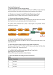
1
3URIHVVLRQDO'LPPHUV 6 '06HULHV 86(50$18$/ © 2001 by C.E. Studio-2 s.l. – Spain (EEC) http://www.ramaudio.com e-mail : [email protected] K3132-231 MOWDMDoc 2/01 DM Series - User manual INDEX INDEX...................................................................................................................................................1 DM SERIES DIMMERS ........................................................................................................................2 FEATURES AND TECHNICAL CHARACTERISTICS ........................................................................3 CONNECTIONS....................................................................................................................................4 CONTROL SIGNALS........................................................................................................................4 POWER SIGNAL ..............................................................................................................................5 GENERAL.............................................................................................................................................7 FRONTAL PANEL & INFORMATION.............................................................................................7 DMX ADDRESS - DIR....................................................................................................................8 DIMMER RESPONSE .......................................................................................................................9 LED INFORMATION........................................................................................................................9 PREHEAT FUNCTION - PRHT........................................................................................................9 CURVE MENU................................................................................................................................10 TEST MENU ...................................................................................................................................12 DMX-512 COMUNICATION FAULT ............................................................................................12 BACK-UP MENU, bACP..............................................................................................................13 COLD RESET..................................................................................................................................14 INSTALLATION AND START UP.....................................................................................................15 MAINTENANCE AND TECHNICAL SERVICE ................................................................................16 Miscellaneous ......................................................................................................................................17 RAM Lighting 1 DM Series - User manual DM SERIES DIMMERS The DM Series dimmers are devices offering high technical characteristics and full digital operation at reasonable cost. These units have been designed on the base of a new concept permitting different configurations from the same basic unit. The DM Series dimmers are perfect for fixed installations or touring multi-channel racks and furthermore are the ideal tool for Theatres, Auditoriums, Orchestras , Discotheques, TV studios and any event requiring precision light control. DM Series dimmer models: DM 615: 6 channels x 15A (3,5 KW) DM 615 S: 6 channels x 15A (3,5 KW) (Schukos) DM 1215: 12 channels x 15A (3,5 KW) DM 625: 6 channels x 25A (5,5 KW) This user manual is based mainly on DM 615 model, most functions are the same on the other models. 2 RAM Lighting DM Series - User manual FEATURES AND TECHNICAL CHARACTERISTICS FEATURES • DMX-512 Control Signal Input • DMX signal interruption options: Recall last DMX info,call recorded back-up Memory, All channels off • Analogue 0/+10V Control (Permits simultaneous operation with DMX) • LED indicators for each channel output regulation • LED indicator for DMX Input • LED indicator for internal power • Temperature Control with alert and disconnection • Input buffer test • Luminaries protection with a delay time (30ms) in the quick rises • Cold incandescent load at full rating without tripping • Microprocessor generated half-cycle point synchronized with each phase input which permits detection and isolation of any noise at the Power Mains • Numerical four digit Display for general information and Menu functions follow-up • Three Function Keys for Menu Address • Dimmer Curves: Linear, Square, Inverted Square, on/off and Park, auto-adjusting to the input Frequency. • Preheat level for all Dimmer channels • Input Mains: Cable, (Optionally, internal or external Screw terminal connection for 4-6 mm section cable) • Power Output: Screw terminal connection (Optionally, Harting type terminal). (615 S version with schuko outlets and cable mains input) • Dimensions 19" Standard Rack: · DM 615 model: 2U. Weight: 15 Kg · DM 615 S model: 3U. Weight: 15 Kg · DM 625 and DM 1215 models: 3U. Weight 20 Kg TECHNICAL CHARACTERISTICS • Channels and Capacity: · 6 x 3.5 KW (6 x 15A) · 12 x 3.5 KW (12 x 15A) · 6 x 5.5 KW (6 x 25A) • Slow start at turn on and slow rearm (2 s). Permits switching-on the Dimmer at full load. • 40/70 Hz Frequency Auto-Selection • Noise suppression to TV Studio specifications • Three phase operation with single phase emergency use • Unipolar Automatic Circuit Breaker per channel, optionally the Dimmers can be supplied with DPN Breaker • Fan cooling (temperature dependant) • AMECON® Suppression Chokes with linear response between 25% and full load and 120µs Rise Time • Power Devices: 25A Triac on the 3.5 KW models and 40A on the 5.5 KW • Turn on of Triacs when processor fully operative • 0/100% Duty Cycle RAM Lighting 3 DM Series - User manual MENUS • DMX Channel Address, Lineal • Preheat Function • Dimmer Curve Selection, Generic or per Channel • Test Functions: DMX, Analogue, Software MAINS • Three phase, neutral and earth • Working Conditions: Ambient Temperature -10ºC/35ºC • Relative Humidity, (Without condensation) 80% • Installation CAT: CAT II CONNECTIONS Options of configurations for mains power input and regulated power outputs: Main Power Input Regulated Power Output Model Bornes Housing Cable Bornes Harting Schukos DM 615 Standard Option Option Standard Option - DM 615 S - Standard Option - - Standard DM 1215 Standard Option Option Option Standard - DM 625 Standard Option Option Standard Option - CONTROL SIGNALS DMX-IN & DMX-THRU. In the frontal panel: 2 XLR-5 connectors. Code: GND. Pin 1 Data - Pin 2 Data + Pin 3 Use a shielded twisted pairs cable with 120 Ω characteristic impedance and low capacitance. Connect the shield to the pin number 1. Data - & Data + cables have to be in the same pair. Don’t use audio cables. 0 +10V. In the frontal panel: SUBD-15 male. Code by dimmer type: SUBD-15/ Nº PIN 1 2 3 4 5 6 7 8 DM 615 / Channel DM 1215 / Channel DM 625 / Channel NC = "non connected". 4 RAM Lighting 1 1 1 2 2 2 3 3 3 4 4 4 5 5 5 6 6 6 9 10 11 12 13 14 15 NC NC NC NC NC NC NC GND NC 7 8 9 10 11 12 NC GND NC NC NC NC NC NC NC NC GND NC DM Series - User manual POWER SIGNAL POWER INPUT: INSIDE SCREW TERMINALS. The dimmer has 4 screw terminals and 1 ground screw inside the unit for 4 mm cable (DM 615) or 6 mm cable (DM 625 y DM 1215). In the rear panel there is housing like access for the input cables. Code: Neutral N (blue) Phase R (brown) Phase S (grey) Phase T (black) And a ground screw for Ground. POWER INPUT: EXTERNAL SCREW TERMINALS. The dimmer has 5 screw terminals for 4 mm cable (DM 615) or 6 mm cable (DM 625 y DM 1215). Code: Neutral N (blue) Phase R (brown) Phase S (grey) Phase T (black) Ground (Yellow-green). ¡Always connect the input ground! REGULATED POWER OUTPUT Bornes (screw terminals). • • • • DM 615: 12 screw terminals/ 2,5 mm, labelled on the dimmer rear panel. DM 1215: 24 screw terminal/ 2,5 mm, labelled on the dimmer rear panel. DM 625: 12 screw terminals/ 4 mm, labelled on the dimmer rear panel. Ground screw. RAM Lighting 5 DM Series - User manual Harting. • • • DM 615: DM 1215: DM 625: 1 Harting - 16 x 16A 1 Harting - 24 x 16A. 2 Harting - 6 x 35A. DM 615 / HTS 16 x 16A Channel 1 PIN 1 Neutral 1 PIN 9 Channel 2 PIN 2 Neutral 2 PIN 10 Channel 3 PIN 3 Neutral 3 PIN 11 Channel 4 PIN 4 Neutral 4 PIN 12 ... ... Channel 6 PIN 6 Neutral 6 PIN 14 N.C. PINES 7, 8, 15 & 16. Models and their codes DM 1215 / HTS 24 x 16A Channel 1 PIN 1 Neutral 1 PIN 13 Channel 2 PIN 2 Neutral 2 PIN 14 Channel 3 PIN 3 Neutral 3 PIN 15 Channel 4 PIN 4 Neutral 4 PIN 16 Channel 5 PIN 5 ... ... Channel 12 PIN 12 Neutral 12 PIN 24 DM 625 / 2 HTS 6 x 35A Channel 1 PIN 1 of 1 Neutral 1 PIN 4 of 1 Channel 2 PIN 2 of 1 Neutral 2 PIN 5 of 1 Channel 3 PIN 3 of 1 Neutral 3 PIN 6 of 1 Channel 4 PIN 1 of 2 Neutral 4 PIN 4 of 2 Channel 5 PIN 2 of 2 Neutral 5 PIN 5 of 2 Channel 6 PIN 3 of 2 Neutral 6 PIN 6 of 2 Doubled Schukos. • For the special model DM 615 S (3U) only: 6 doubled Schukos, for the 6 regulated channels, numbered in the rear panel. ¡Always connect the protection ground for the load! The load terminals have 230V~. Maximum load.- 2,5kW (3 phases) or 850W (1 phase) Don’t connect equipment with accessible parts with voltage & without double isolation respect to its powered. 6 RAM Lighting DM Series - User manual GENERAL The DM Series dimmers offer the following software functions : Automatic adjusting to the input frequency. Microprocessor controlled zero crossing point detection. Slow rearm at turn on… These functions permit the DM Series dimmer working in less than optimal conditions, with power generators, in noisy environments, etc. The dimmers detect and isolate any noise in the power input to effectively avoid flickering. Slow rearm at turn on.- If the dimmer is switched on loaded, it takes 2 seconds fading up to the current output level to avoid excessive consumption in the turn on process. Automatic adjust with the input frequency.- This function eliminates flickering in the outputs. No adjusting is needed between 50 Hz and 60 Hz. Microprocessor controlled zero crossing point detection. To detect power input noise & avoid flickering in the outputs. FRONTAL PANEL & INFORMATION The frontal panel of the dimmers is: • • • • • • • • • 6 circuit breakers (12 for 12 channels dimmers). 6 green LEDs to show us the output levels, one by channel (12 for 12 channels dimmers). 1 Hole to access the internal Reset button. 1 red LED: DMX reception information. (DMX) 1 green LED: Internal power supply correct. (ON) 3 Function keys, MENU, ENTER & UP to use the dimmer menus. 1 Numerical Display with 4 digits, for general information & menus. DMX-IN & DMX-THRU connectors. Analogue input connector, 0+10V. The dimmer can work with 0+10V signal & DMX-512 signal at the same time, under HTP control. (High level Take the Priority). RAM Lighting 7 DM Series - User manual DMX ADDRESS - DIR To work with DMX-512 signal control, the dimmer needs one DMX address. This address is the address of the channel number 1, or starting address. The DM Series dimmers permit lineal patching. The DMX address can be 1 to 512. When we switch on the dimmer, the DMX address appears on the display. Example: A 6 channels DM dimmer has to respond to the DMX 13 to 18. In the DIR menu, edit the DMX address as 13. Access to the dimmer menus. The display shows the first menu: dir. MENU ENTER ENTER Select the display menu. This menu permit us to change the DMX starting address. The cursor is in the hundred digits, you can edit this number with the ↑ key. For this example, don’t edit this number. Accept the precedent data and proceed to edit the tens, now the cursor is in the tens digit. Press ↑ dir PrHt Cur TESt bACP 001 001 one time, to edit this number. 011 Accept the precedent data and proceed to edit the units. ↑ ENTER Press two times (until the 3 appears) 011 013 Press ENTER, to accept the DMX address and exit to the menu DIR. ENTER or MENU or Press MENU, to exit without accepting the DMX edited address. 13 or 1 Notes: If the DMX address is incorrect (for example: 000) the dimmer show us the message: ºErº. Edit one correct DMX address. We can exit to this menu at any time pressing the MENU key. In normal mode, the display shows: _ _ _1 The dimmer DMX address, in this case DMX 1. Display by default. 8 RAM Lighting DM Series - User manual DIMMER RESPONSE The DM dimmer has a response time of 30 ms, minimum time needed to pass for 0% to 100%. At this basic time response we can add the curve response (see the CURVE menu). LED INFORMATION These LEDs are located in the frontal panel of the DM dimmer, these LEDs are: • LED ON: “On”, if the internal power supply for the electronic is correct: 5Vdc. • LED DATA: Blinks when the DMX-INPUT connector receives a digital signal type RS485. • LED 1..6: Green LEDs, one by channel. These LEDs show us the output level of their respective channel. For the 12 channels dimmers, there are 12 green LEDs. PREHEAT FUNCTION - PRHT The DM dimmer permits us to set the preheating level, this level is applied to all dimmer channels. The level of preheating can be established between 0% - 99%. By default this function is set at 0% for all the dimmer channels. To change the preheat level: Access to dimmer menus. The display shows the first menu. MENU ↑ ENTER Scroll the main menu options. Press this key until the display show us the option: PrHt. This is the second option in the list. Access the preheat menu (PrHt). The first level digit is blinking, this digit can be edited with the ↑ key. Edit this digit and press ENTER to accept the numeric data. Now the cursor is in the units digit. Edit the units digit with the ↑ key. Press ENTER to accept the edited preheat level. The System return at the PRHT menu and the preheating level is activated fading in 2 sec. dir dir PrHt Cur TESt bACP 00 10 PrHt RAM Lighting 9 DM Series - User manual CURVE MENU The DM dimmer permits us to assign different response curves to its channels. By default the assigned curve, for all channels, is the lineal curve (lineal in power). The curves are: Lineal.- (Li) Lineal in power. Square -Television .- (SQ) Quick starting. Used in television studios. More precision between the 70% and the 100% of the output voltages. Invert Square.- (in) Slow starting. More precision between the 30% and the 50% of the output voltages. Used with fluorescence. ON/OFF.- (On) Non dim curve. Used with HMI lamps. PARK.- (PA) This curve maintains the channel at 100%, used for working lights... The curves in graphic mode: Tensión Salida 100 80 SINV SQRE Lineal ON-OFF PARK 60 40 20 Control 10 RAM Lighting 100 90 80 70 60 50 40 30 20 10 0 0 DM Series - User manual The curve menu, (Cur): Access to the dimmer menus. The display shows the first menu. dir dir PrHt Cur TESt bACP MENU Press this key until the display shows the Cur (Curves) menu. ↑ ENTER Access to the Cur menu. The display has 2 parts: The 2 firsts digits, now blinking, show the channel number, and the gn (generic) option to edit the same curve in all channels. Now, pressing to edit its curve. ↑ , we can select the desired channel in the display gnLo 1 Loo 2 L ... 6 Lo Example: Change the channel 2 curve. Select the channel 2 in the display (2 Lº). The 2 last digits show us the current selected curve for this channel. To edit the curve for the showed channel option. Now, the 2 last ENTER digits are blinking, and we can edit pressing the On-Off curve (Option: On). ENTER ↑ . Example: Select The 2 last digits are: Li: Lineal curve SQ: Square curve. In: Inverted square curve. On: ON/OFF curve PA: Park curve. Accept the edited data and return to the previous display. The curve is activated immediately. 2 2 2 2 2 Li SQ in On PA 2 Oo o Note that the current curve is marked with the symbol . If all channels have the same curve, at the beginning of this menu, in the generic option (gn) we can see o the curve marked with the symbol . RAM Lighting 11 DM Series - User manual TEST MENU The tests are: • d i g . DMX test or digital input test. We can see the input DMX signal by dimmer channel. • AnLg. ANALOGUE test. We can see the 0+10V input for dimmer channel. • SOFt. Show us the current software version. tESt menu: Access to the dimmer menus. The display shows the first menu. dir MENU Select the tESt option, pressing ↑ up to see this option in the display. ↑ ENTER ↑ ENTER tESt Access to tESt menu. The display shows the first option test. Note: The symbol () appears when the dimmer hasn’t any DMX input. dig AnLg SOFt 1 50 To select others TEST options. Select the shown option. The options Dig & AnLg: The display shows a 4 digits number, the first 2 digits are the channel (chan 1 @ 50%) numbers and the 2 last digits are the input level for this channel. To see the different channels press ↑ 2 FF . The SOFt options, the display shows the number of the current software version. MENU dig Return to the previous menu. Return to the main display pressing this key as many times as necessary. (chan 2 @ 100%) 1.00 dig DMX-512 COMUNICATION FAULTS When the DMX512 communication fails, the dimmer maintains in scene the last DMX information. This signal is in scene until the DMX512 communication failure is solved or until to the dimmer is switched off. The DM Series dimmer has a second option: the backup memory. This backup memory is accessed in the bACP menu. 12 RAM Lighting DM Series - User manual BACK-UP MENU, bACP When the DMX communication fails, the dimmer can maintain a scene with a backup memory, this memory is recorded in the bACP menu. This memory fades in the memory scene in 2 seconds, after a communication failure In this menu we can record the backup memory (REC) and activate this function (PLAY). When this function is deactivated and the DMX communication fails, the dimmer maintains the last DMX information. Access to the dimmer menus. The display shows the first menu. dir MENU ↑ ENTER ↑ MENU Select the bACP options in the display pressing ↑ as many times as necessary. Access to the bACP menu. The display shows the first option: PLAY, this option permits us to activate the backup memory function. To activate/deactivate this function press ENTER. The active function is marked with the symbol º, in the display: PlAº. When this function is deactivated, if the DMX communication fails, the dimmer maintains the last DMX information. bACP PlAY rEC Access to the rEC option to read the backup memory with the desired information. Select the desired “scene” (by DMX or 0+10V) and press ENTER. The scene is recorded with the current dimmer output status. Note: After a Cold Reset the backup memory is a blackout memory (all its channels @ 0%). The backup memory is recorded each time that you press ENTER here. rEC Return to the previous menu. Return to the main display pressing this key as many times as necessary. bACP RAM Lighting 13 DM Series - User manual COLD RESET The dimmer has a Reset push button (accessible by the small hole located under DATA LED). Warm Reset: • Press the Reset push button. After a Warm Reset the dimmer maintains the recorded data, and initialise the output buffer. Cold Reset: • Press and hold down the Reset push button, press and hold down the MENU key and release the Reset push button. Release the MENU key. After a Cold Reset, the dimmer is configured with: • DMX address: 001. • Preheat: 0% • Lineal curve for all channels. gnLº • Backup memory in all channels at 0%. Backup memory deactivated. Do a Cold Reset occasionally! After a Cold Reset in the display you can see: 14 RAM Lighting 1 DM Series - User manual INSTALLATION AND START UP WHEN YOU RECEIVE THE NEW DM DIMMER: • Unpack carefully the DM Series dimmer. • The dimmer is packed with the user manual, the control sheet and the guarantee card. • Preserve the original pack if you need to transport the dimmer. • Read the user manual, specially the section CONNECTIONS. • The main supply has to be protected with a general protection to disconnect the equipment, placed near the unit and clearly labelled. If the equipment is connected at a single phase, the connector can be considered the disconnection means for the unit. Maximum 3 meters long for the mains supply cable. • Protect the mains connection of this unit following the current norms (circuit-breaker and magnetothermal). • Connect the unit to the mains supply (WITHOUT POWER) 3 phase at 380V + neutral + ground to the screw-on terminals. If the unit has internal screw-on connection: • Place the unit in a flat surface. • Remove the upper cover by unscrewing the 6 screws. • Insert the mains cable through the hole in the rear of the unit. • Connect the 3 phase terminals, the neutral terminal and the ground terminal. • Close the upper cover. • Connect the unit outputs and their ground protection. • Connect the control signal: DMX and/or 0 +10V. • Observe that the ventilation’s grills are free. • Put all circuits breakers in their OFF position. • Turn on the mains supply. • Your DM dimmer should be working now. Press the RESET button. Set the DMX address. • Put all circuits breakers ON. • Switch on the control source (DMX and/or 0+10V). RAM Lighting 15 DM Series - User manual MAINTENANCE AND TECHNICAL SERVICE To manipulate the dimmer, disconnect it!. CLEANING External surfaces: Clean with a soft damp cloth. Internal surfaces: Vacum or compressed air jet. MAINTENANCE Internal cleansing: Annual. In especially "dirty" ambient (dust accumulation, smoke, confetti…) this task must be carried out quarterly. Adjustment of the pressure on the screw connections. Triennial. With touring equipment this period must be reduced to one year. 16 RAM Lighting DM Series - User manual Miscellaneous --- 1 MENU DMX address, editable with ↑ & ENTER dir ENTER 001 PrHt ENTER 00 Cur ENTER gnLº 1 Lº 2 Lº .... 6 Lº ENTER Preheat level, editable with ↑ & ENTER TESt ENTER digAnlg SOFt ENTER BACP ENTER PlAY rEC ENTER gnLi gnSQ gnin gnOn gnPA Lineal Square Invert S. On-Off Park 1 00 2 00 .... 6 00 PlAº RAM Lighting 17 Manufactured in the EEC by C.E. Studio-2 s.l. Pol. Ind. Aldaya - C/ Sierra Perenxisa, nº 20 46960 Aldaya - Valencia - SPAIN Phone: +34 96 127 30 54 Fax: +34 96 127 30 56 http://www.ramaudio.com e-mail: [email protected]