1
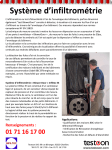
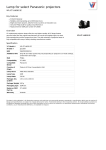
Operation Manual EN Mode d'emploi FR Gebruiksaanwijzing NL WWW.BEGLEC.COM Copyright © 2008 by BEGLEC cva. Reproduction or publication of the content in any manner, without express permission of the publisher, is prohibited. Version: 1.0 ENGLISH OPERATION MANUAL ENGLISH OPERATION MANUAL 7. Lower the upper section until there is at least 40cm distance between the top of the upper section and the top of the truss system. 8. Place the 120cm T-bars on the end of the upper sections and tighten knobs. 9. Raise stands to desired height and tighten knobs. 10. Install all par cans on top bars and truss system. ® Thank you for buying this JB Systems product. To take full advantage of all possibilities and for your own safety, please read these operating instructions very carefully before you start using this light bridge. Important: Overhead rigging requires extensive experience! Working load limits should be respected, certified installation materials should be used, the installed device should be inspected regularly for safety. Make sure the area below the installation place is free from unwanted persons during rigging and servicing. Always use a certified safety cable when installing a light effect in the light bridge. The light effect should be well fixed; a free-swingingmounting is dangerous and may not be considered! FEATURES OVERHEAD RIGGING Budget priced but multifunctional aluminium light bridge Composed of 2 light stands with T-bar and 2 truss elements. Both light stands with T-bar can be used separately! Perfect for mobile DJs: can be loaded in any car! Distributed load up to 100kg! Width between stands = 3m Total width with T-bars installed = 4,2m Maximum height = 3,25m MAINTENANCE BEFORE USE Before you start using this light bridge, please check if there’s no transportation damage. Should there be any, do not use the light bridge and consult your dealer first. Important: This light bridge left our factory in perfect condition and well packaged. It is absolutely necessary for the user to strictly follow the safety instructions and warnings in this user manual. Any damage caused by mishandling is not subject to warranty. The dealer will not accept responsibility for any resulting problems caused by disregarding this user manual. Keep this booklet in a safe place for future consultation. If you sell the light bridge, be sure to add this user manual. SAFETY INSTRUCTIONS: Important: The installation must be carried out by qualified service personal only. Improper installation can result in serious injuries and/or damage to property. Due to safety reasons it is prohibited to make unauthorized modifications to the unit. Make sure the area below the installation place is free from unwanted persons during servicing. The installations should be inspected every year by a skilled person to be sure that safety is still optimal. During inspection the following points should be checked: All screws used for installing should be tightly fastened and may not be corroded. All the parts from the light bridge should be totally free from any deformation. SPECIFICATIONS Max. distributed load: Weight complete bridge: Height complete bridte: Width between stands: Total width incl T-bars: Truss elements (2pcs): T-bar size: Light stands – top section: Light stands – middle section: Light stands – base section: 100kg 20kg 1,62m to 3,25m 3m 4,2m L=1,5m/pc, total=3m (tube=38mm) 1,2m (D=38mm) H=84cm, 2 preset holes (D=38mm) H=96cm, 5 preset holes (D=41mm) H=130cm (D=45mm) Every information is subject to change without prior notice You can download the latest version of this user manual on our website: www.beglec.com ASSEMBLY INSTRUCTIONS The LB30 is composed of 2 telescopic light stands with T-bar and 2 vertical truss elements. The 2 telescopic light stands have 3 sections. Remark: the numbers below correspond to the numbers on the drawing. 1. For your convenience, set the vertical sections on the lighting stands to 46cm above the upper base (clutch) of the lower section. 2. Set legs to the desired base spread: 90 to 120cm 3. Assemble the 2 truss ends with the center adapter to obtain a solid 3m long truss. Once assembled tighten knobs on center adapter. 4. Place both lighting stands approximately 3m apart. 5. Slide the end of the truss into tubing adapters on lighting stand sections. 6. Once truss is inserted at both ends tighten knobs on adapters. JB SYSTEMS® 1/6 LB-30 JB SYSTEMS® 2/6 LB-30 FRANÇAIS MODE D’EMPLOI FRANÇAIS MODE D’EMPLOI INSTRUCTIONS DE MONTAGE Le LB30 est compose de 2 stands télescopiques avec T-bar et de 2 structures de pont. Les 2 stands télescopiques sont divisés en 3 sections. ® Merci d’avoir choisi ce produit JB Systems . Pour votre sécurité et pour une utilisation optimale de toutes les possibilités, lisez attentivement cette notice avant utilisation. EN VOUS INSCRIVANT POUR LA LETTRE D’INFORMATION VOUS SEREZ TOUJOURS TENU AU COURANT DES DERNIERES NOUVELLES CONCERNANT NOS PRODUITS: NOUVEAUTÉS, ACTIONS SPECIALES, JOURNEES PORTES OUVERTES, ETC. SURFEZ SUR: WWW.BEGLEC.COM CARACTERISTIQUES Pont économique multifonctionnel en aluminium Composé de 2 stands avec T-bar et 2 éléments de pont. Les 2 stands avec T-bar peuvent être utilisés séparément! Parfait pour le DJ mobile: peut être rangé dans n’importe quel type de voiture! Charge répartie jusqu’à 100kg! Distance entre les stands = 3m Largeur totale avec les T-bars installés = 4,2m Hauteur maximale = 3,25m AVANT UTILISATION Avant d’utiliser ce pont, assurez-vous de l’absence de dommages liés au transport. En cas de dommages, n’utilisez pas le pont et contactez le vendeur. Important: ce pont a quitté notre usine en parfaite condition et bien emballé. Il est primordial que l’utilisateur suive les instructions de sécurité et avertissements inclus dans ce manuel. La garantie ne s’applique pas en cas de dommage lié à une utilisation incorrecte. Le vendeur ne prend pas la responsabilité des défauts ou de tout problème résultant du fait de n’avoir pas tenu compte des mises en garde de ce manuel. Conservez ce manuel dans un endroit sûr pour toute consultation future. Si vous vendez l’appareil, assurez-vous d’y joindre ce manuel également. Afin de protéger l’environnement, merci de recycler les emballages autant que possible. INSTRUCTIONS DE SECURITE: Important: L’installation doit être faite par du personnel qualifié uniquement. Une installation incorrecte peut causer des blessures sévères et/ou endommager l’unité. Pour des raisons de sécurité, il est interdit d’apporter une quelconque modification à l’unité non spécifiquement autorisée par les parties responsables. INSTALLATION DE PROJECTEURS EN HAUTEUR Important: L’installation en hauteur d’appareils exige de l’expérience ! Les limites de charge doivent être scrupuleusement respectées, du matériel d’installation certifié doit être utilisé, et l’appareil installé doit subir des inspections de sécurité régulièrement. Assurez-vous que la zone au-dessous du lieu d’installation ne comporte pas de personnes non concernées lors de l’installation, la désinstallation ou la maintenance. Utilisez systématiquement un câble de sécurité lors de l’installation d’appareils dans le pont. Les appareils doivent être bien fixés, un montage à balancement est dangereux et ne devrait pas être pris en considération ! Remarque: les numéros ci-dessous correspondent aux numéros qui figurant sur le dessin. 1. Pour votre facilité, réglez les sections verticales des stands 46cm au dessus du haut de l’embase (ou les 3 pieds se rejoignent). 2. Réglez l’écartement de la base du stand: de 90 à 120cm 3. assemblez les 2 structures de pont à l’aide de l’adaptateur central. Vous obtenez ainsi une structure de pont solide de 3mètres de long. Une fois assemblé, serrez les boutons de l’adaptateur central. 4. Placez les 2 stands à environ 3mètres l’un de l’autre. 5. Glissez les extrémités des structures de pont dans les adaptateurs de tubes qui se trouvent sur les stands. 6. Dès que les structures sont insérées : serrez les boutons des adaptateurs. 7. Descendez la section supérieure jusqu’à ce qu’il y ait une distance d’au moins 40cm entre le haut de mat et la partie supérieure des structures. 8. Placez les T-bars de 120cm sur le haut de mat et serrez les boutons de serrage. 9. Réglez la hauteur des stands selon vos désirs et serrez les boutons. 10. Installez tous les projecteurs sur les structures et T-bars. MAINTENANCE Assurez-vous que la zone au-dessous du lieu d’installation ne comporte pas de personnes non concernées lors de la maintenance Les installations doivent être inspectées chaque année par du personnel qualifié pour assurer une sécurité optimale. Pendant l’inspection, les points suivants doivent être vérifiés : Toutes les vis de chacune des pièces doivent être bien fixées et non corrodées. Toutes les pièces du pont doivent être totalement intactes, sans aucune déformation. SPECIFICATIONS Charge Max. répartie: Poids du pont complet: Hauteur du pont complet: Distance entre les pieds: Largeur totale, T-bars inclus: Structures de pont (2pcs): Dimensions du T-bar: Pieds – section du dessus: Pieds – section du milieu: Pieds – embase: 100kg 20kg 1,62m to 3,25m 3m 4,2m L=1,5m/pc, total=3m (tube=38mm) 1,2m (D=38mm) H=84cm, 2 trous (D=38mm) H=96cm, 5 trous (D=41mm) H=130cm (D=45mm) Chacune de ces informations peut être modifiée sans avertissement préalable. Vous pouvez télécharger la dernière version de ce mode d’emploi de notre site Web: www.beglec.com JB SYSTEMS® 3/6 LB-30 JB SYSTEMS® 4/6 LB-30 NEDERLANDS HANDLEIDING NEDERLANDS HANDLEIDING MONTAGEVOORSCHRIFTEN De LB30 is samengesteld uit 2 telescopische lichtstatieven met T-bar en 2 vlakke truss elementen. De 2 telescopische lichtstatieven hebben 3 secties. ® Hartelijk dank voor de aankoop van dit JB Systems product. Om ten volle te kunnen profiteren van alle mogelijkheden en voor uw eigen veiligheid, gelieve de aanwijzingen zeer zorgvuldig te lezen voor U de lichtbrug gebruikt. DOOR U OP ONZE MAILINGLIJST IN TE SCHRIJVEN ONTVANGT U STEEDS DE LAATSTE INFORMATIE OVER ONZE PRODUCTEN: NIEUWIGHEDEN, SPECIALE ACTIES, OPENDEURDAGEN, ENZ. SURF NAAR: WWW.BEGLEC.COM KARAKTERISTIEKEN Budgetvriendelijke, doch multifunctionele aluminium lichtbrug Samengesteld uit 2 lichtstatieven met T-bar en 2 truss elementen. Beide lichtstatieven met T-bar kunnen apart gebruikt worden! Perfect voor de mobiele DJ: kan vervoerd worden met elk type auto! Verspreide belasting tot 100kg! Afstand tussen de statieven = 3m Totale breedte met de T-bars geïnstalleerd = 4,2m Maximum hoogte = 3,25m VOOR DE INGEBRUIKNAME Controleer voor het eerste gebruik van de lichtbrug of deze tijdens het transport beschadigd werd. Mocht er schade zijn, gebruik de lichtbrug dan niet, maar raadpleeg eerst uw dealer. Belangrijk: deze lichtbrug verliet de fabriek in uitstekende staat en goed verpakt. Het is erg belangrijk dat de gebruiker de veiligheidsaanwijzingen en raadgevingen in deze gebruiksaanwijzing uiterst nauwkeurig volgt. Elke schade veroorzaakt door verkeerd gebruik valt niet onder de garantie. De dealer aanvaardt geen verantwoordelijkheid voor mankementen en problemen die komen door het veronachtzamen van deze gebruiksaanwijzing. Bewaar deze gebruiksaanwijzing op een veilige plaats om hem in de toekomst te kunnen raadplegen indien nodig. Indien U de lichtbrug verkoopt, gelieve dan deze gebruiksaanwijzing bij te voegen. VEILIGHEIDSVOORSCHRIFTEN Belangrijk: De installatie van het toestel mag uitsluitend door bekwaam onderhoudspersoneel uitgevoerd worden. Onjuiste plaatsing kan ernstige letsels en/of schade tot gevolg hebben. Om veiligheidsredenen is het verboden om modificaties aan de lichtbrug aan te brengen. OPHANGEN VAN TOESTELLEN Belangrijk: Het ophangen vergt veel ervaring. U behoort de grenzen te respecteren aan de werklast; erkende installeringmaterialen moeten worden gebruikt; de veiligheid van de installatie moet regelmatig worden gecontroleerd. Overtuig U ervan dat het gebied onder installatieplaats vrij is van ongewenste personen tijdens het plaatsen, het weghalen en het onderhoud. Gebruik bij het installeren van het toestel altijd een gehomologeerde veiligheidskabel Het apparaat moet goed worden vastgezet; aan een vrij zwaaiende montage mag zelfs niet gedacht worden. Opmerking: de nummers hieronder komen overeen met de nummers op de tekening. 1. Zet voor uw gemak de verticale secties van de lichtstatieven ongeveer 46cm boven het bovenste deel van de basis (waar de 3 poten samenkomen). 2. Regel de spreiding van de poten: 90 tot 120cm 3. Assembleer de 2 truss uiteinden door middle van de centrale adapter zodat u een truss van 3m bekomt. Eenmaal de stukken zijn samengevoegd moet u de vijsknoppen van de centrale adapter vastzetten. 4. Plaats beide lichtstatieven op een afstand van ongeveer 3m van elkaar. 5. Schuif de uiteinden van de truss in de buisadapters van de lichtstatieven. 6. Als de truss aan beide kanten in de buisadapters zit, span dan de vijsknoppen van de adapters aan. 7. Beweeg de bovenste sectie tot er zich minstens 40cm bevindt tussen de bovenkant van het statief en de bovenkant van het truss systeem. 8. Plaats de 120cm T-bars bovenop de lichtstatieven en vijs de spanknoppen vast. 9. Breng de statieven op de gewenste hoogte en zet de spanknoppen vast. 10. Installeer alle projectoren op de T-bars en het truss systeem. ONDERHOUD Overtuig U ervan dat het gebied onder de installatieplaats vrij is van ongewenste personen tijdens het onderhoud. Elk jaar moeten de installaties worden gekeurd door een vakman om te controleren of de veiligheid nog steeds perfect is. Bij inspectie moeten de volgende punten worden gecontroleerd. Alle schroeven en alle onderdelen moeten goed vastgedraaid zijn en mogen niet verroest zijn. De onderdelen van de lichtbrug mogen absoluut niet beschadigd of verwrongen zijn. TECHNISCHE KENMERKEN Max. verdeelde last: Gewicht volledige lichtbrug: Hoogte volledige lichtbrug: Afstand tussen de statieven: Tatale breedte incl T-bars: Truss elemenen (2pcs): Afmetingen T-bar: Statieven – top sectie: Statieven – middelste sectie: Statieven – basis: 100kg 20kg 1,62m tot 3,25m 3m 4,2m L=1,5m/pc, totaal=3m (buis=38mm) 1,2m (D=38mm) H=84cm, 2 gaten (D=38mm) H=96cm, 5 gaten (D=41mm) H=130cm (D=45mm) Elke inlichting kan veranderen zonder waarschuwing vooraf U kan de laatste versie van deze handleiding downloaden via Onze website: www.beglec.com JB SYSTEMS® 5/6 LB-30 JB SYSTEMS® 6/6 LB-30