1
Leader Light s.r.o.
M.Gorkeho 33
SK-052 01 Spisska Nova Ves
Slovakia
www.leaderlight.eu
01
WARNING!!!
Carefully read before installing, powering or servicing.
Nothing to do if anything misunderstand!
Only for professional use!
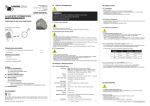
LL LED POINT
LL39 510x
COMPLIMENTS ON YOUR PURCHASE!
03 INSTALLATION
03.1 Unpacking
USER MANUAL
LL39 500
SAFETY INFORMATION
- Unpack carefully.
- This is electronic equipment and should be handled carefully.
- Damaged delivered package or if are any mechanical parts broken – it must be claim
immediately by the transport company.
Photo pictures as evidence are valuable for future claim.
03.2 Physical installation
- Loading capacity of bearing area has to be at least 10 times the weight of all device clusters
(luminaries, clamps, cables, ...).
- Heigrbreadth from combustible materials is 0,5m.
01.1 Risk of eyes damage
All dimensions are in milimeters
49
- Do not look directly into LED lamps.
- Do not look into light beam from a distance of less than 40 cm (16 inches)!
49
Φ
03.3 Electrical installation
01.2 Protection from electric shock
Following items are included:
- Fitting LL LED POINT with 1,5 m cable and 6 PIN LINE connector
1 pc.
- User manual
1 pc.
- Shut down power before installation or maintenance.
- Luminaries, Splitters, Driver and recommended power supply must be installed by a qualified
professional in accordance with relevant local codes.
Only acceptable source of AC power and frequency that complies with local buidling and electrical
codes to use.
- Do not use or do not connect the products if the power cable, power plug or fixtures are any way
damaged, wet, or if they are overheating.
- Do not modify, alter, or attempt to service the LeaderLight appliance.
Doing so will void the warranty.
- Before removing or installing any cover or part of appliance disconnect it from AC power.
- To tackle all Safety Information- 01!
- You can suffer a dangerous electric shock by using a high voltage AC/DC power
supply - by touching the AC/DC power supply wires inside LL LED POINT!
- LL LED POINT must be operated only with LL LED POINT SPLITTER.
- After installing the LL LED Z-POWER DRIVER, which is connected to the device - MW power
supply IN:100-260AC/ OUT: 24V you are ready to make the connections from fixtures to
LL LED SPLITTER.
- It is not necessary to open fixture before connecting to LL LED SPLITTER.
- Pull the 6PIN LINE cable connector from the fixtures to the LL LED SPLITTER output.
- Wire the Brown, Red, White, Green, Black, Blue wires of each fixture into the connector
terminals - see table „Wire colour to connector terminals“.
- LL LED SPLITTER operate with LL LED Z-POWER DRIVER.
- Connection ability - see pictures “Electrical Connections”.
01.3 Fire prevention
Additional items needed:
- LL LED POINT SPLITTER – must be ordered separately!!!
- LL LED Z-POWER Driver
- DC Power supply 24V
-
Follow all safety considerations.
Device never shield – minimum distance around fitting must be 100mm (4 in.).
LEDs never direct cover with filters or other materials.
Allowing max. ambient temperature is 40°C (104°F).
- Mounting accessories LL41 200, LL41 210, LL41 300
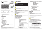
02 PRODUCT SPECIFICATION
Content:
02.1 Technical Specification
Lamp type:
01 SAFETY INFORMATION
01.1 Risk of eyes damage
01.2 Protection from electric shock
01.3 Fire prevention
02 PRODUCT SPECIFICATION
02.1 Technical Specification
02.2 Back panel
03 INSTALLATION
03.1 Unpacking
03.2 Physical installation
03.3 Electrical installation
04 MAINTENANCE
Lifetime:
Optic:
Control data Input:
Input power:
DC Power Connection:
Net weight:
Dimensions HxΦ:
ENVIRONMENT
IP:
Ambient temp. (Ta):
Cooling:
Do not throw away the appliance with the normal household waste at the end of its life,
but hand it in at an official collection point for recycling. By doing this, you help to preserve
the environment.
©MMVIII - Leader Light – All right reserved
WARNING!!!
LL LED POINT OPERATE ONLY with LL LED POINT SPLITTER!
Materials and finish:
Installation:
OneChip: RGB 3x1W P5 (Red, Green and Blue)
OneColour: 1xR/G/B/A/W/N P4
(Red or Green or Blue or White - 6300K or Amber or Neutral
White - 3000K)
Long 60 000 hrs 60% degradation
RGB: 35mm standard 25°, optional 40° - on request
OneColour: 35mm standard 25°, optional 10°, 40° - on request
RGB: 3 channels dimming with SPLITTER
OneColour: 1 channel dimming with SPLITTER
6 x LL LED POINT RGB + LL SPLITTER RGB: max. 25W
6 x LL LED POINT OneColour + LL SPLITTER GBWN: max. 8,5W
04 MAINTENANCE
- To tackle all Safety Information- 01!
- Damage caused by inadequate cleaning or maintenance is not coverd by warranty.
- Regular cleaning is demand (dust, dirt, ...).
24V DC 1,5m cable with 6pin LINE connector to SPLITTER
0,2 kg
40mm x 49mm without bracket
IP43 or IP65 on request
Maximum 40°C
Maintenance policy:
- Unplug mains befor maintenance and at least 10 minutes cool off.
- Cleanup dust from scuttle, diffuser and lens.
- Use vacuum or dampy duster (warm watter).
- Before reinstalling to check failure-free state – no wet parts!
Conventional
Housing: powder-painted anodized aluminium RAL9006 (other
colours on request)
Any position for ceiling, wall and surface mounting
Edition: A - 2008
If you have any question please, contact [email protected]
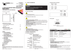
LL LED POINT ELECTRICAL CONNECTIONS with SPLITTER
LL LED POINT RGB SPLITTER connection with LL LED POINT RGB/AWB (max. 6 pcs.)
LL LED POINT RGB SPLITTER connection with LL LED POINT G/B/W/N (max. 6x2 pcs.)
LL LED POINT RGB SPLITTER connection with LL LED POINT R/A (max. 6pcs.)
DC 24V
DC 24V
ACACAC
ACACAC
ACACAC
POWER
SUPPLY
MW 240
DIN 24
24V
ACACAC
24V
ACACAC
black
red
R+ R- G+ G- B+ B-
black
green
black
green
R+ R- G+ G- B+ B-
24V
R+ R- G+ G- B+ B-
brown
red
white
green
black
blue
ACACAC
POWER
SUPPLY
MW 240
DIN 24
max.10A
max.10A
DC 24V
100-260V AC
100-260V AC
POWER
SUPPLY
MW 240
DIN 24
max.10A
100-260V AC
LL LED POINT G/B/W/N SPLITTER connection only with LL LED POINT G/B/W/N (max. 18pcs.)
LL LED POINT R/A SPLITTER connection only with LL LED POINT R/A (max. 18pcs.)
Maximal allowed amound of fixtures per SPLITTER
LL LED POINT RGB SPLITTER
6 pcs.
DC 24V
A= Anode
C= Cathode
POWER
SUPPLY
MW 240
DIN 24
max.10A
100-260V AC
black
red
black
red
black
red
A C A C AC
24V
A C A C AC
black
green
black
green
black
green
DC 24V
24V
A= Anode
C= Cathode
POWER
SUPPLY
MW 240
DIN 24
max.10A
LL LED POINT OneChip RGB
LL LED POINT G, B, W, N SPLITTER
6x3 pcs.
LL LED POINT OneColour G/B/W/N
LL LED POINT R, A SPLITTER
6x3 pcs.
LL LED POINT OneColour R/A
100-260V AC
Wire colour to connector terminals
RGB SPLITTER
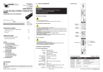
MOUNTING ACCESSORIES
Mounting on ceiling and wall is easy using various accessories as seen below.
1.1 Mounting on surface with
point bracket LL41 300
1.2 Mounting with surface
holder without cable space
LL41 200
1.1
1.2
1.3 Mounting with surface
holder with cable space
1.3 LL41 210
Connection conditions:
Connector
terminal
SPLITTER
G, B, W, N
SPLITTER
R, A
Connector
terminal
Wire
colour
R+
Brown
A
Black
R-
Red
C
Green (Blue)
Red
G+
White
A
Black
Black
Wire colour
Black
G-
Green
C
Green (Blue)
Red
B+
Black
A
Black
Black
B-
Blue
C
Green (Blue)
Red
• Each SPLITTER OUT to fitting must be connected
• Maximal allowed current on SPLITTER OUT is 3x0,35A
• Maximal distance from fixtures to driver is 50m (164 feet) dependence on cable diameter
Order code
Product name
• Never use more fittings as maximal allowed amound
LL39 500
LL LED POINT OneChip RGB
3x0,35A
LL39 510x
LL LED POINT OneColour
1x0,35A
• LL LED POINT SPLITTER is calculated only fo r LL LED POINT fixtures
Current
If you have any question please, contact [email protected]