1
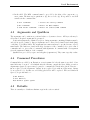
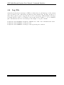
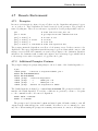
MuBSy
Id.: INTRO
Version: 4.3
Date: October 28, 2003
Revised: October 28, 2003
M B S
ulti
ranch
ystem
GSI Multi-Branch System
User Manual
H.G. Essel, N. Kurz
October 28, 2003
GSI, Gesellschaft f¨
ur Schwerionenforschung mbH
Planckstraße 1, D-64291 Darmstadt
Germany
Tel. (0 6159) 71–0
List of Figures
2.1
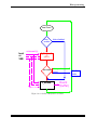
Environment Tasks . . . . . . . . . . . . . . . . . . . . . . . . . . . . . . . . . . . .
3.1
3.2
Hardware Configuration with CVC . . . . . . . . . . . . . . . . . . . . . . . . . . . 19
Hardware Configuration with VME . . . . . . . . . . . . . . . . . . . . . . . . . . . 20
4.1
4.2
Local Commands and Messages . . . . . . . . . . . . . . . . . . . . . . . . . . . . . 22
Local and Remote Commands and Messages . . . . . . . . . . . . . . . . . . . . . . 27
5.1
Connections and Servers . . . . . . . . . . . . . . . . . . . . . . . . . . . . . . . . . 36
6.1
6.2
Branch and Pipes . . . . . . . . . . . . . . . . . . . . . . . . . . . . . . . . . . . . . 47
Buffers and Streams . . . . . . . . . . . . . . . . . . . . . . . . . . . . . . . . . . . 49
7.1
Multi-Layer Structure . . . . . . . . . . . . . . . . . . . . . . . . . . . . . . . . . . 66
10.1
10.2
10.3
10.4
Histogram Access, one Base . .
Histogram Access, two Bases .
Histogram Data Base Structure
On-line Analysis Flow Chart .
Version 4.3 October 28, 2003
.
.
.
.
.
.
.
.
.
.
.
.
.
.
.
.
.
.
.
.
.
.
.
.
.
.
.
.
.
.
.
.
.
.
.
.
.
.
.
.
.
.
.
.
.
.
.
.
.
.
.
.
.
.
.
.
.
.
.
.
.
.
.
.
.
.
.
.
.
.
.
.
.
.
.
.
.
.
.
.
.
.
.
.
.
.
.
.
.
.
.
.
.
.
.
.
.
.
.
.
.
.
.
.
.
.
.
.
.
.
.
.
.
.
.
.
9
108
109
110
113
1
2
Version 4.3 October 28, 2003
MBS Copy Right
Chapter 1
Preface
GMC EDIT
GOOSY Copyright
The GOOSY software package has been developed at GSI for scientific applications. Any distribution or usage of GOOSY without permission of GSI is not allowed. To get the permission, please
contact at GSI Mathias Richter (tel. 2394 or E-Mail ”[email protected]”) or Hans-Georg Essel
(tel. 2491 or E-Mail ”[email protected]”).
MBS Copyright
The MBS software package has been developed at GSI for scientific applications. Any distribution
or usage of MBS without permission of GSI is not allowed. To get the permission, please contact
at GSI Mathias Richter (tel. 2394 or E-Mail ”[email protected]”) or Hans-Georg Essel (tel. 2491
or E-Mail ”[email protected]”), or Nikolaus Kurz (tel. 2979 or E-Mail ”[email protected]”).
Conventions used in this Document
Examples in this manual show both system output (prompts, messages, and displays) and user
input, which are all written in typewriter style. Names and keywords are also in typewriter
style. Items to be replaced by actual values are enclosed in <>.
The change bars mark changes between MBS and SBS.
Registered Trademarks are not explicitly noted.
Version 4.3 October 28, 2003
3
GMC READER
1.1
Intended Readers
GSI Multi-Branch System User Manual:
1.1.1
New Users of MBS
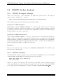
Overview Chapter 2, page 7
Hardware Chapter 3, page 17
Command Interface Chapter 4, page 21
Running a Data Acquisition Chapter 5, page 29
Event Serving and Filtering Chapter 9, page 87
1.1.2
Experienced Users of SBS
Release Notes Chapter 14, page 153
Readout Control Chapter 6, page 47
Multi-Layer Multi-Branch Systems Chapter 7, page 65
Data Structures Chapter 8, page 73
1.1.3
Optional Facilities
Histogramming Chapter 10, page 107
1.1.4
Reference Chapters
ESONE Library Chapter 11, page 117
Keyword Summary Chapter 12, page 121
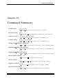
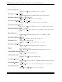
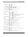
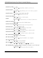
Command Summary Chapter 13, page 141
4
Version 4.3 October 28, 2003
MBS Copy Right
1.1.5
List of all Chapters
Overview Chapter 2, page 7
Hardware Chapter 3, page 17
Command Interface Chapter 4, page 21
Running a Data Acquisition Chapter 5, page 29
Readout Control Chapter 6, page 47
Multi-Layer Multi-Branch Systems Chapter 7, page 65
Data Structures Chapter 8, page 73
Event Serving and Filtering Chapter 9, page 87
Histogramming Chapter 10, page 107
ESONE Library Chapter 11, page 117
Keyword Summary Chapter 12, page 121
Command Summary Chapter 13, page 141
Release Notes Chapter 14, page 153
1.2
1.2.1
Other Manuals
GSI Multi-Branch System Reference Manual
Command and function descriptions.
Version 4.3 October 28, 2003
5
GMC MBS AUTHOR
1.3
MBS Authors and Advisory Service
The authors of MBS and their main fields for advisory services are (phone GSI: + 6159 71 - ):
R. Barth
Y. Du
Fastbus SMI library (Tel. 2554)
Event routines, DECunix port, AIX port (1995-1996)
H.G. Essel
Multitasking, CI, message logger, ESONE, GOOSY connections (Tel. 2491)
R. Fritzsche
TCP library.
H. G¨
oringer
Event server, PAW connections (Tel. 2553)
J. Hoffmann
CVC hardware, trigger (Tel. 2494)
F. Humbert
Esone library (1996)
N. Kurz
Lynx, setup, readout, collector, multi-branch systems (Tel. 2979)
R.S. Mayer
W. Ott
D. Schall
Event server, error/message handling (1992-1995)
Message logger, transport, stream server, taping (Tel. 2979)
CVC hardware, trigger (left GSI in 1996)
The authors thank Margareta Hellstr¨
om and Piotr Koczon for useful hints and for reviewing this
manual resulting in substantial enhancements. Further suggestions to enhance the manual are
welcome. The manuals are accessible also through WWW:
http://www-gsi-vms.gsi.de/img/doc or
http://www-gsi-vms.gsi.de/daq/home
[email protected].
6
Version 4.3 October 28, 2003
Summary
Chapter 2
Overview
GMC MBS INTRO
2.1
Summary
The Multi-Branch System (MBS) runs under the operating system Lynx OS (v2.5), a realtime
UNIX system. Almost all of the software is written in GNU C. The tcsh shell must be used in
order to run the system. The software runs on the GSI developed CAMAC processor board CVC,
on the ELTEC E6 and E7 VME processors and on VME PowerPC platforms (CES RIO2).
Although the data acquisition system is called Multi-Branch System (MBS) it is in fact
scalable from small single-crate CAMAC or VME systems, single branch systems with multiple
intelligent controllers to large hierarchical structured (multi-layered) multi-branch systems. CAMAC, VME and FASTBUS are supported. The data bus between crate controllers and event
builders can be memory mapped like VME bus, differential VSB bus and PVIC (CES), or transfer
oriented like Ethernet.
The data access from the controller which controls the branch (branch master) to slave controllers is provided by address mapped windows. These address windows can be specified freely in
a setup database (multi-window system). The system works standalone, i.e. no other computers
are necessary to take data and store it on a local tape. For on-line analysis, however, workstations
are needed (i.e. running GOOSY or PAW).
2.2
Command Interface
The MBS is controlled from ASCII terminals (VT type) through a command interface. The MBS
commands are composed of up to three command keywords followed by named arguments and
qualifiers. The commands are not implemented directly in the shell. They are dispatched from
dispatcher or prompter programs and executed by tasks running either on local or remote nodes.
Version 4.3 October 28, 2003
7
GSI Multi-Branch System User Manual: Overview
Command and argument specification can be stored in text files. Each command is executed by
a routine. All keywords may be abbreviated, e.g.
SET VERBOSE EVENT or SET VER EV
START TASK
or STA TA
The command arguments can be input in a positional order, by name reference or as qualifiers:
START TASK <name>
START TASK file=<path> name=<task>
SHO COMMAND -FULL
The interface executes command files and allows for recalling of command lines. All command
input except strings enclosed in ”” or beginning with a slash is changed automatically
to lowercase as the command definitions are. See more in 4, page 21.
2.3
Help
The documentation of all MBS commands and modules is done using the GSI documentation
tools. The help libraries are available on Lynx by command help. It works similar as the VMS
HELP.
help
help
help
help
help
help
-<lib>
-<lib> <key1>
<key>
-mbs
-goosy
list of available libraries
content of speficied library
next level
search key in all libraries
MBS help library
GOOSY help library (DAQ commands)
Currently the mbs help file mbs.hlp is generated on OpenVMS and then moved to directory
$HELPDIR = $MBSROOT/lib. The helpfile is generated from $MBSROOT/set/mbscom.cdf and
$MBSROOT/set/utilcom.cdf.
2.4
News
There is a news tool which can be called from shell or from dispatcher by command news.
Currently news for lynx and for daq are available:
news
news daq
news lynx
news daq -a
(get list of available news)
(get list of unseen topics)
(get list of all topics)
The news files are on directory $NEWSDIR = /mbs/news.
8
Version 4.3 October 28, 2003
MBS Environment
2.5
MBS Environment
Software Components
pipe
Readout
pipe
Slave
Readout
Slave
Master
Readout
Collector
Master
pipe
Tape/
Disk
TCP
Message
logger
Transport
Event
server
Esone
server
PAW
GOOSY
Utilities
Command
dispatcher
Application
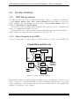
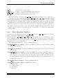
Figure 2.1: MBS Components
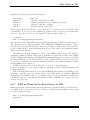
Figure 2.1 shows the main components of MBS which will be described briefly in the following
sections. MBS components are tasks executing commands. Both terms are used in this manual.
These components can be started from the shell or run in background. In the first case, they get
the commands from the terminal, in the second case from a dispatcher program. Thus several
components can be controlled from one terminal.
The set of components controlled from one terminal is called environment. There are one
local and optionally several remote environments. Each environment has one dispatcher and
one message logger. On the node of the local environment the prompter is used to dispatch
commands. If there are no remote environments, the dispatcher is used instead of the prompter.
The tasks communicate through common memory sections or message files. There are two
kinds of tasks: Known and Unknown. Tasks which execute commands must be known to the
dispatcher, because the dispatcher must send the commands to these tasks. These known tasks
are forked (started in background) directly by the dispatcher by the START TASK command. The
dispatcher can also start tasks which do not execute commands. These unknown tasks are forked
as childs of the Lynx INIT task. They are shown as detached by the dispatcher. Known tasks
can only run once at the same time.
Version 4.3 October 28, 2003
9
GSI Multi-Branch System User Manual: Overview
2.5.1
Command Dispatcher
See figure 2.1. This program (m dispatch) is started by alias mbs to control components running
in its environment. It can be called only once on a Lynx system. It executes the following
functions:
◦ Start message logger.
◦ Start/Stop tasks.
◦ Dispatch Commands.
The components are forked. MBS commands are dispatched to the task where the command is
executed. The dispatcher hibernates until it gets an acknowledge message from the task. The
tasks executing the command can use the terminal for output, but should normally send their
output to the message logger (see below). The dispatcher can be left by commands EXIT or QUIT
and restarted. It then acknowledges all known tasks. Do not leave the dispatcher by CTRL-Z!
This kills all tasks. See also 4.2, page 21.
2.5.2
Message Logger
See figure 2.1. This program (m msg log) is started automatically when running the dispatcher
or prompter. It accepts messages and writes them to the log-file (mbslog.l) and/or to the
terminal. If the message logger is not running, all tasks sending messages will wait (including
the dispatcher). When started by the prompter the message logger acts as a message server. It
then accepts TCP connections from other remote message loggers (clients).
2.5.3
Prompter
This program (m prompt) is started by alias prm to control components running in remote environments. It can be called only once on a Lynx system. It executes the following functions:
• Start message server.
• Start remote dispatchers and message loggers (clients).
• Connect/disconnect remote dispatchers.
• Dispatch Commands to remote dispatchers.
The nodes of the environments to be controlled by the prompter must be listed in a text file,
one per line. The default file is node list.txt. The remote dispatchers are started by the
prompter using remote shell commands rsh. The prompter then connects to them via TCP.
MBS commands are dispatched to the specified node. The prompter hibernates until it gets an
acknowledge message from the remote dispatcher. The prompter can be left by command EXIT
or QUIT and restarted. It then connects to all nodes found in a file node list.txt on the current
directory. Do not leave the prompter by CTRL-Z! See also 4.7.1, page 25.
10
Version 4.3 October 28, 2003
MBS Environment
2.5.4
Readout
See figure 2.1. The master readout (m read meb) runs on the node controlling an indiviual (single)
branch. The event readout is triggered either by an interrupt or by polling a trigger bit in some
hardware register (normally from the GSI trigger module). It reads the local crate and optionally
other crates equipped with non intelligent crate controllers. The readout can be specified either
through user written readout functions or in the case of a pure CAMAC setup through simple
readout tables. These tables have to be written as text files and must be loaded by command.
The slave readout (m read cam slav) runs on CVCs in slave CAMAC crates. It polls on the
local interrupt bit from the trigger module. The readout specification is done either through user
readout functions or CAMAC readout tables like for the m read meb.
All readout tasks write their data into a configurable subevent pipe.
See also 6, page 47, 5.2.3, page 30 and 8.1.3, page 77.
2.5.5
Collector
See figure 2.1. The collector (m collector) normally composes events from the subevent pipes
filled by the readout tasks and formats GSI buffers (format see page 82). It also provides a user
function interface for on-line histogramming and/or early data analysis including event rejection.
Formatted streams of buffers are passed logically to the transport task which writes them to the
output channels (tape, disk, TCP). In the case of a multi-layered system the user may specify
if the collector formats either events into GSI buffers or writes the data collected from subevent
pipes unformatted into an output pipe to be collected by a next layer collector. These two options
may be set up to run simultaneously. See 7, page 65.
2.5.6
Transport
See figure 2.1. The transport task (m transport) can write all data buffers to tape or disk, to
network (TCP), or both. After startup all data buffers are simply discarded by the transport. The
output channel to a tape drive is opened after mounting a tape and opening a file by command.
The TCP channnel must be enabled with the command ENABLE TCP. When a clients connects all
buffers are sent to this client. When tape writing was active, buffers are written to tape and the
TCP channel. To write to tape or network exclusively, TCP must be enabled by ENABLE TCP
-EXCLUSIVE.
All output channels are synchronous, which implies that the data acquisition will block, if the
selected output channels are not ready to take the data. See also 9, page 87. A GOOSY transport
manager may connect as client (GOOSY command CONNECT TRANSPORT). The transport also
passes streams already written to its synchronous output channels to the optionally running
event or stream server for data/event monitoring purposes. See also 9.2, page 88.
Version 4.3 October 28, 2003
11
GSI Multi-Branch System User Manual: Overview
2.5.7
Event Server
See figure 2.1. The event server (m event serv) runs optionally to send samples of the data to
connected clients. Clients could be GOOSY analysis programs or PAW programs in the same
way as for the GOOSY-PAW server. The clients may specify filter conditions to select events
(See 9.10, page 101). The event server gets buffer streams processed by the transport and marks
them free after processing. Events are copied to event buffers for the clients. After startup of
the task the event server must be activated by MBS command START EVENT SERV. See also 5.4,
page 36 and 9.5.2, page 92. There is also a remote event server which runs on all GSI platforms
(OpenVMS, AIX, DECunix). It gets data from the stream server (see below). Clients may get
events from the local or remote event server in the same way. See also 9.4, page 89.
2.5.8
Stream Server
The stream server task (m stream serv) may run alternatively and exclusively to the event server.
It writes on request list mode data samples (streams) to a connected client (TCP). A GOOSY
transport manager (GOOSY command CONNECT STREAM) or a remote event server may connect.
See also 9.1, page 87.
2.5.9
Esone Server
See figure 2.1. The Esone server (m esone serv) executes buffers containing CNAF lists. The
buffers are filled and returned to the client. A client library is available on all GSI platforms. See
also 5.3.3, page 35.
2.5.10
Histogram Manager
The histogram manager m histogram executes commands to handle histograms. See 10, page
107.
2.5.11
Utility
The program m util executes most of the MBS commands. To execute single commands, this
program also may be called from shell by alias util.
2.6
Standalone Programs
All standalone programs are called by alias names. The actual list can therefore be printed by
command alias.
• mbs: start dispatcher.
• prm: start prompter.
12
Version 4.3 October 28, 2003
Software Organisation
• daq mon: monitors the activities of the system. It needs its own terminal because it does
continuous output and displays two pages of information in a toggling mode. The toggle
time can be specified by -ts where s are seconds, with 30s as default. If only one page of
information should be displayed, it can be specified with -p1 or -p2.
• inimbs: Create and/or initialize control structure. (To be used only, when all tasks
are stopped!).
• msg sho: sho status of message files.
• msg new: delete and create message files (must be first action after reboot).
• help: call help.
• news: call news.
• rate: Show data acquisition rate (continuously). The time interval can be specified by -ts
where s are seconds. Leave it by CTRL C.
• camac: Execute local cnafs.
• tasks: Show tasks status in MBS control structure.
• remote: Executes commands on remote nodes. show shows environment tasks on remote
nodes, message status and netstat. reset kills environment tasks on remote nodes, cleans
message files and DAQ status.
remote SHOW/RESET -LOCAL
remote SHOW/RESET <node>
remote SHOW/RESET @<file>
# on local node
# on remote node.
# nodes from file.
• send: Send one command line to a prompter for execution. The prompter must have been
started with -r <node> where node specifies from where send commands are accepted.
This command is provided to be used in shell scripts.
send e7_10 sho task
2.7
2.7.1
Software Organisation
File Organisation
Production and Development
The MBS software is kept in two versions: The production version and the development version.
The difference is in the directory path: /mbs/prod and /mbs/deve. Users should use the production software. All file references in the MBS software are prefixed by the environment variable
Version 4.3 October 28, 2003
13
GSI Multi-Branch System User Manual: Overview
MBSROOT. This variable is changed by commands deve and prod, respectively. There are alias
names specifying path and filename (without the leading m ) to call programs, i.e. msg log to
call /mbs/prod/bin CVC/m msg log. These aliases always point to the selected software version.
Directories
The main directories of the MBS software are (below MBSROOT):
/bin $HOSTTYPE : Programs and shell scripts for different platforms, i.e. E6, E7, CVC.
/src : Sources.
/lib : Help and object libraries.
/set : Parser definition files, profiles, command definition files.
/inc : Include files.
/script : Script files.
/exa : Examples.
The following are above MBSROOT (same for prod and deve):
/mbs : (Top directory) Alias definition script, MBS login scripts.
/mbs/news : News files (.inf and .txt).
2.7.2
Naming Conventions
File Names
Sometimes it is useful to mark files with a certain content by filename extensions (i.e. setup.usf,
where usf stands for user setup file). The advantage is, that one can select the files in directories,
but need not specify the full name in commands, where there are defaults for the extensions. For
example, help files have the extension .hlp, but in commands you can omit this extension. The
following is a list of extension defaults recognized in MBS:
.pdf : Parser definition file. Text file containing definitions for setup files.
.usf : User setup file. Text file containing parameters and values describing the setup.
.mrf : Master readout file. Text file containing specifications for CAMAC readout tables.
.urf : User readout file. Text file containing CAMAC readout tables.
.sc
: Script files.
.hlp : Help text file used in help command. A text file structured like VMS help files.
.cdf : Command definition file. Text file with command definitions.
.inf : News directory file. Text file containing a list of topics pointing to .txt files.
.txt
: News text files. Contains news text.
.l
: Log file.
.scom : Command procedure. Text file containing command lines.
Environment Variables
MBS sets some environment variables:
14
Version 4.3 October 28, 2003
Naming Conventions
HOSTTYPE
MBSROOT
HELPDIR
NEWSDIR
2.7.3
CPU type, should not be changed
root directory, is changed when switching to MBS development version
help directory, may be changed to different directory to get help from
private libraries, see below
news directory, may be changed to different directory to get private
news, see below
Profile Interface
The MBS profile system uses two types of text files: The parser definition files (typically names
ending .pdf) and the profiles (filenames ending .usf, .mrf, .urf). In programs one may use
a set of routines to get values from profiles by name references. This tool which is very versatile
can also be used by users writing their own profiles. See also 8.1, page 73 and 5.2.2, page 30.
Version 4.3 October 28, 2003
15
GSI Multi-Branch System User Manual: Hardware
16
Version 4.3 October 28, 2003
Single-Branch Systems
Chapter 3
Hardware
GMC MBS HARD
3.1
Single-Branch Systems
In the MBS data acquisition software various hardware setups are supported. MBS can be
used as a single-crate, or a single-branch system (VME or CAMAC), because up to 16 crates
may be connected via one differential VSB bus. In addition, several single-branch systems can
be combined to full fledged hierarchical structured multi-branch systems. The software design
requires up to now, that read/write access from the branch master to it’s slave crate controllers is
provided through remote address-mapped windows. It doesn’t rely on a specific hardware protocol
unless it is address-mapped. Presently, only the VME and VSB buses fulfill this requirement.
In this section only single-crate and single-branch systems are described. The desription of
multi-layered multi-branch systems follows in a separate chapter (7, page 65).
The MBS requires that each crate must be equipped with a crate controller, either intelligent
(i.e. equipped with a processor running an operating system) or non-intelligent. Supported crates
and crate controllers are:
CAMAC: CVC (LynxOS), CBV, CVI (pSOS), CAV (all developed at GSI)
VME:
E7 and E6 (LynxOS), PowerPC board (LynxOS) (planned)
FASTBUS: Aleph Event Builder AEB with the VSB interface EBI (OS-9),
Lecroys Segment Manager Interconnect SMI with VSB interface FIFA,
STRUCK STR340/SFI module with two internal VME processor slots
One of the intelligent controllers running under the LynxOS operating system must be designated as the branch master, i.e. must have read/write access to remote subevent pipes. In
VSB based systems it has therefore to be the VSB master to read/write from/into the VSB slave
address window. To set a CVC as VSB master the front panel switch has to be set to 0 and
the CVC rebooted. E6 and E7 work per default simultaneously as VSB master and - slave. The
Version 4.3 October 28, 2003
17
GSI Multi-Branch System User Manual: Hardware
AEB-EBI running under OS-9 is not allowed to be branch master, therefore one needs a CAMAC
or VME system for event building. Similarly the SMI-FIFA setup needs a readout processor in
CAMAC or VME. With the new Struck FASTBUS Interface SFT340 it is possible to run Fastbus
single-crate systems stand-alone in combination with a VME processor board and a VME trigger
module.
Apart from the branch master all controllers run as VSB or VME slaves. This is done by
setting the front panel switch to a non-zero value for the CVC and the AEB-EBI and rebooting it.
Also the non-intelligent crate controllers like CBVs must get a unique crate number by setting the
front panel switch to a non-zero value. On an E7, a specific slave VSB and VME address window
can be set by the upper front panel switch. For the E6 an internal chip has to be programmed
to set the VSB slave address window.
The branch master reads the hardware modules in all crates equipped with non-intelligent
crate controllers and/or its own crate. Intelligent slave controllers read only their local crate.
Each intelligent controller which has to perform hardware readout has to be triggered by its
GSI trigger module. Two modes of trigger operation, interrupt and polling, are supported and
specified in the setup file. In interrupt mode, the trigger module must be housed in the same crate
as the controller. In polling mode, the controller needs address-mapped access to the internal
register of the trigger module which can be therefore located in the local or in a remote crate.
Trigger modules are available with the same functionality for all supported crate types (CAMAC,
VME, and FASTBUS). All trigger modules in a system must be connected via a trigger bus
cable to ensure synchronisation of the hardware readout. One trigger module in a system must
be designated as master trigger module. It gets the trigger inputs and distributes them via the
trigger bus cable to the slave trigger modules. The master trigger module must be controlled by
a LynxOS crate controller, but can be in any crate. The trigger module allows for 15 different
trigger sources, called trigger types. Trigger type 14 and 15 are used by the system to start and
stop the readout, the remaining types 1-13 are free for the user.
The minimal hardware requirements for a single-VME or CAMAC crate system are:
VME
crate + E6 or E7 + VME
trigger module
or CAMAC crate + CVC +
CAMAC trigger module
There are more hardware configurations supported. This includes for example systems with
multiple VSB branches, or systems with two CVCs as master and slave in a single-crate, both
increasing the performance substantially. Ask the DAQ people if you need a configuration not
covered by this description.
3.2
3.2.1
Single-Branch Hardware Setup Examples
One VSB Branch
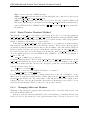
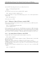
In figure 3.1, page 19 one can see an example with CAMAC computer boards (CVC). The VSB
is the branch. The board is fully equipped with a 68030 processor, ethernet, SCSI and VSB.
18
Version 4.3 October 28, 2003
Performance Measurements
Several different subsystems may be connected to the VSB, i.e. other CAMAC crates with CVCs
or Fastbus crates with Aleph Event Builders (AEB) or LeCroy’s Segment Manager Interconnect
(SMI). The standard software version assumes that each readout processor is triggered by a GSI
trigger module.
3.2.2
One VME Branch
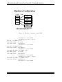
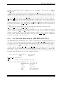
Figure 3.2, page 20 shows an example of a VME based setup. The VME bus is the branch. The
MBS is running on ELTEC VME CPU boards (E6, E7) under Lynx. (see also figure 6.1)
Hardware Configuration
Ethernet
Fastbus
AEB Slave
CAMAC
CVC Slave
VSB
CAMAC
T
r
i
g
g
e
r
CBV
CAMAC
CVC Master
SCSI
CBV: CAMAC VSB interface
CVC: CAMAC VSB Computer
AEB: Aleph Event Builder
Figure 3.1: Hardware Configuration with CVC
3.3
Performance Measurements
There are some measurements of the performance of the system on different hardware configurations. Note that we used a fixed pulser and a conversion time of zero. The numbers represent
therefore the absolute maximum one will not achieve in real life.
Data Transfer VSB to CVC (CAMAC 68030):
Distance 1 m : 2.7 MB/sec, 15 m : 2.4 MB/sec
One CVC, one CAMAC crate:
One word events :
2.2 KHz
700 word events :
900 KB/sec
Version 4.3 October 28, 2003
19
GSI Multi-Branch System User Manual: Command Interface
Hardware Configuration
VME
VSB
Fastbus
E7 Master
SMI
E7 Slave
E7 Slave
CAMAC
E7 Slave
CAMAC
E7 Slave
CBV
CBV
T
r
i
g
g
e
r
CAMAC
CBV
SMI: Segment Manager Interconnect
CBV: CAMAC VSB interface
Figure 3.2: Hardware Configuration with VME
600 KB/sec to tape
240 KB/sec via TCP
One CVC, one CAMAC slave:
One word events :
8.3 KHz
500 word events : 1230 KB/sec
760 KB/sec to tape
One CVC, two CAMAC slaves:
1000 word events : 1400 KB/sec
800 KB/sec to tape
One ELTEC E7 (VME), one CAMAC slave:
One word events : 13.4 KHz
500 word events : 1140 KB/sec
1130 KB/sec to tape
480 KB/sec via TCP
One ELTEC E7 (VME), two CAMAC slaves:
1000 word events : 2040 KB/sec
1230 KB/sec to tape
20
(TZ87)
to client
(TZ87)
(TZ87)
(TZ87)
to client
(TZ87)
Version 4.3 October 28, 2003
Local Environment
Chapter 4
Command Interface
GMC MBS COMIN
The MBS command interface runs on Lynx, AIX, HP-UX, DECunix, and OpenVMS. Dispatcher
and message logger run only on Lynx and DECunix.
4.1
Local Environment
In a local environment (see figure 4.1, page 22) a dispatcher accepts terminal input, forks tasks,
and dispatches commands to these tasks. It is started by alias mbs. It starts a local message
logger. All tasks send their output to this message logger which in term writes them to the log-file
mbslog.l and/or to the terminal. In the following we give a short summary of most often used
commands to control the tasks.
START TASK
STOP TASK
SHOW TASK
SHOW COMMAND
QUIT
Tasks can be stopped in two ways. The softest way is STOP TASK <name>. Then the task
executes the command EXIT and terminates. A harder stop is to kill known tasks by STOP TASK
<name> -KILL and unknown tasks by STOP TASK PID=<pid> -KILL. Then the dispatcher kills
the tasks sending the SIGTERM signal the same way as the Lynx command kill <pid> does.
With qualifier -ALL all known tasks are stopped. Qualifier -ZOMBIE is useful if tasks terminated
abnormally and are in Z status as shown by Lynx command ps -axnt (see also 5.5, page 38).
4.2
Line Input
A command line is composed by command keywords followed by arguments separated by spaces.
All command input except strings enclosed in ”” or beginning with a slash is changed
Version 4.3 October 28, 2003
21
GSI Multi-Branch System User Manual: Command Interface
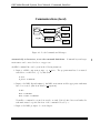
Communications (local)
SBS>
Task
Command
Dispatcher
Task
Log File
Message
Logger
Task
Figure 4.1: Local Commands and Messages
automatically to lowercase, as are the command definitions. Command keys and argument names can be entered in lower or upper case.
An MBS command line can be given in the following situations:
1. Input to a MBS component prompt, e.g. m util>. The program must have been started
stand-alone on shell level, e.g. by alias util.
$ util
m_util> <command>
2. Input to the MBS dispatcher(mbs>). An MBS environment and the appropriate task must
have been created. (mbs is an alias for m dispatch).
$ mbs
mbs> <command>
mbs> <task> <command>
Normally a command is executed in exactly one task. If it is defined in several tasks, the
task name must be specified in front of the command followed by >.
3. Input to the MBS prompter. See next chapter.
22
Version 4.3 October 28, 2003
Local Environment
4. In the shell. The MBS command must be preceded by the alias of the component, e.g.
util or mbs. The first case is equivalent to (1), the second to (2). It is possible to use shell
variables in the command line.
$ util <command>
$ mbs <command>
$ send <node> <command>
4.3
! execute one utility command
! Excute one MBS command
! Excute one (remote) MBS command
Arguments and Qualifiers
The arguments can be written as positional values or by name reference. All keywords may be
abbreviated. Required arguments are prompted.
Positional arguments are delimited by spaces. String arguments containing delimiters must be
enclosed in quotes (”string”). Integer arguments can be entered in decimal, hexadecimal (0xn),
octal (On), or bit (Bn) format. The arguments have names and may be specified in any order by
name=value. The names are found in the help description of the command. A ?? gives a list of
commands and ??? gives a list of commands with arguments. A command with ? as argument
gives the argument definition of the command.
Qualifiers are preceded by a space and a hyphen (-qualifier). They cannot specifiy a value.
4.4
Command Procedures
Command files are called by @. Extension .scom is assumed if only the name is specified. Command files may be nested. A backslash after the filename outputs the lines during execution.
Arguments separated by spaces may be passed to command files. In the files, placeholders $1 ..
$8 are replaced by the arguments. Strings \$ are replaced by $ without replacement. Strings
\\ are replaced by \. In this case a following placeholder will be replaced. All text behind # is
ignored, except # is inside "".
$ mbs @<file>
$ util @<file>\
mbs> @<file> <par1> <par2>
4.5
Defaults
There is currently no default mechanism exept in the action routines!
Version 4.3 October 28, 2003
23
GSI Multi-Branch System User Manual: Command Interface
4.6
Log File
As mentioned already most messages of MBS are written into a log file mbslog.l on the current
directory. In the log file, each message is written together with the date, the time, and the node
name. The log file is opened for append and closed for each message. Different kinds of messages
are marked in the log file by one character between time and node name, i.e. + for commands,
# for informations, and ! for error messages. An example of a log file looks like:
12-Apr-95 13:38:46!CVC40 :dispatch :Command "set task -res" finished with error
12-Apr-95 13:40:26+CVC40 :event_ser:exit
12-Apr-95 13:40:42#CVC40 :stream_se:task m_stream_serv started
24
Version 4.3 October 28, 2003
Remote Environment
4.7
4.7.1
Remote Environment
Prompter
In remote environments (see figure 4.2, page 27) there are also dispatchers and message loggers,
one on each node. These dispatchers are started remotely by the prompter. The prompter is
started by alias prm. There are several ways to specify the nodes the prompter shall connect to.
prm
prm
prm
prm
prm
prm
-r <node>
[-r <node>]
[-r <node>]
[-r <node>]
[-r <node>]
-n
-n
-l
-f
#
#
#
<node>
#
#
<filename> #
nodes from file node_list.txt
get input from send command from node.
no node at all
one node
local node
nodes from specified file
The prompter starts the dispatchers, as well as a local message server. It then connects to the
dispatchers. The remote dispatchers start their message loggers as clients which connect to this
message server via TCP. All commands are sent by the prompter to the destination dispatcher
and then to the destination task. A task sends output to its local message logger which sends it
to the message server where it is printed or logged into the log file.
4.7.2
Additional Prompter Features
The prompter changes its prompt string always to the node name of the default dispatcher, i.e.
$ prm
-CVC40:prompt
:connected to dispatcher
CVC40> SET DISPATCHER CVC38
CVC38> SHO DISPATCHER
-CVC40 :prompt
:connected dispatchers:
-CVC40 :prompt
: 0
CVC40 pid =
-CVC40 :prompt
: 0
CVC38 pid =
-CVC40 :prompt
:Current set dispatcher
CVC40, pid x
26
30
is CVC38
The default dispatcher is changed by command SET DISPATCHER. The prompter sends the commands to the default dispatcher. To send it to a different one, prefix it by <node>::. By prefix
*:: the command is sent to all connected dispatchers.
CVC40> CVC39::<command>
CVC40> *::<command>
The prompter can be left any time by QUIT and started again. All tasks continue to run. All
output from the tasks still appears on the terminal. It is therefore not recommended to enter
any editor. When starting the prompter in a running environment, it connects to all dispatchers
Version 4.3 October 28, 2003
25
GSI Multi-Branch System User Manual: Command Interface
specified. This may take some time. When the remote nodes should be hanging, the command
REMOTE RESET -ALL will cleanup all nodes, i.e. kill all MBS tasks, create new message queues,
and clear the DAQ status table. The command does not cleanup the local node, because the
local message logger may get still messages. To cleanup everything, one leaves the prompter and
uses shell command remote reset. This command accepts either a node name or @file for the
nodes to be cleaned up. See 5.5.4, page 39. Prompter commands:
CONNECT DISPATCHER
DISCONNECT DISPATCHER
SET DISPATCHER
SHOW DISPATCHER
REMOTE RESET
REMOTE SHOW
QUIT
The DISCONNECT command optionally kills the dispatcher (-KILL). The REMOTE RESET command
kills all MBS tasks on specified nodes except the local node. Message files and DAQ status are
reset. Example:
$ prm
CVC40> <command>
CVC40> CVC39::<command>
CVC40> *::<command>
CVC40> CONNECT DISPATCHER CVC38
CVC40> SET DISPATCHER CVC38
CVC38> SHO DISPATCHER
-CVC40 :prompt
:connected dispatchers:
-CVC40 :prompt
: 0
CVC40 pid = 26
-CVC40 :prompt
: 0
CVC38 pid = 30
-CVC40 :prompt
:Current set dispatcher is CVC38
CVC40> DISC DISPATCHER -ALL
prompt> CONNECT DISPATCHER -ALL
CVC38> REMOTE SHOW -ALL
CVC38> *::STOP TASK -ALL
CVC38> REMOTE RESET -ALL
Note that the messages are prefixed by a hyphen, the node name, and the task name (without
leading m ). The STOP TASK -ALL command should be used to shut down all tasks if possible. It
does not stop the remote dispatchers nor message loggers. Therefore one can immediately continue
calling the startup procedure. After REMOTE RESET everything starts from scratch which takes
much longer time.
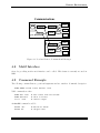
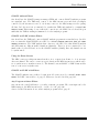
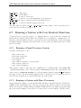
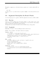
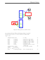
Figure 4.2, page 27 shows how more nodes can be controlled from one terminal through the
prompter.
26
Version 4.3 October 28, 2003
Remote Environment
Communications
Local Node
PRM>
Command
Prompter
Command
Dispatcher
Task
Task
Log File
Message
Client
Message
Server
Command
Dispatcher
Task
Task
Task
Message
Client
Task
Remote Node
Figure 4.2: Local and Remote Commands and Messages
4.8
Motif Interface
On nodes providing motif a motif interface can be called. This feature is currently not used in
MBS.
4.9
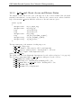
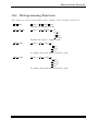
Command Example
The following command has two positional arguments and two switches. Command description:
START EVENT stream events maxclnt -verb
Valid commands are then
START EV 1 1000
START EV max=3
sta ev -verb
# 1000 events from all streams
# allow 3 clients
# verbose output
An invalid command would be
STA EV -abc
STA EV abc
# Switch not known
# illegal value
Version 4.3 October 28, 2003
27
GSI Multi-Branch System User Manual: Running a Data Acquisition
4.10
User Defined Commands
Besides the commands provided by MBS the user may create his own commands and tasks. A
description is found in f cmd.c. An example can be found on VMS in the file
TOOL$examples:m cmd test.c.
28
Version 4.3 October 28, 2003
Prerequisites for MBS
Chapter 5
Running a Data Acquisition
GMC MBS RUN
5.1
Prerequisites for MBS
If you never have used MBS before, some preparations are needed: You must be familiar with
the basic Lynx (UNIX) concepts and commands, and the interrupt handler for CAMAC must be
loaded. This is normally done during the boot process.
5.1.1
Account
Ask the MBS group if your account is sufficiently privileged to run MBS.
5.1.2
Login Procedure
During login the group-specific script /etc/csh.login is executed (for tcsh shell). The directory /etc is in the group tree. In the user-specific .login script, the MBS specific script
/mbs/prodlogin.com must be executed. It sets the default to the production version and defines
alias names (calling /mbs/alias prod.com):
source /mbs/prodlogin.com
news lynx
news daq
One should not include the /bin directories of MBS in the execution pathlist PATH, because all
tasks are called from shell by alias names. With alias deve one executes /mbs/develogin.com
thus switching to the development version. Alias prod again switches back to the production
version by executing /mbs/prodlogin.com. All alias names are redefined accordingly.
Version 4.3 October 28, 2003
29
GSI Multi-Branch System User Manual: Running a Data Acquisition
5.2
5.2.1
To start
1.
2.
3.
4.
5.
5.2.2
Starting MBS
Steps
MBS one must perform the following steps:
Prepare the hardware and the on-line programs for the frontend processors.
Prepare setup file (see 6.3, page 49).
Prepare readout files (see 6.5, page 56) or functions (see 6.6, page 57).
Create an environment (see below).
Start data taking or analyzing.
Setup
The setup profile describes the hardware and software setup. It must be carefully checked. The
parser definition file for the syntax is /mbs/prod/set/setup.pdf.
Examples of user setup files (setup.usf) can be found in the directories in /mbs/prod/exa,
a detailed description in 6.3, page 49 for a single-branch setup and 7.2, page 67 for a multi-layer
setup.
The first action before starting most of the MBS components is to load this setup file, i.e. to
store the values specified in the file into the memory. To do this the m util task must be started:
MBS> START TASK M_UTIL
MBS> LOAD SETUP <setup file>
Next we start the readout tasks, either the master readout on the master crate (where the collector
runs), or the slave readout. Then we load the readout table.
MBS> START TASK m_read_meb # or m_read_cam_slav
MBS> LOAD READOUT <readout file>
Now we have to set up the trigger module. The values are taken from the setup file:
MBS> SET TRIG_MOD
MBS> SHOW TRIG_MOD
5.2.3
Readout
For CAMAC there are two methods to specify the readout: profiles or functions. Other subsystems can only be read by user readout functions. The methods can be choosen for each readout
independently.
CAMAC Readout Profile
The readout profile (CAMAC readout table) describes the readout. The parser definition file
for the syntax is /mbs/prod/set/readout.pdf. Examples can be found in the directories in
/mbs/prod/exa. A detailed description can be found in 6.5, page 56.
30
Version 4.3 October 28, 2003
MBS Readout
Readout by Function
A detailed description of readout functions can be found in 6.6, page 57.
5.2.4
Start Single Environment
Once one has a setup file and a readout table file, one can start up MBS. It is recommended
to have a command procedure, i.e. startup.scom, to start all tasks needed. The following
example shows a startup file for a single-crate system with table readout. The files setup.usf
and readout.mrf must be provided.
start task m_util
load setup setup.usf
set trig_mod
start task m_read_meb
load read readout.mrf
start task m_collector
start task m_transport
# optional tasks
start task m_esone_serv
start task m_histogram
start task m_event_serv
start event -noport
# allow TCP client to connect transport
enable tcp
setup.usf and readout.mrf are file names and may be different. When leaving the dispatcher
by CTRL Z instead of QUIT, all tasks are stopped. This behavior can be used to shut down the
environment. After such a ”hard” shutdown, or after a reboot, one should first cleanup:
inimbs
mbs
mbs> @startup
or
remote reset -local
mbs
mbs> @startup
where startup.scom executes the lines written above.
Version 4.3 October 28, 2003
31
GSI Multi-Branch System User Manual: Running a Data Acquisition
5.2.5
Start Remote Environments
When there are several nodes, environments must be started on each node. The node names
should be in a text file nodelist.txt, one per line. For each environment one should have setup,
redaout and startup files prepared. Then the master startup file (startup.scom) could look like
this:
@startup_local
e7_1::@startup_e7_1
e7_2::@startup_e7_2
e7_3::@startup_e7_3
enable tcp
This procedure must be executed by the prompter. The first command starts the local environment. The next ones execute the startup procedures of the remote nodes.
remote reset
prm
prm> @startup
where startup.scom executes the lines written above.
32
Version 4.3 October 28, 2003
Controling MBS
5.3
Controling MBS
A more detailed description of the commands can be found in the MBS command description
manual.
5.3.1
Acquisition
Control data taking. First some data taking control commands:
MBS> START or STOP or SHOW ACQUISITION
MBS> OPEN or CLOSE FILE
!
! Writing to tape/disk
A START ACQUISITION generates trigger 14 by software. Thus, a user readout function may do
some specific data collection for the first event. Similar, a STOP ACQUISITION generates software
trigger 15. The event with trigger number 15 (last event) is traced through collector and transport
to empty the buffer queues. With remote environments, SHOW ACQUISITION may output different
information depending on the node where it is executed. Some other commands:
SHOW TAPE
TYPE EVENT <events> -VERBOSE
SET FLUSHTIME
SHOW RATE
CLEAR DAQ COUNTER
Tape Handling
The MBS writes the data in ANSI format to tapes or to disk files. Tapes and files are written in
standard GSI format, but in big endian byte ordering. Therefore on OpenVMS byte swapping
must be done (All GOOSY commands provide byte swapping). Writing to tape requires some
additional operations. If the tape is new, it must first be initialized and then mounted. The
initialization and the mount should be done by transport commands.
MBS> INIT TAPE <label>
MBS> MOUNT TAPE <label>
The label of the tape is used for the initialization. After that the tape file will be opened and
started like a disk file.
Note: INIT TAPE deletes all data on the tape! The MOUNT TAPE command may take a long time
when the tape already contains data files, because all files are skipped.
To dismount the tape issue the MBS commands:
MBS> CLOSE FILE
MBS> DISMOUNT TAPE
Version 4.3 October 28, 2003
33
GSI Multi-Branch System User Manual: Running a Data Acquisition
End of Tape
The transport counts the number of buffers and knows the size of the tape. Normally the file is
closed, before the end of tape is reached. When by any reasons the physical end of tape is reached,
the current file is closed and the tape is dismounted. The data acquisition is not stopped.
Tape Errors
When a tape error occurs, the tape is marked as dismounted and the file is marked as closed in
MBS, i.e. no real tape activities are done and the last file remains open. One should remove
the tape immediately from the drive. The last file can be read later up to the end. It is not
recommended to mount such a tape again for writing.
5.3.2
File Output
Writing list mode data from Transport to a file must be explicitly started and stopped by commands. The acquisition can be started and stopped without affecting the file status. The file can
be on disk or on tape. The tape to be used must be initialised and mounted.
When a client, i.e. a GOOSY Transport Manager running under Open VMS, connects via
TCP to the MBS transport task the buffer stream is sent to this client and to tape, except the
TCP channel was enabled by ENABLE TCP -EXCLUSIVE. In this case all data are written to tape
or to the TCP channel. Files may have a specified size and automatic opening of new files is
supported as in GOOSY.
To start file output to a new file and close a file one types
MBS> OPEN FILE <file>
MBS> CLOSE FILE
The CLOSE FILE command does not stop the acquisition.
File Header
The OPEN FILE command writes as first buffer a GSI file header to the file (see 8.2.5, page 80).
The header information can be prompted or read from a text file (see description of OPEN FILE).
File Names
The file
•
•
•
•
34
names must follow some conventions to be usable on both, VMS and UNIX:
Use a...z, 0...9 and underscore .
Do not count on case sensitiveness.
File name extension should be .LMD, where this dot should be the only one.
The length can be up to 16 characters (ANSI file names).
Version 4.3 October 28, 2003
Controling MBS
5.3.3
CAMAC Esone Calls
The utility program m esone provides some commands to execute local CAMAC functions and
to test specific CAMAC modules. The commands are:
camac cnaf <c> <n> <a> <f> <d> <r>
Note that a proper setup file must be loaded, i.e. the same one used for the acquisition! To execute CNAFs from remote nodes, the ESONE module interface provided in GOOSY
can be used. The ESONE server m esone serv must be started. On a GOOSY node, a logical
name CAMAC BRANCH 0 must be defined:
$ DEFINE CAMAC_BRANCH_0 "<node>:ES(<user>)"
where <node> and <user> are specific.
An ESONE library to write ESONE clients is provided. This library is available on VMS,
DECunix, Lynx amd AIX. See 11, page 117.
m esone serv uses on CVC a CAMAC address window different from the readout. Thus X
and Q responses do not interfere. In the setup file there is a parameter ESONE OFF which must be
set to 0x60000 if one wants to use this extra window. When the parameter is set to zero, both,
readout and m esone serv use the same window. On CPUs other than the CVC the parameter
must be always zero. Therefore one should never execute CNAFs on such CPUs when
a readout task is running.
There is another parameter in the setup file which must be set properly to execute CNAFs:
That is PROC ID for each crate. The values are:
1
2
3
4
5
6
7
=
=
=
=
=
=
=
CVC
E6
E7
AEB
CBV
CVI
CAV (Q and X inverted)
Version 4.3 October 28, 2003
35
GSI Multi-Branch System User Manual: Running a Data Acquisition
5.4
5.4.1
On-line Analysis
MBS Histogramming
The MBS provides some tools for simple histogramming. There are commands to handle histograms (CREATE, DELETE, DUMP, SHOW, CLEAR HISTOGRAM). The histograms are allocated in
a shared segment. The segment must be created first by command CREATE MEMORY). Other commands are SHOW MEMORY and DELETE MEMORY.
The user may write an analysis function which is linked with the collector. Templates and
macros to accumulate histograms are provided.
The histograms can be dumped in GSI standard ASCII files and imported into GOOSY or
PAW for further processing. A detailed description is in 10, page 107.
5.4.2
Data Channels from MBS
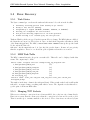
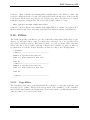
As can be seen in figure 5.1, page 36 there are many channels to get data out of the MBS. The
Connections and Servers
Collector
Transport
Tape/
Disk
Stream
Server
Esone
Server
Event
Server
Master
Node
Remote
Event
Server
TCP
Memory
Esone
Client
GOOSY
TMR
GOOSY
ANL
GOOSY
PAW
Server
PAW
ANL
Figure 5.1: Connections and Servers
GSI standard analysis programs GOOSY and PAW can get events from the event server, the
remote event server, or the GOOSY-PAW server without changes. Which path to use depends
on the requirements concerning the monitoring data rate, the DAQ data rate, and sampling and
filtering. We discuss here some examples:
36
Version 4.3 October 28, 2003
Data Channels
GOOSY without Filters
One should use the GOOSY transport manager TMR and connect GOOSY analysis programs
in a standard way. The TMR may connect to the MBS stream server and then get samples
controlled by the stream server mode. Or it may connect to the MBS transport server getting
all data. In both cases it is recommended to synchronize TMR and analysis by command SET
ACQUIS /SYNC. This setting does not affect the connection to the MBS, but one should keep in
mind that the TMR is waiting in /SYNC mode for the analysis programs.
GOOSY and PAW without Filters
One should use the TMR and connect GOOSY analysis programs in a standard way. In addition one starts the GOOSY-PAW server GPS by commands CREATE PROC GPS $GPS and START
SERVER channel=3. The PAW analysis then connects to the GPS. Note that GOOSY analysis
and GPS must use different mailbox numbers (channels). Therefore it is recommended to use
number three for the GPS and one for the GOOSY analysis (default). But only channel one can
be synchronized!
Using the Event Servers
The MBS event server skips streams when there is no request from clients, i.e. it is an asynchronous channel. The remote event server gets data from the MBS stream server which can be
set to synchronous or asynchronous mode. The channel between GOOSY or PAW clients and the
remote event server is synchronous.
GOOSY and PAW with Filters
The GOOSY analysis can get filtered events from all event servers by command START INPUT
EVENT. For PAW connections see 9, page 87. Filters are described in 9.10, page 101.
Any Program without Filters
One can use the event I/O library to get easily events into programs. The event input can be the
MBS transport, the MBS stream server, or a file. See 9.11, page 106.
A more detailed discussion about on-line analysis programs is in 9, page 87.
Version 4.3 October 28, 2003
37
GSI Multi-Branch System User Manual: Running a Data Acquisition
5.5
5.5.1
Error Recovery
Task States
The Lynx command ps -ax shows the tasks and their states below the S in the headline:
C
R
S
W
B
Z
Currently executing process (will usually be ps itself).
Ready to run, but not running.
Suspended by a signal (SIGSTOP, SIGTSTP, SIGTTIN, or SIGTTOU).
Waiting on a semaphore for some resource.
New process awaiting completion of its fork operation.
Zombie waiting to be cleaned up by the init process.
Tasks are Zombies, if they stopped, but their parent did not cleanup. The MBS tasks are childs of
the dispatcher as long as one did not leave it. Once one has left the dispatcher, all tasks are childs
of the INIT task (ppid=1). The MBS command STOP TASK -ZOMBIE cleans up the specified task
blocks only in the first case.
Otherwise only the INIT task can do it, but only if it gets the chance. It runs on lower priority
than the acquisition. Therefore one should stop the acquisition when there are zombies.
5.5.2
MBS Task Table
The MBS command interface keeps its own task table. This table can be displayed with alias
tasks. The output may look like:
Aktive tasks: read_meb collector transport msg_log dispatch util
3 /mbs/prod/bin_CVC/m_util
(1)
4 /mbs/prod/bin_CVC/m_transport
(1)
5 /mbs/prod/bin_CVC/m_collector
(1)
6 /mbs/prod/bin_CVC/m_read_meb
(1)
36 /mbs/prod/bin_CVC/m_dispatch
(1)
48 test/m_msg_log
(1)
Inactive tasks: event_serv sbs_mon read_cam_slav esone_serv stream_serv
histogram prompt
The number in the first column is the task pid (Lynx). When a task crashed and is still in this
task table, one must cleanup everything with remote reset. The dispatcher reads this table to
get the pids of all known MBS tasks.
5.5.3
Hanging TCP Sockets
When a server having a connection from a client was killed, the socket is not freed immediately.
First it is necessary that the client notices that the connection is broken and closes the socket.
Then it can take up to a minute until the socket is freed. The sockets in use are shown by Lynx
38
Version 4.3 October 28, 2003
Error Recovery
command netstat (see example below). The port numbers used by MBS servers are defined in
/mbs/prod/inc/portnum def.h:
PORT__TRANSPORT
PORT__ESONE_SERV
PORT__STREAM_SERV
PORT__EVENT_SERV
PORT__PROMPT
PORT__MSG_LOG
PORT__PROMPT_R
6000
6001
6002
6003
6004
6005
6006
As long as a socket with one of these port numbers is in state TIME WAIT no server can use this
port number again. This state normally disappears after some time (1 min.).
State FIN WAIT 2 indicates that a client did not close the socket. In this case the socket
remains locked until the client closes the socket. It may take some time until a client gets noticed
that a connection is broken because this happens only when it reads or writes from/to the socket.
Normally all clients then close the socket, and the socket should change its state to TIME WAIT,
and disappear.
5.5.4
Recovery
It may happen that something hangs up. There are some steps one may perform to restart a
hanging system before rebooting all nodes:
Try in MBS or PRM to kill all tasks by command STOP TASK -ALL. This stops all tasks except
the message loggers and dispatchers.
If that does not work, use shell command remote reset to kill MBS tasks on remote nodes,
cleanup message files and DAQ status (file <file> contains one node name per line). Note that
the shell command must be lowercase:
remote
remote
remote
remote
remote
remote
show
show
show
reset
reset
reset
-local
<node>
@<file>
-local
<node>
@<file>
#
#
#
#
#
#
local node
one node
nodes from file <file>
local node
one node
nodes from file <file>
The command remote reset -local does the same as the following single steps:
1. Use alias tasks to get the IDs of tasks which are still running. Kill them.
2. Use ps command to see if all MBS tasks are gone.
3. Initialize the control and status segment by alias inimbs.
4. Clear the message and command communication by alias msg new.
When there are connections in states other than ESTABLISHED, check if all clients closed their
connections. Then wait until all connections are OK or gone (may take up to a minute). To get
Version 4.3 October 28, 2003
39
GSI Multi-Branch System User Manual: Running a Data Acquisition
the netstat of all nodes, use command remote show @<file> -net. To check if everything is
cleaned up execute remote show -local or remote show @<file> to show MBS tasks, pending
messages, or internet connections in state other than ESTABLISHED. It should look like:
CVC40 goofy (17) remote show -loc
===== Task table without root tasks! =====================================
pid
tid ppid pgrp pri text stack data
time dev
user
S name
2 32767
20
20 17
32
12
16
0.21 ttyp0 goofy
C /bin/ps
20 32767
24
20 17
44
8
52
0.28 ttyp0 goofy
W /bin/sh
24 32767
22
24 17 184
16 104
3.79 ttyp0 goofy
W /bin/tcsh
25 32767
20
20 17
48
12
40
0.10 ttyp0 goofy
W /bin/grep
11524K free, 940K used (in this display)
===== Task table of MBS daqst ============================================
Aktive tasks:
Inactive tasks: read_meb collector transport event_serv msg_log dispatch util
mbs_mon read_cam_slav esone_serv stream_serv histogram prompt
===== Message and command files ==========================================
No pending messages in /dev/msg
No pending messages in /dev/com
===== TCP status =========================================================
Active Internet connections
Proto Recv-Q Send-Q Local Address
Foreign Address
(state)
tcp
0
0 CVC40.gsi.de.telnet
VSCA.gsi.de.2889
ESTABLISHED
==========================================================================
40
Version 4.3 October 28, 2003
Session Example
5.6
Session Example
In the following we show a few examples of MBS sessions. Complete file sets for different hardware
setups can be found on directory /mbs/prod/exa.
5.6.1
Single CAMAC System
Lines beginning with # are comments added here. CVC40> is the shell prompt, mbs> is the MBS
prompt, output from MBS starts with -CVC40. All other lines are output from shell commands.
Besides that it is the output of a running system, but it is not ment to be replayed.
CVC40>
# Initialize:
CVC40> inimbs
created and initalized daq status segment
# Clear communication paths:
CVC40> msg_new
message file /dev/msg removed
command file /dev/com removed
Creating new message file /dev/msg
Creating new command file /dev/com
# start mbs:
CVC40> mbs
mbs> @startup
-CVC40 :msg_log :09-May-95 19:08:15 Message logger running
-CVC40 :util
:task m_util started
-CVC40 :util
:setup file setup.usf successfully loaded
-CVC40 :read_meb :task m_read_meb started
-CVC40 :read_meb :load master readout file: read.mrf
-CVC40 :read_meb :trigger:-1
setup_file:init.urf
-CVC40 :read_meb :trigger: 1
setup_file:read.urf
-CVC40 :read_meb :trigger:14
setup_file:read14.urf
-CVC40 :read_meb :trigger:15
setup_file:read15.urf
-CVC40 :read_meb :CNAF table successfully loaded
-CVC40 :collector:task m_collector started
-CVC40 :transport:task m_transport started
# event server was not started in command file:
mbs> sta t m_event_serv
-CVC40 :event_ser:task m_event_serv started. Enable by START EVENT_SERV.
mbs> sta event
-CVC40 :event_ser:Using fixed port 6003
-CVC40 :event_ser:Setup: Buf_str:1/1 M_evt_pstr:ALL/str M_cl:3 Reg_ser:OFF
Version 4.3 October 28, 2003
41
GSI Multi-Branch System User Manual: Running a Data Acquisition
-CVC40 :event_ser:Server created: HOST:CVC40 PORT:6003
mbs> sta ac
-CVC40 :util
:start acquisition
-CVC40 :read_meb :found trig type 14 == start acquisition
-CVC40 :read_meb :READ cnaf: 0x80004000 data: 0x2468
-CVC40 :collector:acquisition running
mbs> sho ac
-CVC40 :util
:--------------------------------------------------------------CVC40 :util
:ACQUISITION STATUS at 09-May-95 19:09:02: active tasks:
-CVC40 :util
:m_read_meb m_util m_msg_log m_collector m_transport
-CVC40 :util
:m_event_serv m_dispatch
-CVC40 :util
:Status INITIALIZED, setup LOADED from setup.usf.
-CVC40 :util
:Readout table LOADED from read.mrf, acquisition RUNNING.
-CVC40 :util
:There are 16 streams with 2 buffers a 4096 [b] each.
-CVC40 :util
:Current crate is 0, event builder is CVC.
-CVC40 :util
:--------------------------------------------------------------CVC40 :util
:Crate
0: ID=
10, LOCAL
SYNC CVC , subevent slots= 500.
-CVC40 :util
: trig 1: cvt= 20, fclrt= 10 [usec], max se length=
812 b
-CVC40 :util
: trig 14: cvt= 20, fclrt= 10 [usec], max se length=
16 b
-CVC40 :util
: trig 15: cvt= 20, fclrt= 10 [usec], max se length=
16 b
-CVC40 :util
:--------------------------------------------------------------CVC40 :util
:Event server delivered 0 events = 0.000 [Mb]
-CVC40 :util
:Histogramming DISABLED
-CVC40 :util
:Name of output device =
-CVC40 :util
:Label = , CLOSED, file = , CLOSED
-CVC40 :util
:
0.000 [MB] written to tape,
0.000 to file
-CVC40 :util
:--------------------------------------------------------------CVC40 :util
:Collected:
2.3142 MB,
565 Buffers,
2545 Events.
-CVC40 :util
:Rate
:
566 KB/s,
138 Buffers/s,
625 Events/s
-CVC40 :util
:-------------------------------------------------------------mbs> ty ev
-CVC40 :transport:===== Buffer
1 =========== 09-May-95 19:09:08.66
-CVC40 :transport:Type= 10
1, Data=2024, Used=2024, Evts= 5, Buf= 1295
-CVC40 :transport:First frag. =0, Last frag.=1, endian=1, Last ev. length= 410
-CVC40 :transport:Event=
5825, Type= 10
1, Words= 410, Trigger= 1
-CVC40 :transport:
SubEv id= 10, Type= 10
1, Words= 402, Subcrate= 0
mbs>
mbs> enab tcp
-CVC40 :transport:starting server thread
-CVC40 :transport:m_transport: wait for connect, port number = 6000
# now a client connects to transport:
-CVC40 :transport:server thread: connected
42
Version 4.3 October 28, 2003
Session Example
# and disconnects (all four messages):
-CVC40 :transport:pipe broken, disconnecting
-CVC40 :transport:closed tcp connection
-CVC40 :transport:ERROR: stc_write
-CVC40 :transport:closed tcp connection
# now a client connects to event server:
-CVC40 :event_ser:I-f_ev_acc_clnt-INFO: Client no:1 accepted.
# and disconnects:
-CVC40 :event_ser:I-f_ev_rmclnt-INFO: client no:1 removed.
# start stream server (stop event server first)
mbs> stop task m_event_serv
-CVC40 :event_ser:/mbs/deve/bin_CVC/m_event_serv exiting.
mbs> sta task m_stream_serv
mbs>
-CVC40 :stream_se:task m_stream_serv started
mbs>
mbs> quit
CVC40> tasks
Aktive tasks: read_meb collector transport msg_log util stream_serv
4 /mbs/deve/bin_CVC/m_read_meb
(1)
5 /mbs/deve/bin_CVC/m_util
(1)
6 /mbs/deve/bin_CVC/m_msg_log
(1)
7 /mbs/deve/bin_CVC/m_collector
(1)
8 /mbs/deve/bin_CVC/m_transport
(1)
10 /mbs/deve/bin_CVC/m_stream_serv
(1)
Inactive tasks: event_serv dispatch mbs_mon read_cam_slav esone_serv
histogram prompt
CVC40> rate -t1
Interval: 1 s. 2 buffers a 4096 b per stream.
109622 Bufs,
493301 Evts,
109768 Bufs,
493961 Evts,
109911 Bufs,
494602 Evts,
110050 Bufs,
495227 Evts,
^C
CVC40> mbs
mbs> sho task
-CVC40 :dispatch :Task table of
-CVC40 :dispatch : m_read_meb
Version 4.3 October 28, 2003
0.
143
139
136
Bufs/s,
Bufs/s,
Bufs/s,
Bufs/s,
0.
586
569
558
KB/s,
KB/s,
KB/s,
KB/s,
0.
647
622
613
Evts/s
Evts/s
Evts/s
Evts/s
MBS:
/mbs/deve/bin_CVC/m_read_meb
id 4 (4)
43
GSI Multi-Branch System User Manual: Running a Data Acquisition
-CVC40 :dispatch : m_util
/mbs/deve/bin_CVC/m_util
id 5 (5)
-CVC40 :dispatch : m_msg_log
/mbs/deve/bin_CVC/m_msg_log
id 6 (-1)
-CVC40 :dispatch : m_collector
/mbs/deve/bin_CVC/m_collector
id 7 (7)
-CVC40 :dispatch : m_transport
/mbs/deve/bin_CVC/m_transport
id 8 (8)
-CVC40 :dispatch : m_stream_serv /mbs/deve/bin_CVC/m_stream_serv
id 10 (10)
-CVC40 :dispatch : m_dispatch
/mbs/deve/bin_CVC/m_dispatch
id 16 (16)
-CVC40 :dispatch :Task table of dispatcher:
-CVC40 :dispatch : m_dispatch
started
-CVC40 :dispatch : m_read_meb
started
-CVC40 :dispatch : m_collector
started
-CVC40 :dispatch : m_util
started
-CVC40 :dispatch : m_transport
started
-CVC40 :dispatch : m_stream_serv started
-CVC40 :dispatch : m_msg_log
detached
-CVC40 :dispatch :Get full commands by ?? or ??? or get arguments by <command> ?
#
# Now shut down
#
mbs> stop ac
-CVC40 :util
:stop acquisition
-CVC40 :read_meb :found trig type 15 == stop acquisition
-CVC40 :collector:acquisition NOT running
mbs> stop task -all
-CVC40 :read_meb :/mbs/deve/bin_CVC/m_read_meb exiting..
-CVC40 :collector:/mbs/deve/bin_CVC/m_collector exiting..
-CVC40 :transport:/mbs/deve/bin_CVC/m_transport exiting
-CVC40 :util
:/mbs/deve/bin_CVC/m_util exiting..
# stop m_stream_serv:
mbs> stop t m_stream_serv
-CVC40 :stream_se:/mbs/deve/bin_CVC/m_stream_serv exiting
mbs> quit
# kill message logger (task id from above)
CVC40> kill 6
# check if all tasks are gone:
CVC40> tasks
Aktive tasks:
Inactive tasks: read_meb collector transport event_serv msg_log dispatch util
mbs_mon read_cam_slav esone_serv stream_serv histogram prompt
# Clear communication paths:
CVC40> msg_new
message file /dev/msg removed
command file /dev/com removed
44
Version 4.3 October 28, 2003
Session Example
Creating new message file /dev/msg
Creating new command file /dev/com
# Initialize:
CVC40> inimbs
created and initalized daq status segment
CVC40>
CVC40>
Version 4.3 October 28, 2003
45
GSI Multi-Branch System User Manual: Readout Control
46
Version 4.3 October 28, 2003
Readout Tasks
Chapter 6
Readout Control
GMC MBS READ
6.1
Readout Tasks
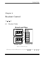
Branch and Pipes
Pipecontrol
Buffer
Branch
Window
1
2
Pipecontrol
Buffer
Readout Tasks
15
Collector Task
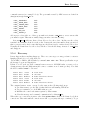
Figure 6.1: Branch and Pipes
All hardware modules in a MBS system are read by the tasks m read meb and/or m read cam slav
Version 4.3 October 28, 2003
47
GSI Multi-Branch System User Manual: Readout Control
and/or m read aeb slave.
The m read meb task runs on the branch master controller and reads possibly its local and/or
its remote crates equipped with non intelligent controllers (CAMAC: CBV, FASTBUS: SMI).
m read meb runs on the CVC (CAMAC), E6 and E7 (VME). m read cam slav runs only on CVCs
acting as intelligent CAMAC slave controllers and it reads only its local crate. m read aeb slave
runs only on AEBs acting as intelligent FASTBUS slave controllers and it reads only its local
crate.
All readout tasks decribed above write their data into subevent pipes. For each crate a
subevent with a GSI subevent header is written into the pipe(s). The subevent pipes may reside
locally in the controller memory but they could also be placed into a remote memory module
which is accessable in an address mapped mode. The pipes are read, formatted into events into
GSI buffers by the collector task which runs on the branch master.
All readout tasks need a corresponding GSI trigger module to start the (event) readout.
m read meb may be triggered in an interrupt or in a polling mode. If polling mode is selected
the trigger module must not necessarly be placed in the same crate. It can be anywhere, where
m read meb has address mapped access to its trigger module registers. In interrupt mode it must
be in its local crate.
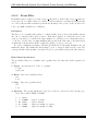
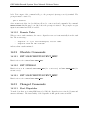
m read cam slav and m read aeb slav are always triggered in polling mode. The trigger
module must therefore be in the local crate.
Two methods of readout specification are provided. If the hardware modules to be read out
are pure CAMAC the readout can be specified in simple readout tables. The readout itself is
then performed with zero suppression. Generally the user may write user readout functions to
read out any type of module in any type of crate. No mixture between table readout and user
readout function is possible.
A complete single-branch system (and single-crate) setup must be specified in a single ASCII
file.
6.2
Readout Software Overview
Specification of the hard and software configuration of a single-crate or single-branch data acquisition system is kept in a single ASCII file provided by the user. It has the name extension .usf,
which stands for ”user setup file”. A convenient name is setup.usf.
The system is furthermore specified by running the appropiate tasks, especially the readout task, on the intelligent controllers. This will be done in startup command procedures
(”start.scom”) at system startup. On the branch master controller the task m read meb has to
be started, but only if any crate has to be read out by it. On CVCs working as slave controllers
the task m read cam slav and on AEB-EBIs m read aeb slave must be started.
Two methods for specifying the readout of hardware modules are provided. The easy but
less versatile method uses user written readout tables (ASCII files), which must be loaded by
command. This method is only possible for systems with pure CAMAC readout. The second
method provides an interface for users to write their own readout function in the program language
48
Version 4.3 October 28, 2003
Single-Branch Setup Specification
Buffer Streams
Collector
Buffer
Buffer
Buffer
Buffer
Stream
Transport
Eventserver/
Streamserver
Figure 6.2: Buffers and Streams
C. There is practically no limitation on actions in this functions, so the user gets the full flexibilty
but also the full responsibility for a correct working readout. No mixture between these two
methods inside a single branch is allowed. In both methods a crate corresponds to a subevent,
which means that the readout tasks produce a subevent for each crate with an appropriate
subevent header.
6.3
Single-Branch Setup Specification
As mentioned above the system specification is done in an ASCII file. This file (setup.usf) will
be parsed, checked and the setup quantities loaded into each controller (processor) memory at
an early stage of system startup. All running tasks access this memory module to get the system
configuration information.
The best way to produce a setup file ist to copy a template file and change all entries according
to the following explanations. In the directory /mbs/prod/exa several subdirectories will be
found, which contain complete working environments for various data acquistion setups. Each of
them contains a valid setup.usf file. The names of these directories describe already the kind
of setup.
The following description will follow the sequence in the template files. All values for parameters not mentioned should not be changed. For more information on those see s setup.h on
/mbs/prod/inc/. Behind each parameter in the user setup file follows a number which could
also be an array of numbers, where the index of the array indicates (up to now) always the crate
number.
NOTE: If a parameter requires an array of numbers (for crate 0-15), values for all array
elements must be specified, regardless if a crate is used or not. This is required by the parser
Version 4.3 October 28, 2003
49
GSI Multi-Branch System User Manual: Readout Control
syntax.
All these values are meaningless as long as the values given for the Readout Flag parameter
RD FLG - which one can think of as the master flag - are zero. Valid values for the RD FLG parameter
as a function of the crate number are:
0 : Nothing should be done with this crate.
1 : The branch master must read out this crate.
2 : A local intelligent controller reads this crate.
6.3.1
Setup File: Parameters
The syntax is found in 8.1.1, page 74. Now follows the explanation of the relevant parameters in
the setup file:
MASTER : Indicates the type of the branch master:
1 : CVC
2 : E6
3 : E7
REM MEM BASE : (array) Physical base address for a shared segment inside a remote
subevent pipe will be seen by the branch master. On VSB systems this must be 0xF0000000
for E6 and E7 and 0x08000000 for a CVC as branch master.
REM MEM OFF : (array) Offset to a shared segment. On VSB based systems this must be
crate nr. * 0x200000. REM MEM BASE + REM MEM OFF define the physical start address of a
remote subevent pipe.
REM MEM LEN : (array) Length of a shared segment with physical base REM MEM BASE +
REM MEM OFF and therefore length of the remote pipe (in bytes).
The memory on the CVC can be accessed via VSB only from the beginning of the RAM
with base address 0x100000 up to about 500 kB. But normally this is also the base address
of the LynxOS (UNIX) kernel. As a compromise the kernel base address has been moved
to 0x140000, leaving an address window from 0x100000 to 0x140000 free for the subevent
readout pipe. For the AEB-EBI fastbus controller the subevent readout pipe is placed into
the EBI memory with base address 0x1000000 seen from the AEB.
REM CAM BASE : (array) Physical base address to a shared segment for executing remote
CAMAC from the branch master via a CBV. On VSB systems this must be 0xF0180000
for E6 and E7 and 0x08180000 for a CVC as a branch master.
REM CAM OFF : (array) Offset to a shared segment. On VSB based systems this must be
crate nr. * 0x200000. REM CAM BASE + REM CAM OFF define the physcial start address of a
remote CAMAC segment. These base adresses are passed as virtual pointers into the user
readout function.
50
Version 4.3 October 28, 2003
Single-Branch Setup Specification
REM CAM LEN : (array) Length of a shared segment with physical base REM CAM BASE +
REM CAM OFF and therefore length of the remote CAMAC segment. REM MEM LEN = 0x50000
is enough to cover the complete CAMAC space of one remote crate.
LOC ESONE BASE : This setup parameter is used only if the task m esone serv is running
on a branch master CVC. In this case it must be set to 0x4180000.
REM ESONE BASE : This setup parameter specifies the address window to access remote
CAMAC on slave crate controllers connected via VSB from a VSB branch master. The VSB
master could be any processor type. For a CVC this parameter must be set to 0x8180000,
for an E6 and E7 it must be set to 0xf0180000.
ESONE OFF : Principally, CAMAC cnafs can be executed from the m esone serv task at the
same time a readout is running and accessing CAMAC. Then the problem arises that it
is not possible to distinguish if CAMAC X and Q belongs to the readout or ESONE cnaf.
This problem has been circumvented only on CVCs, regardless if VSB master or slave, by
implementing a second CAMAC address window reserved for ESONE cnafs. This window
is placed 0x50000 above the normal readout window and this is the value for this parameter.
It implies that ESONE cnafs should not be executed on E6 or E7 (master) and CBVs (slave)
when a readout is running.
Note: The parameter CONTROLLER ID described below must also be set to the right value
to get correct X and Q from ESONE calls.
LOC MEM BASE : (array) These are the hardware base adresses where each intelligent controller in a single branch is supposed to access its hardware modules. It could be for example
the local CAMAC base or the extended VME base. This base address is passed as a virtual
pointer into the user readout function.
LOC MEM LEN : (array) Length of the address window, with base LOC MEM BASE.
LOC PIPE BASE : (array) Parameter to specify the base address of a shared segment inside
the subevent pipe will be placed. Must be specified for each intelligent controller in a single
branch. This parameter is always the local address on a controller.
PIPE OFF : (array) The start address of a subevent pipe is specified with LOC PIPE BASE +
PIPE OFF.
PIPE SEG LEN : (array) Total length of the subevent pipe on each intelligent controller (in
bytes).
PIPE LEN : (array) Maximum number of subevents which can be stored in a subevent pipe
before the pipe blocks.
The structure of the subevent readout pipe is fully specified by PIPE SEG LEN and PIPE LEN:
The first 20 bytes at the beginning of the pipe are reserved for a general pipe control
structure. Then follow PIPE LEN subevent control structures, 20 bytes each. The remaining
Version 4.3 October 28, 2003
51
GSI Multi-Branch System User Manual: Readout Control
space is divided into two longword aligned data buffers. The values for PIPE SEG LEN
and PIPE LEN should be specified so that on average the data for PIPE LEN subevents fit
into the two data buffers. Note that subevents cannot span over buffer boundaries. It
must be ensured that the largest subevent is not bigger than the size of one data buffer,
i.e. (PIPE SEG LEN - 20 * (PIPE LEN + 1)) / 2. The subevent data in the pipe buffers
includes the subevent header(s).
MAX SE LEN TRIGTYP1 ... MAX SE LEN TRIGTYP15 : (arrays) These 15 parameters are optional and must ONLY be specified if user readout functions are used as
readout method. For table readout they can be ommited. They specify the maximum
size of a subevent in number of bytes as a function of crate number and trigger type.
For each trigger type which possibly will be fed into the trigger module the appropriate
MAX SE LEN TRIGTYPX must be found in the setup file.
RD FLG : (array)
0 : Crate shall not be read,
1 : Crate shall be read by master event builder,
2 : Crate shall be read by slave controller
RD TYP : Readout method:
0 : table readout (CAMAC only)
1 : user readout functions
CONTROLLER ID : (array) Type of crate controller:
1 : CVC
2 : E6
3 : E7
4 : AEB-EBI
5 : CBV
6 : CVI
7 : CAV
A correct CONTROLLER ID is also required by the esone server task running on the branch
master.
SY ASY FLG : (array) Each crate (subevent) can be set as a synchronous or an asynchronous
crate. Synchronous means that the collector will wait for this subevent to be ready. Asynchronous means that the subevent will be ignored if it was not ready at the time the
collector task is scanning to build the event. SY ASY FLG = 0 synchronous, SY ASY FLG = 1
asynchronous.
COL MODE : Specifies the output mode of the collector task running on the branch master.
0 : (Standard mode) the collector collects subevents from the various subevent pipes and
formats events into buffer streams and passes the streams to the transport task.
1 : The collector collects subevents from the various subevent pipes but no event formatting
52
Version 4.3 October 28, 2003
Single-Branch Setup Specification
will be done. Instead all collected subevents are written into a single output pipe. This
output pipe will itself be read by a collector of a higher layer in a multi-layer multi-branch
system. This mode requires that ML PIPE BASE ADDR, ML PIPE SEG LEN and ML PIPE LEN
to be specified (see explanation below).
2 : If a single-branch system consists of only one intelligent processor and is itself a component of a multi-layer multi-branch system it can be very useful that no collector task runs
at all in this single branch. The subevents are written by the m read meb task into the
subevent pipe, which is read by a next layer collector.
3 : this mode includes mode 0 and 1. It makes it possible to pass data to output devices
on any node with a running collector.
ML PIPE BASE ADDR : Base address of a collector output pipe. Only requested if COL MODE
is either 1 or 3.
ML PIPE SEG LEN : Length of the collector output pipe (in bytes). Only requested if
COL MODE is either 1 or 3.
ML PIPE LEN : Number of subevent/fragment slots of the collector output pipe. Only requested if COL MODE is either 1 or 3.
NOTE: The structure of the collector output pipe is actually the same as the subevent
pipes written by the readout tasks. The collector scans for all pipes it has to read and
writes all subevents consecutively into the output pipe.
COL RETRY : Number of scans for ready pipes the collector task performs before giving other
tasks the chance to execute by system call yield.
MEB TRIG MODE : This parameter can be used to specify special modes for the trigger
module serving the m read meb task. Modes are:
0 (standard) = local interrupt (CAMAC LAM, VME irq).
For the next special modes the setup parameters SPECIAL MEB TRIG BASE and
SPECIAL MEB TRIG TYPE described below must specify the base address and trigger module
type, respectively.
1 (special) = local interrupt (CAMAC LAM, VME irq), but non-standard base address of
the triggermodule.
2 (special) = remote VSB interrupt, i.e. trigger module is not located inside the local crate
(not yet implemented).
3 (special) = no interrupt, but polling mode. In this mode the readout task polls a bit in
the trigger status register. No other task can execute until the Lynx time slice is over and
the scheduler switches execution to another task.
In all modes the fast clear and conversion time will be taken from parameters TRIG FCT[0]
and TRIG CVT[0].
Version 4.3 October 28, 2003
53
GSI Multi-Branch System User Manual: Readout Control
SPECIAL MEB TRIG TYPE : Must be specified when MEB TRIG MODE is not set to zero.
1 : CAMAC trigger module
2 : VME trigger module
3 : FASTBUS trigger module
SPECIAL MEB TRIG BASE : Must be specified when MEB TRIG MODE is not set to zero.
NOTE: If the trigger module is in a remote (VSB) CAMAC crate, the CAMAC VSB base
address must be specified. For example 0xF0580000 for a CAMAC trigger module in crate
2 serving m read meb running on an E7 in a VME crate.
TRIG STAT NR : (array) Station number of trigger module. Set always to 1 and in CAMAC
crates it must be housed in station number 1.
TRIG FCT : (array) Fast clear time for trigger modules. The number specified has to be in
the range of 20-65535 and must be smaller than TRIG CVT. The fast clear time is set to: 100
nanoseconds * TRIG FCT.
TRIG CVT : (array) Trigger conversion time. The number specified has to be in the range of
20-65535. The conversion time is set to: 100 nanoseconds * TRIG CVT.
The range for TRIG FCT and TRIG CVT is between 2 µsec and 6.5 msec. Both numbers are
written into the trigger module during initialisation with the command set trig mod.
Immediatly after a trigger signal is detected by a trigger module the conversion time is
started. After it has elapsed a LAM/IRQ is sent into the crate controller and the readout
procedure is started. The conversion time is intended to allow for conversion and digitization
of hardware modules and adds deadtime.
Therefore the conversion time must be set to the maximum time required for all modules to
be read by the task serving that trigger. I.e. in case the trigger module triggers the readout
task on the branch master (m read meb, crate number = 0) the conversion time must be set
to the maximum time required for any module in all crates to be read by m read meb.
A time delay between the arrival of an interrupt and the first readout action executed by
the readout task of at least 140 µs on a CVC and 40 µs on an E7 has been measured.
This delay was found for the master readout task (m read meb) working in interrupt mode.
It operates in a multitasking environment and the delay is the time the operating system
needs to inform a user task on an external interrupt. On a CVC working as a slave controller
the delay is much smaller, since in this case the mechanism to catch triggers is polling, which
is much faster (shorter than 5 µs).
On CAMAC CVC single-crate systems, the user therefore can save deadtime by taking
the interrupt delay into account calculating the conversion time. I.e. if the needed real
conversion time is smaller than 140 µs the trigger conversion time may be set to the minimum
value of 2 µs (TRIG CVT = 20).
EV BUF LEN : Length in bytes of one buffer, multiples of 1024 up to 32768 are allowed.
54
Version 4.3 October 28, 2003
Readout Specification
N EV BUF : Number of buffers contained in one stream.
N STREAM : Number of streams.
EV BUF LEN, N EV BUF, and N STREAM have nothing to do with the readout, they are described for completeness. If there are no special requirements a reasonable choice would be:
EV BUF LEN = 0x4000 = 16384, N EV BUF = 8, N STREAM = 8. This specifies an event buffer
space of 8 buffers times 8 streams, thus in total 1 Mbytes of space. If users want to have a
larger event buffer space, it must be checked if that amount of memory is free after all data
acquisition tasks have been started.
For the exact meaning of the remaining parameters one should see 8.2, page 79. The values set for
these will appear in the event and subevent headers and are important for analysis programmes,
but not for the data acquisition itself.
EVT TYP SY : Event type for events. Strongly recommended is EVT TYP SY = 10.
EVT SUBTYP SY : Subevent type for events.
SE TYP (array): Subevent type. For CAMAC crate subevents SE TYP = 10 is recommended.
SE SUBTYP (array): Subevent subtype.
SE CONTROL : This parameter can be used freely by the user, but it is strongly recommended
to put a branch identifier in multi-branch systems at this place to be able to identify branches
in analysis programs.
SE PROCID : Subevent processor identifier which can be set freely by the user.
NOTE: Don’t mix up ”subevent type” and ”event subtype”.
6.4
Readout Specification
Both readout methods, table readout and user readout proceed in the following way: After the
command START ACQUISITION the init function is called which executes actions, but no data will
be moved into the event stream. This is intended for proper initalization of hardware modules.
Then a software trigger with type 14 is send to the trigger module, which starts an event readout
sequence. The first event after START ACQUISITION is always of trigger type 14. After that the
system waits for hardware triggers and for each occurrence an event will be built. The STOP
ACQUISITION command initiates a software trigger of type 15, which also starts a normal event
readout sequence. Thus the last event in the data will always be trigger type 15.
Version 4.3 October 28, 2003
55
GSI Multi-Branch System User Manual: Readout Control
6.5
Table Readout
Syntax see also 8.1.3, page 77. Table readout is only possible in systems which include only
CAMAC modules. It is specified in two steps. First, a master readout file (i.e. read.mrf) which
specifies the filenames for the init (i.e. init.urf) and readout tables (i.e. readxy.urf) must
be provided. Second, the init and readout tables (*.urf files), which define the CAMAC actions
must also be created.
Once the files have been created they can be loaded into shared memory tables with the command LOAD READOUT fn.mrf when the readout task is running. This command can be executed
with different master readout files as many times as the user likes to do. The last loaded, will
come into operation.
6.5.1
Table Readout Parameters
In the master readout file one can specify the following facilities, i.e. lines with a certain syntax
identified by a name (facility). The provided parameters are written in brackets.
INITFILE : file=<>. Specification of init file.
READFILE : file=<>, trigger=<>. Specification of readout files for each trigger.
In the init file one can specify the facility:
CAMINIT : crate=<>, nstation=<>, address=<>, function=<>,
optional data=<> and repetition=<>. CNAF specification.
In the readout file one can specify the facility:
CAMREAD : crate=<>, nstation=<>, address=<>, function=<>,
optional repetition=<>. CNAF specification.
The <> have to be replaced by the appropriate values.
6.5.2
Table Readout Subevents
Table readout performes a zero suppression. For each CNAF resulting a non zero value there are
two 16 bit words in the subevent. The first one is the value, the second one the current number
of the CNAF in the file (big endian!).
6.5.3
Table Readout Example
Example (/mbs/prod/exa/cvc camac single crate table read/read.mrf)
56
Version 4.3 October 28, 2003
Readout Specification
INITFILE:
READFILE:
READFILE:
READFILE:
READFILE:
file="init.urf"
file="read1.urf",
file="read1.urf",
file="read14.urf",
file="read15.urf",
trigger=1
trigger=3
trigger=14
trigger=15
The example shows that for each trigger type a file must be provided, the same files are allowed
for different trigger types. If the init file is not specified this results simply in no action. Also
if trigger types occur during data taking which have no corresponding readout file a subevent
without data will be produced and found in the event. The extensions of the files must be .urf
for User Readout File.
Example (/mbs/prod/exa/cvc camac single crate table read/init.urf)
CAMINIT:
CAMINIT:
CAMINIT:
#
CAMINIT:
CAMINIT:
CAMINIT:
#
CAMINIT:
CAMINIT:
CAMINIT:
c= 0,
c= 0,
c= 0,
n= 30,
n= 2,
n= 2,
a= 9,
a= 0,
a= 0,
f= 24
f= 16, d= 0x2468
f= 0, rep=3
c= 1,
c= 1,
c= 1,
n= 30,
n= 2,
n= 2,
a= 9,
a= 0,
a= 0,
f= 24
f= 16,
f= 0
d= 0x1111
c= 5,
c= 5,
c= 5,
n= 30,
n= 2,
n= 2,
a= 9,
a= 0,
a= 0,
f= 24
f= 16,
f= 0
d= 0x5555
It is good habit to include the CAMAC action shown in the example CAMINIT: c= 0, n= 30,
a= 9, f= 24 for each crate, since this removes the CAMAC inhibit, which is set after power on.
Most commercial modules require this to be accessible on the CAMAC bus. Both, CAMAC read
and write functions are allowed in the init part.
Example (/mbs/prod/exa/cvc camac single crate table read/read1.urf), for trigger type 1.
CAMREAD:
CAMREAD:
CAMREAD:
c= 0,
c= 1,
c= 5,
n= 2,
n= 2,
n= 2,
a= 0,
a= 0,
a= 0,
f= 0,
f= 0,
f= 0,
rep=100
rep=5
rep=1
Due to performance considerations only CAMAC read functions are allowed in the readout part.
In the init and readout files all actions can be put, regardless if the readout will be executed
by a slave controller or the branch master. CAMAC actions (CNAFs) specified for crates not
read out are not loaded if the setup parameter RD FLG is 0 for these crates.
6.6
User Function Readout
There are two different methods to create user readout functions. The first one uses macros to
read out hardware. It is intended for users with no knowlege of the C programming language.
Version 4.3 October 28, 2003
57
GSI Multi-Branch System User Manual: Readout Control
The second method uses static pointers. If the user wants to produce the fastest possible readout
the second method has to be chosen, since the simplicity of the first one is paid by a slightly
lower performance readout. The best way to make a user readout would be to copy a template
directory and make changes in the template f user.c file. In the directory /mbs/prod/exa
several subdirectories will be found, which contain complete working environments for various
data acquistion setups. Each of them contains a valid f user.c file. The names of these directories
describe already the kind of setup. The readout task is then compiled and linked by executing
the ”make” command. The necessary Makefile is also placed in this directory.
NOTE: It is absolutely vital that the maximum subevent size specified in the setup file
(MAX SE LEN TRIGTYP1 ... MAX SE LEN TRIGTYP15) is not exceeded in the user readout function. The f user.c template file contains the functions f user init and f user readout. The
calling is the same for both methods mentioned above.
int f_user_init (unsigned char bh_crate_nr,
long
*pl_loc_hwacc,
long
*pl_rem_cam,
long
*pl_stat)
bh crate nr: Crate number
pl loc hwacc: Base pointer for execution of local crate readout
(master- or slave readout task).
pl rem cam: Array of base pointers for execution of remote CAMAC actions via VSB for
crate number = bh crate nr (master readout task m read meb).
Pointer for status return (not used yet).
pl stat:
f user init is called once for each crate readout after the START ACQUISITION command.
int f_user_readout (unsigned
unsigned
register
register
long
s_veshe
long
long
bh trig typ:
bh crate nr:
pl loc hwacc:
pl rem cam:
58
char
char
long
long
bh_trig_typ,
bh_crate_nr,
*pl_loc_hwacc,
*pl_rem_cam,
*pl_dat,
*ps_veshe,
*l_se_read_len,
*l_read_stat)
Trigger type
Crate number
Base pointer for execution of local crate actions
(master- or slave readout task).
Array of base pointer for execution of remote CAMAC actions via VSB for
crate number = bh crate nr (master readout task).
Version 4.3 October 28, 2003
Readout Specification
pl dat:
ps veshe:
l se read len:
l read stat:
Pointer
Pointer
Pointer
Pointer
where to write data.
to access and manipulate subevent header.
to return total subevent length in bytes.
for status return (not used yet).
For each occurrence of a trigger the f user readout function is called once for each crate.
The same object file compiled from functions f user init and f user readout will be linked
into the master- and slave readout tasks. The data acquisition system takes into account for which
crate number the readout functions are called. The template files show one possible procedure
to distinguish actions for different crate numbers and trigger types with a C ”switch” statement.
This method allows the complete init/readout actions to be kept in a single file, regardless of
crate number, trigger type, master or slave readout task. Similarly, init/readout actions of crates
or trigger types not used for a specific run can be left in the code which saves unnecessary
compilation time.
6.6.1
Macro Readout Method
One may use convenient readout macros in f user init and/or f user readout. Five macros
have been prepared and are found in read mac.h in the
/mbs/prod/exa/cvc camac single crate macro read template directory. Each macro represents a CAMAC action. In macros that write data into the event stream care is already taken
for incrementing the subevent length and the pointer pl dat, were the data has to be written.
The user is free to create further macros.
The syntax and parameters to pass for CAMAC macros are:
CNAF RD INIT(c,n,a,f,offset) : Reads one CAMAC word from a module but writes nothing
into the subevent data.
CNAF RD(c,n,a,f,offset) : Reads one CAMAC word and writes it as a long word into the
subevent data.
CNAF RD 0SUP(c,n,a,f,offset) : Reads one CAMAC word, checks if CAMAC data is zero,
if not writes 16 bit of data into bit 16-31 and an incremented channel number into bits
0-15 of a long word and writes it into the subevent. If the CAMAC data value is 0 only
the channel number is increased. This is actually the same action as implemented for the
standard table readout.
CNAF TOUCH(c,n,a,f,offset) : Dataless CAMAC function.
CNAF WR(c,n,a,f,data,offset) : CAMAC write action.
c = crate number,
n = station number,
a = subaddress,
f = function
Version 4.3 October 28, 2003
59
GSI Multi-Branch System User Manual: Readout Control
data = data to write into CAMAC modules.
offset = pl loc hwacc if crate is the local of the intelligent crate controller were the readout
task runs (m read meb or m read cam slav).
offset = pl rem cam[crate nr.] if crate is not local to the crate controller, which reads
that crate. This can only be the master readout task (m read meb) which reads that remote
crate via VSB and remote CAMAC actions. pl loc hwacc and pl rem cam are passed into
the function.
6.6.2
Static Pointer Readout Method
The structure of the f user.c file must be as following. Before the code of the three functions
f user get virt ptr, f user init and f user readout all hardware addresses (CNAFs, VME)
accessed during the init phase and readout have to be be defined as static volatile (long) pointers.
Arrays or structures of pointers are of course possible.
In the function f ut get virt ptr these pointers have to be constructed as virtual pointers,
that means an offset has to be added to the hardware adresses. The necessary offsets are passed
as parameters with the function and are known only at runtime. The same rules holds like in
the macro method: Crates read out by local intelligent controllers have an offset pl loc hwacc.
For non-local crates read out by the master readout task, the offset is pl rem cam[crate nr.].
To create virtual pointers to acccess CAMAC a macro CNAF is coded in the very beginning of
f user.c. The call
virt ptr = CNAF(c,n,a,f,offset);
creates the virtual pointer for the use in the f user init and f user readout function. In the
f user readout function the user now has to care for the correct incrementing of the pl dat
pointer when writing data into the subevent. A typical operation to read from hardware and
write into the subevent would be
*pl dat++ = *virtual ptr;
At the end the correct subevent length in bytes has to be returned:
*l se read len = length in bytes;
For users familiar with the LynxOS operating system there is also the possibility to create
shared memory segments in any hardware address window in the f user init function with
the smem create library call. The return value of this function would be the virtual pointer
(offset) to the base of the specified hardware adress window. In that way it is possible to access
any address based hardware which is connected to the specific controller.
6.6.3
Changing Subevent Headers
Changing or introducing more (private) subevent headers can be done in the same way for both
user readout function methods.
In front of each subevent data part filled by the readout function, a standard GSI subevent
header is added by the system (see 8.2.9, pagerefdata-subevent). It is up to the user to add
60
Version 4.3 October 28, 2003
Readout Specification
information behind this header by writing at the very beginning of each readout onto pl dat
(*pl dat++).
The structure of this header is found in /mbs/prod/inc/s veshe.h (see 8.2.9, page 83). Some
quantities in the subevent header have been already specified in the setup file, some have to be
calculated at run time like the subevent length. The user gets access to the subevent header with
the pointer ps veshe passed into the f user readout function. If the function writes a value into
ps veshe→l dlen, the system assumes that the user took full control over the subevent header
and does not change it any more. By this method the readout function can overwrite the values
in the subevent header, i.e. type and subtype. If ps veshe→l dlen is not changed, the system
sets it using the parameter l se read len which must be correctly set by the readout function
anyway.
As long as the readout function does not split its data buffer into several subevents
ps veshe→l dlen must be l se read len/2 + 2 if set.
It is possible to generate e.g. two subevents instead of one for one event in one readout
function. In that case ps veshe→l dlen must be set to <length of 1st subevent>/2+2. Behind
<length of 1st subevent> bytes in the data buffer there must be the second subevent header
followed by data. This subevent header must be filled properly. l se read len/2 + 2 still must
return the total length of the data buffer.
6.6.4
User Readout Functions on AEB-EBI under OS-9
The AEB-EBI runs as an intelligent crate controller only under the operating system OS-9. It
can be used only as a slave controller running the readout task m read aeb slave. The hardware
readout is executed by FASTBUS function calls which invoke actions on the FASTBUS engine of
the AEB. Therefore the f user.c template, as found on an AEB in the directory /mbs/prod/src
contains again the functions f user init and f user readout but with a reduced set of arguments passed. On the AEBs, directory /mbs/prod/src is mounted via NFS to a different file
system than on Lynx nodes. Readout actions for all AEBs used in a data acquisition system can
be put in a single file like it is done for the LynxOS controllers.
int f_user_init (unsigned char
long
bh_crate_nr,
*pl_stat)
bh crate nr: Crate number
Pointer for status return (not used yet).
pl stat:
int f_user_readout (unsigned char
unsigned char
long
s_veshe
long
long
Version 4.3 October 28, 2003
bh_trig_typ,
bh_crate_nr,
*pl_dat,
*ps_veshe,
*l_se_read_len,
*l_read_stat)
61
GSI Multi-Branch System User Manual: Readout Control
bh trig typ:
bh crate nr:
pl dat:
ps veshe:
l se read len:
l read stat:
Trigger type
Crate number
Pointer to write data
Pointer to access and manipulate subevent header.
Pointer to return total subevent length in bytes.
Pointer for status return (not used yet).
The same rules are valid for pl dat, l se read len and the change of subevent headers as described in section in the previous section.
6.7
Running a System with User Readout Functions
To start and stop a system a sequence of commands must be executed after the command dispatcher has been started (mbs). This can be simplified by collecting these commands in a command procedure file with an extension .scom and execute it with @filename. In the following it
is assumed that the dispatcher was called in the directory where the make was invoked to link
the readout tasks.
6.7.1
Running a Single Processor System
Contents of the start procedure:
start task m_util
load setup setup.usf
clear daq counter
set trig_mod
start task m_read_meb "./m_read_meb"
start task m_collector
start task m_transport
This sequence should be kept since the commands rely on running tasks. The START TASK
command starts tasks needed to run the system. LOAD SETUP parses the file setup.usf and loads
it into memory. CLEAR DAQ COUNTER zeroes all run statistic numbers. SET TRIG MOD initalizes
the trigger module. The readout task is taken from the local memory. No readout table is loaded,
since the readout functions are already linked into the readout task.
6.7.2
Running a System with Slave Processors
In this example the startup of a system with an E7 as master event builder and two CVCs in two
CAMAC crates as intelligent crate controller is described. The CVCs read their local crates and
fill the subevent pipe residing in their local RAM. NOTE that the crate number is specified with
the load setup command because CVCs do not know their own crate number. The E7 reads no
62
Version 4.3 October 28, 2003
Running a System with User Readout Functions
crate but collects the two subevents from the pipes via VSB.
To control the three processors from one terminal, one may use prm instead of mbs, see 4.7.1,
page 25.
Contents of procedure to start environment on CVC in crate 1:
start task m_util
load setup setup.usf crate_nr=1
clear daq counter
disable cvc_cam_irq
set trig_mod
start task m_read_cam_slav "./m_read_cam_slav"
Contents of procedure to start environment on CVC in crate 2:
start task m_util
load setup setup.usf crate_nr=2
clear daq counter
disable cvc_cam_irq
set trig_mod -slave
start task m_read_cam_slav "./m_read_cam_slav"
Contents of procedure to start environment on E7 in VME crate:
start task m_util
load setup setup.usf
clear daq counter
start task m_collector
start task m_transport
Since there is no way for CVCs to read their crate number from the hardware it must be written
into the setup segment by passing the crate number as parameter in the load setup command
(crate nr=1,2) on the slave controllers. One trigger module must be declared as master. The
SET TRIG MOD sets it per default as master, with the qualifier -SLAVE it is set as slave. The
START ACQUISITION command must be executed on the controller which controls the master
trigger module. The interrupt controller on the CVCs has to be disabled for CAMAC LAMs with
DISABLE CVC CAM IRQ since the slave readout tasks work in the fast polling mode. Note that the
same executeables m read cam slave are started on the CVCs and that the setup file loaded is
the same for all 3 processors. On the E7 the master readout task is not started, because no crate
has to be read by the branch master, but if needed this could also be configured easily.
6.7.3
Running a System with AEB Slave Processors
In this example again an E7 VME processor works as the master event builder. It has to collect
subevents produced by one CVC and one AEB, thus it is mixture of all supported crate flavours.
Version 4.3 October 28, 2003
63
GSI Multi-Branch System User Manual: Multi-Layer Multi-Branch Systems
The FASTBUS crate has the restriction that only slave trigger modules are supported, therefore
the trigger module in the CAMAC crate must be master.
On the AEB only a restricted environment is available. In principle only one task needs to
run (m read aeb slave), which gets the setup quantities specified in a common setup file. Since
the LynxOS and OS-9 NFS file systems cannot exchange data, a procedure is provided to load
the setup file from the master event builder (which has to be a LynxOS host anyway), via VSB
into the EBI memory of the AEB. On the AEB this memory section is read and all the setup
quantities are moved into a save OS-9 memory module from where they can be accessed by the
readout task. With this procedure it is possible to use only one copy of the setup.usf file for all
controllers.
The commands to start up the slave readout task on the AEB are:
1. LynxOS: dump setup 2 (dumps the setup for AEB with crate number 2).
2. OS-9: /mbs/prod/bin/m read setup ebi (reads setup file and writes it into memory module).
3. OS-9 /mbs/prod/bin/m read aeb slave (starts slave readout task).
It is also possible to invoke 2. and 3. with the help of remote shell commands (rsh) from the
LynxOS branch master, so no terminal access is needed for the AEB.
The startup procedures on the CVC and on the E7 are the same as described in the previous
example.
64
Version 4.3 October 28, 2003
Multi-Layer Multi-Branch Systems
Chapter 7
Multi-Layer Multi-Branch Systems
GMC MBS MBS
7.1
Introduction
Up to now the description of the MBS (Multi-layer multi-Branch System) software has only
covered single-branch systems including single-crate systems. This is, apart from improvements,
just what was supported with the first version of this software package, which was named SBS
(Single-Branch System).
With the MBS it is now possible to connect single-branch systems in an easy way together to
form multi-branch or even a multi-layer systems. The method to combine single-branch systems is
designed in such a way, that only one setup parameter (COL MODE) inside a single-branch system
has to be changed to switch it from a fully functional stand-alone single- branch system to a
branch of a multi-branch system. This parameter specifies the output mode (output pipe) of a
collector running on the branch master (see description of the setup parameters), thus allowing
a versatile partioning of a data acquisition system. For example it could be that subdetectors,
which are read out by individual single-branch systems during a testing phase are combined to
the complete data acquisition system in a production run, with virtually no change in the setup.
It is also possible to go even a step further and combine two separatly running multi-branch
systems to one hierarchically structured multi-layer multi- branch system.
Generally it is possible to set up hierarchical structured (or multi-layered) data acquisition
systems. On the lowest hierarchical level (layer 0) one has the branch masters controlling single
branches. On the next hierarchical level (layer 1) some processors (multi-layer nodes) could collect
the data provided by the branch masters. These nodes on layer 1 could itself write to output
pipes which are read by a node of layer 2 and so on. This tree-like structure ends at the root
with a single processor, the master event builder.
On all nodes above layer 0 a collector task must run to collect data from pipes in the layer
just below. This collector can either format events into GSI buffers or write a single output pipe
to be read by a collector of the layer just above, or do both. The pipes written by collectors are
Version 4.3 October 28, 2003
65
GSI Multi-Branch System User Manual: Multi-Layer Multi-Branch Systems
Figure 7.1: Logical View of a Multi-Layer Multi-Branch System (Top is low)
structured in the same way like the subevent pipes produced by the readout tasks. This means,
that a collector doesn’t care if the pipe it scans is filled by a readout task or by a collector in a
lower layer. If the collector on a multi-layer node is used to format events, the m transport task
must run on this node. Optionally the event or stream server may also run on these nodes. This
allows for writing data to TCP or tape on any multi-layer node and to do on-line monitoring of
any subsystem data. It implies, however, that the complete system blocks if one output device
connected to a transport task is not ready to take data.
If a single branch inside a multi-layer system is controlled by a single processor and no output
to TCP or tape from this node is requested, no collector is allowed to run. Instead a collector on
a higher layer must read the pipe filled by the m read meb task.
The collector task can write only one output pipe containing one or more subevents. These
pipes are only allowed to be read by one collector in the next layer. Any node residing above
layer 0 can run simultaneously as a branch master controlling a single branch and as a multi-layer
node collecting data from nodes below its own layer. A collector may read from a node more
than one layer below in hierarchy.
The pipe memories must (up to now) be address-mapped by both their producer and consumer. On each collector the consistency of the data merged together, like trigger type and the
local event counter of the trigger modules, is checked.
Regardless of the structure of the data acquisition system, all trigger modules acting together
with its readout tasks must be connected via their trigger bus. Only one trigger module must be
66
Version 4.3 October 28, 2003
Multi-Layer Multi-Branch Setup Specification
designated as the master trigger module. If an MBS system should be split into sub-systems for
testing purposes the trigger bus must also be split. The new commands ENABLE TRIG MOD and
DISABLE TRIG MOD allow for keeping or removing trigger modules logically from the trigger system
even when the cabling remains unchanged. This doesn’t help of course in the case mentioned
above if systems are split or combined. In this cases the trigger bus cabling has to be appropriately
adjusted.
To set up a multi-layer multi-branch system, the user has to provide the setups for all single
branches in the standard way. Each node above layer 0 requires an additional setup facility. This
is described in the next section.
7.2
Multi-Layer Multi-Branch Setup Specification
The parameters for a multi-layer multi-branch system are specified in one additional setup file
(i.e. ml set.usf). For each node in the system, this file must contain the setup facility ML SETUP.
It is loaded during an early phase in the startup of a system with the command LOAD ML SETUP.
7.2.1
Setup File: Parameters
Now follows the description of the ML SETUP parameters. The syntax is found in 8.1.2, page 76.
HOSTNAME : (string 15 useable chars) Simply the network node name of this processor.
RD HOSTNAME 0 .. RD HOSTNAME 15 : (array of strings, 15 useable chars each)
Network names of hosts where a pipe has to be collected from. This must be filled consecutively, always starting from RD HOSTNAME 0.
RD HOST FLAG : (array) Flag corresponding to RD HOSTNAME XY to indicate the type of the
node where to read from:
0 : nothing to read.
1 : pipe must be read, the node where to read from is a branch master.
2 : pipe must be read, the node where to read from is NOT a branch master but a node
above layer 0.
Nodes where to read pipes from must also be indicated beginning with index 0 of the array
and filling up consecutively.
SBS SETUP PATH 0 .. SBS SETUP PATH 15 : (array of strings, 127 useable chars each)
This parameter string is only required if RD HOST FLAG with the corresponding index indicates that a node where to read from is a branch master. The (full) pathname where the
single-branch setup is found must be specified.
RD PIPE BASE ADDR : (array) Specifies the base address of the pipes to read out, as seen
from this host. The length and structure of the read pipe will be obtained by parsing either
the single-branch setup file or the output pipe specification in the corresponding ML SETUP
Version 4.3 October 28, 2003
67
GSI Multi-Branch System User Manual: Multi-Layer Multi-Branch Systems
faciltiy in the set ml.usf file. In this way the pipe specification is kept exclusively in one
place.
OUT MODE : Output mode of the collector running on this node:
1 : Write data from all read pipes into an output pipe.
2 : Format events into event buffer streams.
3 : Do 1 and 2.
The next three parameters are only required if OUT MODE = 1 or 3.
WR PIPE BASE ADDR : Base address of the collector output pipe.
WR PIPE LEN : Size of the collector output pipe (in bytes).
WR PIPE N FRAG : Number of fragment slots which will be reserved in the collector output
pipe. A fragment consists of either one or more subevents with its header.
The next three paramters are only required if OUT MODE = 2 or 3. In the case where a processor
acts as a branch master and as a multi-layer node and event formatting is required there is a
clash where to specify the output buffer structure. In this case the appropriate values are taken
from this ML SETUP facility and NOT from the single-branch setup.
EV BUF LEN : Length in bytes of one buffer, multiples of 1024 up to 32768 are allowed.
N EV BUF : Number of buffers contained in one stream.
N STREAM : Number of streams.
68
Version 4.3 October 28, 2003
Multi-Branch Setup
7.3
Example: Multi-Branch Setup
In this section an example will be shown where 4 single branches are connected together through
one processor (E7 12) on layer 1. This example is actually the running KAOS experiment setup.
Event formatting and monitoring is done only on E7 12. The four branches are:
1. A CAMAC crate with a CVC27 writing its subevent pipe into local memory.
2. A transputer system in FASTBUS read out by E7 16 writing its subevent pipe
into local memory.
3. A FASTBUS SMI sequencer read out by E7 15 writing its subevent pipe into local memory.
4. A VME crate read out by E7 14 writing its subevent pipe into a remote VME/VSB memory.
The master event builder E7 12 collects the pipes from branch 1 via VSB and from branches 2-4
via VME.
The multi-branch setup file needed for E7 12 follows:
# N. Kurz
#
# user setup file (usf) for setting up the multi-layer multi-branch daq system
# see also parser definition file (pdf)
#
#******************************************************************************
ML_SETUP: HOSTNAME
= "E7_12", -
RD_HOSTNAME_0
RD_HOSTNAME_1
RD_HOSTNAME_2
RD_HOSTNAME_3
=
=
=
=
RD_HOST_FLG
= (1,1,1,1,0,0,0,0,0,0,0,0,0,0,0,0), -
SBS_SETUP_PATH_0
SBS_SETUP_PATH_1
SBS_SETUP_PATH_2
SBS_SETUP_PATH_3
=
=
=
=
RD_PIPE_BASE_ADDR
= (0xf0202000,
0x0,
0x0,
0x0,
Version 4.3 October 28, 2003
"CVC27",
"E7_16",
"E7_15",
"E7_14",
-
"/kaos/usr/kaos/mbsrun/cam/setup_mbs.usf",
"/kaos/usr/kaos/mbsrun/trp/setup_mbs.usf",
"/kaos/usr/kaos/mbsrun/smi/setup_mbs.usf",
"/kaos/usr/kaos/mbsrun/vme/setup_mbs.usf",
0x50f00000,
0x0,
0x0,
0x0,
0x40f00000,
0x0,
0x0,
0x0,
-
0x01000000, 0x0, 0x0, 0x0), -
69
GSI Multi-Branch System User Manual: Multi-Layer Multi-Branch Systems
OUT_MODE
=
2, -
EV_BUF_LEN
N_EV_BUF
N_STREAM
=
=
=
0x4000, 8, 8
#******************************************************************************
7.4
Example: Multi-Layer Multi-Branch Setup
In this example a running test setup of a multi-layer multi-branch system will be shown. It
consists of 3 branches with CVC38, CVC97 and CVC99 as branch masters (layer 0). In the above
layer 1, E6 4 collects the pipe from CVC38 and writes it into an output pipe. E7 1, also in layer
1, collects the pipes from CVC97 and CVC99 and writes an output pipe. It also formats events
into GSI buffers for taping and on-line monitoring. E7 2 in the event builder layer 2 collects the
pipes from E6 4 and E7 1 and formats events into GSI buffers for taping and on-line monitoring.
For the three processors in layers 1 and 2 ML SETUP parameters must be provided and are
shown below:
# N. Kurz
#
# user setup file (usf) for setting up the multi-layer multi-branch daq system
# see also parser definition file (pdf)
#
#******************************************************************************
# layer 1
ML_SETUP: HOSTNAME
= "E6_4", -
70
RD_HOSTNAME_0
= "CVC38", -
RD_HOST_FLG
= (1,0,0,0,0,0,0,0,0,0,0,0,0,0,0,0), -
SBS_SETUP_PATH_0
= "/daq/usr/kurz/mbstest/ml9/cam1/setup.usf", -
RD_PIPE_BASE_ADDR
= (0xf0200000,
0x0,
0x0,
0x0,
OUT_MODE
=
0x0,
0x0,
0x0,
0x0,
0x0,
0x0,
0x0,
0x0,
0x0, 0x0, 0x0, 0x0), -
1, -
Version 4.3 October 28, 2003
Multi-Branch Setup
WR_PIPE_BASE_ADDR
WR_PIPE_LEN
WR_PIPE_N_FRAG
=
=
=
0x700000, 0x40000, 200,-
#******************************************************************************
# layer 1
ML_SETUP: HOSTNAME
= "E7_1", RD_HOSTNAME_0
RD_HOSTNAME_1
= "CVC97", = "CVC99", -
RD_HOST_FLG
= (1,1,0,0,0,0,0,0,0,0,0,0,0,0,0,0), -
SBS_SETUP_PATH_0
SBS_SETUP_PATH_1
= "/daq/usr/kurz/mbstest/ml9/cam2/setup.usf", = "/daq/usr/kurz/mbstest/ml9/cam3/setup.usf", -
RD_PIPE_BASE_ADDR
= (0xf0400000,
0x0,
0x0,
0x0,
OUT_MODE
=
3, -
WR_PIPE_BASE_ADDR
WR_PIPE_LEN
WR_PIPE_N_FRAG
=
=
=
0xf00000, 0x40000, 300, -
EV_BUF_LEN
N_EV_BUF
N_STREAM
=
=
=
0x1000, 5, 5
0xf0600000,
0x0,
0x0,
0x0,
0x0,
0x0,
0x0,
0x0,
0x0, 0x0, 0x0, 0x0), -
#******************************************************************************
# layer 2 = event builder
ML_SETUP: HOSTNAME
= "E7_2", RD_HOSTNAME_0
RD_HOSTNAME_1
= "E6_4", = "E7_1", -
RD_HOST_FLG
= (2,2,0,0,0,0,0,0,0,0,0,0,0,0,0,0), -
Version 4.3 October 28, 2003
71
GSI Multi-Branch System User Manual: Data Structures
RD_PIPE_BASE_ADDR
= (0x4700000,
0x0,
0x0,
0x0,
OUT_MODE
=
2, -
EV_BUF_LEN
N_EV_BUF
N_STREAM
=
=
=
0x4000, 6, 6
0x10f00000,
0x0,
0x0,
0x0,
0x0,
0x0,
0x0,
0x0,
0x0, 0x0, 0x0, 0x0), -
#******************************************************************************
72
Version 4.3 October 28, 2003
Profile Definitions
Chapter 8
Data Structures
GMC MBS DATA
8.1
Profile Definitions
A profile consists of text lines qualified by a facility name. Lines can be continued by a hyphen at
the end. Each line specifies parameters and their data types defined for the facility. A parameter
is defined by a name and a data type. The facility is followed by a colon, parameter specifications
are separated by commas. A parser definition file looks like this:
facility: parameter=type, parameter=type, ...
facility: parameter=type, parameter=type, parameter=type, parameter=type, ...
The type specification allows for integer (l), unsigned integer (ul), float (f), character (c), arrays
([dim]). For integers a range may be specified by {low:high}. Parameters may be specified as
optional by appending an o to the type, i.e.:
fac1: key1=l[5], key2=f, key3=l{6,10}, key4=co[20]
A data file must follow the specifications of a parser definition file. It looks then very similar, the
type specification replaced by values:
facility: parameter=value, parameter=value, ...
facility: parameter=value, parameter=value, parameter=value, parameter=value, ...
Example:
Version 4.3 October 28, 2003
73
GSI Multi-Branch System User Manual: Data Structures
fac1: key1=(1,2,3,4,5), key2=3.14, key3=8, key4="Abc"
Currently there are three parser definition files: For single branch setup profiles, for multi-branch
setup profiles, and for readout table profiles.
In both kind of files, definition files and profiles, the # sign at the beginning of lines marks
comments. Spaces are ignored.
8.1.1
Single-Branch Setup File
The setup parser definition file is $MBSROOT/set/setup.pdf: A detailed description of the user
setup (setup.usf) file will be found in 6.3, page 49. Template user setup files are in the directories
in /mbs/prod/exa.
# N. Kurz
#
# parser definition file (pdf) for setup
#
SBS_SETUP_TABLE: #
MASTER
= ULo, #
REM_MEM_BASE
= ULo[16], REM_MEM_OFF
= ULo[16], REM_MEM_LEN
= ULo[16], #
REM_CAM_BASE
= ULo[16], REM_CAM_OFF
= ULo[16], REM_CAM_LEN
= ULo[16], #
LOC_ESONE_BASE
= ULo, REM_ESONE_BASE
= ULo, ESONE_OFF
= ULo, #
LOC_MEM_BASE
= ULo[16], LOC_MEM_LEN
= ULo[16], CVC_CRR_OFF
= ULo, CVC_CSR_OFF
= ULo, CVC_CLB_OFF
= ULo, #
SE_MEB_ASY_LEN
= ULo, -
74
Version 4.3 October 28, 2003
Profile Definitions
#
LOC_PIPE_BASE
=
PIPE_OFF
=
PIPE_SEG_LEN
=
PIPE_LEN
=
MAX_SE_LEN_TRGTYP1 =
MAX_SE_LEN_TRGTYP2 =
MAX_SE_LEN_TRGTYP3 =
MAX_SE_LEN_TRGTYP4 =
MAX_SE_LEN_TRGTYP5 =
MAX_SE_LEN_TRGTYP6 =
MAX_SE_LEN_TRGTYP7 =
MAX_SE_LEN_TRGTYP8 =
MAX_SE_LEN_TRGTYP9 =
MAX_SE_LEN_TRGTYP10=
MAX_SE_LEN_TRGTYP11=
MAX_SE_LEN_TRGTYP12=
MAX_SE_LEN_TRGTYP13=
MAX_SE_LEN_TRGTYP14=
MAX_SE_LEN_TRGTYP15=
ULo[16],
ULo[16],
ULo[16],
ULo[16],
ULo[16],
ULo[16],
ULo[16],
ULo[16],
ULo[16],
ULo[16],
ULo[16],
ULo[16],
ULo[16],
ULo[16],
ULo[16],
ULo[16],
ULo[16],
ULo[16],
ULo[16],
-
RD_FLG
RD_TYP
CONTROLLER_ID
SY_ASY_FLG
MEB_ASY_FLG
COL_MODE
ML_PIPE_BASE_ADDR
ML_PIPE_SEG_LEN
ML_PIPE_LEN
N_COL_RETRY
ULo[16], ULo, ULo[16], ULo[16], ULo, ULo, ULo, ULo, ULo, ULo, -
#
=
=
=
=
=
=
=
=
=
=
#
MEB_TRIG_MODE
= ULo, SPECIAL_MEB_TRIG_TYPE = ULo,
SPECIAL_MEB_TRIG_BASE = ULo,
TRIG_STAT_NR
= ULo[16],
TRIG_FCT
= ULo[16],
TRIG_CVT
= ULo[16],
-
#
CVC_IRQ
= ULo, CVC_IRQ_LEN
= ULo, CVC_IRQ_SOURCE_OFF = ULo, -
Version 4.3 October 28, 2003
75
GSI Multi-Branch System User Manual: Data Structures
CVC_IRQ_MASK_OFF
= ULo, -
EV_BUF_LEN
N_EV_BUF
N_STREAM
= ULo, = ULo, = ULo, -
EVT_TYP_SY
EVT_TYP_ASY
EVt_SUBTYP_SY
EVT_SUBTYP_ASY
SE_TYP
SE_SUBTYP
SE_CONTROL
SE_PROCID
=
=
=
=
=
=
=
=
#
#
ULo, ULo, ULo, ULo, ULo[16], ULo[16], ULo, ULo[16]-
#
8.1.2
Multi-Branch Setup File
The multi-branch setup parser definition file is $MBSROOT/set/set ml.pdf: A detailed description
will be found in 7.2, page 67. Template setup files are in the directories in /mbs/prod/exa.
# N. Kurz 10-Jan-1996
#
# parser definition file (pdf) for multi-layer multi-branch daq system
#
ML_SETUP: #
HOSTNAME
= Co[16], #
RD_HOSTNAME_0
= Co[16], RD_HOSTNAME_1
= Co[16], RD_HOSTNAME_2
= Co[16], RD_HOSTNAME_3
= Co[16], RD_HOSTNAME_4
= Co[16], RD_HOSTNAME_5
= Co[16], RD_HOSTNAME_6
= Co[16], RD_HOSTNAME_7
= Co[16], RD_HOSTNAME_8
= Co[16], RD_HOSTNAME_9
= Co[16], RD_HOSTNAME_10
= Co[16], RD_HOSTNAME_11
= Co[16], RD_HOSTNAME_12
= Co[16], -
76
Version 4.3 October 28, 2003
Profile Definitions
RD_HOSTNAME_13
RD_HOSTNAME_14
RD_HOSTNAME_15
= Co[16], = Co[16], = Co[16], -
#
RD_HOST_FLG
= ULo[16], -
#
SBS_SETUP_PATH_0
SBS_SETUP_PATH_1
SBS_SETUP_PATH_2
SBS_SETUP_PATH_3
SBS_SETUP_PATH_4
SBS_SETUP_PATH_5
SBS_SETUP_PATH_6
SBS_SETUP_PATH_7
SBS_SETUP_PATH_8
SBS_SETUP_PATH_9
SBS_SETUP_PATH_10
SBS_SETUP_PATH_11
SBS_SETUP_PATH_12
SBS_SETUP_PATH_13
SBS_SETUP_PATH_14
SBS_SETUP_PATH_15
=
=
=
=
=
=
=
=
=
=
=
=
=
=
=
=
CO[128],
CO[128],
CO[128],
CO[128],
CO[128],
CO[128],
CO[128],
CO[128],
CO[128],
CO[128],
CO[128],
CO[128],
CO[128],
CO[128],
CO[128],
CO[128],
-
RD_PIPE_BASE_ADDR
= ULo[16], -
OUT_MODE
= ULo, -
WR_PIPE_BASE_ADDR
WR_PIPE_LEN
WR_PIPE_N_FRAG
= ULo[16], = ULo[16], = ULo[16], -
EV_BUF_LEN
N_EV_BUF
N_STREAM
= ULo, = ULo, = ULo -
#
#
#
#
8.1.3
Readout Tables
See also 6.5, page 56. The readout table parser definition file is $MBSROOT/set/readout.pdf:
# Parser Definition File
# ---------------------# Author : N.K, RSM
Version 4.3 October 28, 2003
77
GSI Multi-Branch System User Manual: Data Structures
#
#
#
#
Date
: 02-Dec-1993
Vers
: 1.00
Purpose: Prototype for MBS - CAMAC - Initialize and Readout
===========================================================
INITFILE: file=c[64]
READFILE: file=c[128], trigger=l{0:15}
CAMREAD:
CAMINIT:
crate
nstation
address
function
repetition
=l{0:15},
=l{1:24},
=l{0:15},
=l{0:32},
=ulo
-
crate
nstation
address
function
data
repetition
=l{0:15},
=l{1:32},
=l{0:15},
=l{0:32},
=lo, =ulo
-
Note that the CNAFs for initialization and readout corresponding to each trigger must be contained in separate files.
78
Version 4.3 October 28, 2003
List Mode Data Structures
8.2
List Mode Data Structures
8.2.1
Glossary
byte : 8–bit–sequence
word : 2 bytes
longword : 4 bytes.
buffer element : Whole buffer or part of a buffer.
buffer element header : Unified structure keeping information about the trailing buffer element data.
buffer element data : Data of any structure including other buffer elements. Always preceded
by a buffer element header.
event : Data describing one physical event. Events are buffer elements in standard buffers.
Events may be composed of subevents.
If not otherwise stated:
All length fields are given in 16–bit word units excluding two longwords of header.
All character string fields are written with 7–bit ASCII coding.
8.2.2
Byte Order
Between machines with different byte ordering, a longword swap must be performed. All structures in this manual refer to the 68000 byte ordering (Big Endian: least significant bit is in
byte with highest address). When using these structures on Little Endian architectures such as
OpenVMS, the bytes in a longword must be swapped and all word or byte declarations must be
declared in reversed order, i.e.:
short
short
char
char
short
i_subtype;
i_type;
h_begin;
h_end;
i_used;
must be declared on a Little Endian machine (like OpenVMS) as:
short
short
short
char
char
i_type;
i_subtype;
i_used;
h_end;
h_begin;
Version 4.3 October 28, 2003
79
GSI Multi-Branch System User Manual: Data Structures
8.2.3
Buffers
The MBS dump file format defines the structure of dumps of data produced by MBS for later
analysis or exchange of data between MBS and other systems. It is identical with the GSI
(GOOSY) structures. The smallest entities of data, which are transported by MBS in the sense
mentioned above, are called buffers. Presently these buffers have a fixed- length of multiples of
1024 up to 32768. On disk, the buffers are stored in one RMS record, while on tape several buffers
can be stored into one tape record.
• Buffer Element
An MBS buffer contains an arbitrary number of buffer elements. Any buffer element is
composed of two parts:
• Buffer Element Header
Headers work like envelopes for data. Examples for headers are the buffer header (see below)
and the event header (see below). The header specifies the type and size of the following
data. Size is in words excluding two longwords of header.
• Buffer Element Data
Arbitrary structured data. The structure may contain other buffer elements. The type
specified in the buffer element header must always uniquely define the kind of data following.
Examples of buffer elements are the buffer itself, MBS events and MBS subevents. The event
headers always contain a type/subtype number combination which is unique for a certain data
structure. All modules processing buffers can check if a buffer element has the correct type. If
not, it may just skip the element, output messages or skip the buffer.
8.2.4
Buffer Files
If MBS buffers are dumped to files, the first buffer may be a GSI file header buffer (see below)!
If the file is written to a tape, the tape is labled by ANSI tape labels as described in the ANSI
standard (American National Standard X3.27-1978). In general, MBS uses DEC’s standard RMS
file formats. The MBS files contain fixed-length records.
8.2.5
GSI File Header Buffer
The include files for all structures described in the following are on Lynx directory /mbs/prod/inc.
The file names are the same as the structure names. On OpenVMS machines the corresponding
PL/1 declarations are in library GOOINC. Big Endian representation:
struct cv_string
{
short string_l;
char string[78];
80
Version 4.3 October 28, 2003
List Mode Data Structures
} ;
struct s_filhe
{
short filhe_tlen;
short filhe_dlen;
/* length of data in words
short filhe_subtype;
/* = 1
short filhe_type;
/* = 2000
short filhe_frag;
short filhe_used;
long filhe_buf;
long filhe_evt;
long filhe_current_i;
long filhe_stime[2];
long filhe_free[4];
/* free[0] = 1 -> swap
short filhe_label_l;
/* length of tape label string
char filhe_label[30];
/* tape label
short filhe_file_l;
/* length of file name
char filhe_file[86];
/* file name
short filhe_user_l;
/* length of user name
char filhe_user[30];
/* user name
char filhe_time[24];
/* date and time string
short filhe_run_l;
/* length of run id
char filhe_run[66];
/* run id
short filhe_exp_l;
/* length of explanation
char filhe_exp[66];
/* explanation
long filhe_lines;
/* # of comment lines
struct cv_string s_strings[30]; /* max 30 comment lines
} ;
8.2.6
*/
*/
*/
*/
*/
*/
*/
*/
*/
*/
*/
*/
*/
*/
*/
*/
*/
GSI Buffer Element Header
Each header, i.e. of events or subevents, has at least one standard header which looks like ( Big
Endian representation):
typedef struct
{
long l_dlen;
short i_subtype;
short i_type;
} s_evhe;
/*
/*
/*
Length of following data in words
*/
Number specifying element structure */
Number specifying element structure */
NOTE: The length field always counts the 16-bit words following this header, even if specific
headers are longer! The only exception is the buffer header itself. The structure of a specific
Version 4.3 October 28, 2003
81
GSI Multi-Branch System User Manual: Data Structures
header should be known from the type/subtype numbers. However, each data element can be
skipped without knowing the header structure following this standard header.
8.2.7
GSI Buffer
Big Endian representation:
/* Generated from SA$BUFHE.TXT
typedef struct
{
long l_dlen;
/* Length of data field in words
short i_subtype;
short i_type;
char h_begin;
/* Fragment begin at end of buffer
char h_end;
/* Fragment end at begin of buffer
short i_used;
/* Used length of data field in words
long l_buf;
/* Current buffer number
long l_evt;
/* Number of fragments
long l_current_i; /* Index, temporarily used
long l_time[2];
/* Time stamp
long l_free_0;
/* Byte order longword = 1
long l_free_1;
/* Length of last event in buffer
long l_free_2;
/* = 0
long l_free_3;
/* = 0
/* data field
} s_bufhe;
*/
*/
*/
*/
*/
*/
*/
*/
*/
*/
*/
*/
*/
*/
Event Spanning
When an event does not fit into a buffer, the total length of the event is copied into l free 1
of the buffer header. The length field in the event header is then changed to the actual number
of words of the event fitting into the buffer. Then the byte h begin is set in the buffer header.
Then the next buffer is used. Byte h end is set in the buffer header. A standard element header
(2 longwords: length, type, subtype) is written and then the remaining event data. The length
field of the element header is the number of words following.
8.2.8
Streams and Buffers
A stream is a set of contiguous GSI buffers. Events may span over buffers but not over streams.
A stream is always locked by one task, i.e. the collector to fill it, or the transport to empty it.
When a stream is not filled completely it may be that there are empty buffers in it. These have
l dlen = 0.
82
Version 4.3 October 28, 2003
List Mode Data Structures
8.2.9
Event Structures
Event
Big Endian representation:
/* Generated from
typedef struct
{
long l_dlen;
short i_subtype;
short i_type;
short i_trigger;
short i_dummy;
long l_count;
} s_vehe;
EE$ROOT:[GOOFY.VME]SA$VEHE.VMETEMP; */
/*
/*
/*
/*
/*
/*
Data length + 4 in words
Subtype
Type number
Trigger number
Not used yet
Current event number
*/
*/
*/
*/
*/
*/
Subevent
Big Endian representation:
/* Generated from
typedef struct
{
long l_dlen;
short i_subtype;
short i_type;
char h_control;
char h_subcrate;
short i_procid;
} s_veshe;
EE$ROOT:[GOOFY.VME]SA$VESHE.VMETEMP; */
/*
/*
/*
/*
/*
/*
Data length +2 in words
Subtype
Type number
Processor type code
Subcrate number
Processor ID [from setup]
*/
*/
*/
*/
*/
*/
For table readout the data per CAMAC channel is
typedef struct
{
short i_data;
short i_index;
} s_data;
/*
/*
CAMAC data value
CAMAC parameter table index
*/
*/
When using the standard readout mechanism (readout tables), the CAMAC data follows as 1
word (16bit) channel data and 1 word channel number. Channels with a data value of zero are
suppressed.
Version 4.3 October 28, 2003
83
GSI Multi-Branch System User Manual: Data Structures
8.2.10
Types and Subtypes
Type Numbers
Type numbers in general should specify data structures. A GSI file header buffer has a different
structure than a GSI data buffer. Therefore the type of the header buffer is 2000 and shall not
be used for other buffers. Within events, the type number specifies which data structure follows,
i.e. straight values, or subevents.
Subtype Numbers
The subtype numbers may be chosen by experiments to store specific information.
Buffer
Currently there are some type numbers already in use:
2000,1: GSI file header buffer
4,1: GSI data buffer with events of type 4.
10,1: GSI data buffer with events of type 10.
Event
Currently there are some type numbers already in use:
3: Events with a standard header followed by compressed data.
4: Events with a standard header followed by the data. The subtype specifies if zeros are
suppressed.
10: Events with structure s vehe followed by subevents with structure s veshe.
Subevent
10: Subvents with structure s veshe.
8.3
Command Definition File
A typical entry in the command definition file looks like this:
#
#
#
#
#
#
#
#
1+ Command *************************************************
+ Module
: SBSCOM.CDF
2+Command***************************************************
+ Command keys: SHOW COMMANDS
+ Command
: SHOW COMMANDS [task] /FULL /ALL
+ PURPOSE
+ PARAMETERS
84
: Show known commands.
:
Version 4.3 October 28, 2003
List Mode Data Structures
# +
task
: Optional task name to show commands
# +
/FULL
: Commands with arguments.
# +
/ALL
: All commands with arguments
# 2+Description***********************************************
# + Function
: Show all known commands (including the commands of
#
inactive tasks by /ALL).
# + Routine
: f_disp_sho_cmd
# +
Task
: m_dispatch
# 1- *********************************************************
m_dispatch
SHOW COMMANDS
task=co[16],/FULL,/ALL
Version 4.3 October 28, 2003
85
GSI Multi-Branch System User Manual: Event Serving and Filtering
86
Version 4.3 October 28, 2003
Event Servers
Chapter 9
Event Serving and Filtering
GMC MBS EVSERV
9.1
Stream Server
There is a new version of the MBS stream server. It provides several operation modes for best
performance in different setups. In all modes the scale factor controls the DAQ performance.
The default mode after startup is same as by following command:
mbs> set stream_server scale=2 -NOSYNC -NOKEEP
This means, for every 2nd stream the server checks if a client requested a stream.
9.1.1
Synchronous Mode
The new synchronized mode is enabled by switch -SYNC:
mbs> set stream_server scale=<n> -SYNC
This means, for every nth stream the server waits for the client’s request, of cause only if a client
is connected. With n=1, the client gets all streams and defines the acquisition speed.
9.1.2
Asynchronous Modes
In -NOSYNC mode there are two variants of -KEEP modes:
Conditional Keep
mbs> set stream_server scale=<n> -KEEP
Version 4.3 October 28, 2003
87
GSI Multi-Branch System User Manual: Event Serving and Filtering
Whith n=1, the server keeps each stream as long as there are more than 3 free streams available.
The effect is that during spill pauses the client will get as many streams as it requests (if there
are any), but the acquisition speed may slow down especially at high event rates but low data
rates. With n>1, keeping is switched off and the mode is like -NOKEEP.
Scaled Keep
mbs> set stream_server scale=<n> -SCALE
The server keeps every nth stream as long as there are more than 3 free streams available. The
effect is that during spill pauses the client will get streams on request, but maybe not as many
as in -KEEP mode. At the other hand in -SCALE mode the impact on the acquisition speed can
be controlled. With n=1, this mode is the same as -KEEP.
The SHOW STREAM SERV command has been enhanced and displays the mode and counters.
The counters are only incremented if a client is connected.
One should play with the modes to get the best compromise of DAQ performance and data
transfer rate for monitoring.
When a client, i.e. a GOOSY Transport Manager, connects to the stream server, the server
sends first four longwords with information about buffer sizes and streams:
1.
2.
3.
4.
Endian longword, must be 1
Buffer size [bytes]
Buffers per stream
Number of streams
After this the client must request a stream by sending three longwords (all zero) and then read one
complete stream. The GOOSY Transport Manager checks if the buffer parameters are conform
to its own ones and disconnects, if not.
9.2
Transport Server
When a client, i.e. a GOOSY Transport Manager, connects to the MBS Transport the server
sends first four longwords with information about buffer sizes and streams:
1.
2.
3.
4.
Endian longword, must be 1
Buffer size [bytes]
Buffers per stream
Number of streams
This is the same information as the stream server sends after accepting a client. After this the
client must read buffer by buffer. The GOOSY Transport Manager checks if the buffer parameters
are conform to its own ones and disconnects, if not.
Note: The buffer size can be specified in GOOSY TMR by command
88
Version 4.3 October 28, 2003
Event Servers
INIT ACQ /TCP size=<bytes>
But this command can only be executed once! Therefore the TMR must be restarted to change
the buffer sizes.
9.3
Event Server
This server runs on Lynx as a component of MBS. The client handling is the same as in the
GOOSY PAW server. Clients may use both servers without change. The difference is that the
event server is written entirely in C and that it gets its data from MBS buffer streams.
9.4
Remote Event Server
The remote event server connects as client to a Stream Server running on the front-end and
receives on request complete buffer streams from there. A buffer stream consists of a number
of buffers with events acquired with the MBS system. Depending on the parameters specified
for the remote event server and on the filter conditions valid for the clients, some or all events
received from the stream server are passed over the network to connected Event Clients.
On Alpha VMS workstation, after execution of the command TOOLLOGIN, two symbols concerning
the Remote Event Server are set:
1. REVSERVER, the command for invocation, and
2. REVSERVNEW, the command to switch to the new version.
Default is the production version.
On AIX workstations, the executables are available in
1. /usr/local/bin/revserver (production version) and
2. /usr/local/bin/revservnew (new version).
9.4.1
Parameters
Starting the remote event server there are ten parameters available. The first two are required
and specify node name and port number of the stream server, whereas the other parameters are
optional. All parameters in detail:
1. node: the node name of the front-end running the data acquisition.
2. port no.: the port number of the stream server on the front-end (6002 normally).
3. clients.: the maximum number of event clients connected at a time
(default = 3).
4. should be zero (default).
Version 4.3 October 28, 2003
89
GSI Multi-Branch System User Manual: Event Serving and Filtering
5. server mode:
0: quiet (default)
1: verbose
2: measure the event rate processed by the remote event server
3: measure the maximum event rate delivered by the stream server (without event clients).
6. streams: scaledown of buffer streams to be processed for the clients
(default = 1 : take all incoming streams).
7. events: the maximum number of events to be processed per buffer stream
(default: -1 : all events).
8. max look: if not all clients are ready to receive the next event: the maximum number of
calls looking for further clients becoming ready
(default = 1000).
9. add look: the maximum number of additional calls looking for further clients becoming
ready. Used for synchronization purposes in case of nearly identical clients (in % of the
calls needed for the first client, client mode 0 only)
(default = 100 %)
10. client mode: 1: the remote event server processes the next event, if at least one client is
ready (thus ignoring all not ready clients for this event)
2: before processing the next event, the remote event server waits until all clients are ready,
or for at least max look calls
0: if not all clients are ready: wait some additional calls (add look); this is recommended
for nearly identical clients
(default: 0).
The last three parameters specify the treatment of the connected clients and strongly influence
the event throughput.
9.4.2
Tuning
When invoking the remote event server the throughput to the Event Clients must be optimized
according to your specific requirements. Appropriate tools are available to handle several conflicting scenarios:
1. All clients are nearly identical. This means that the hardware platforms and network
connections are equivalent, and for all clients nearly the same amount of event filtering and
analysis is performed. This scenario is valid in most cases and requires normally maximum
throughput in the sum of all clients.
2. Some clients are different, and the fastest client(s) shall receive an event rate as high as
possible.
90
Version 4.3 October 28, 2003
Event Servers
3. Some clients are different, and the slowest client(s) shall receive as many events as possible.
There are three parameters available to specify your environment and to optimize the event
throughput according to your needs (max look, add look, and client mode, see Remote Event
Server, parameters 8-10). The underlying principle to increase the overall event throughput is:
wait a very short time in the right place to get more clients ready for the next event.
Reasonable values for the three scenarios above are:
1. client_mode = 0, max_look = 1000, add_look = 100 (default)
2. client_mode = 1, max_look = 0, add_look = 0
3. client_mode = 2, max_look = 5000, add_look = 0
Fine tuning can be done by the user with the option server mode set to 2 (see Remote Event
Server, parameter 5). Then the time needed to process each 100 buffer streams is measured and
the resulting processed event rate in [kbyte/sec] is presented.
In parallel the event clients should be started with climode = t. Then also the corresponding
clients present the processed event rate in [kbyte/sec] (for each 1000 events received, new client
version V13 only). Varying max look and add look with server mode = 2 you should be able to
find the optimal values according to your requirements.
Version 4.3 October 28, 2003
91
GSI Multi-Branch System User Manual: Event Serving and Filtering
9.5
GOOSY On-line Analysis
9.5.1
GOOSY Transport Manager
There are several ways to connect GOOSY to an MBS and get data from it. The transport
manager must be initialized by command
GOOSY> INITIALIZE ACQUISITION/TCP SIZE=buffersize COUNT=buffers.
The buffersize must match the MBS buffersize (default is 16K).
Connection to MBS Transport
With GOOSY command CONNECT TRANSPORT one connects to the transport server and starts
the GOOSY acquisition. All data are transfered to the GOOSY transport manager. Analysis
programs may get data from there in a standard way. Caution! Depending on the MBS transport
setting, writing to tape may be suspended.
Connection to MBS Stream Server
With command CONNECT STREAM one connects to the stream server and starts the GOOSY acquisition. This opens an asynchronuous channel. Samples of data are transferred to the GOOSY
transport manager. Analysis programs may get data from there in a standard way. The buffersize
must match the MBS buffersize (default is 16K). The number of buffers in the TMR must be
greater/equal then the number of buffers in one stream.
Disconnect
Disconnect from stream server or transport by DISCONNECT STREAM/TRANS. The GOOSY acquisition is stopped automatically.
9.5.2
GOOSY Analysis
Standard GOOSY analysis programs can get event buffers from an MBS event server by GOOSY
command START INPUT EVENT. The analysis then gets data via TCP.
START INPUT EVENT <node> PORT=<port>
STOP INPUT EVENT
where ’node’ and ’port’ are specific. The event server port is 6003. A more detailed description
of the event filtering can be found in chapter 9, page 87. It is the same as for the GOOSY PAW
server. The event server must run and be enabled by MBS command START EVENT SERV.
92
Version 4.3 October 28, 2003
PAW Clients on VMS
GMC MBS PAW
9.6
PAW On-line Analysis
The following informations can also be obtained in the WWW at
(http://www.gsi.de/computing/expdv/event.html).
To solve the conflict between the needs for a stable version and the permanent requirements for
new functions, there are two versions availabe for the remote event servers and the clients:
1. a new version, which may be subject of changes due to functional enhancements, and
2. a production version, which is frozen, but may be replaced a (very) few times per year by the
current new version.
There are three different clients available providing the HBOOK data structures in shared memory
(in VMS: permanent global sections) or conventionally in the user’s address space:
1. A stand-alone (non-PAW) program providing the data in shared memory,
2. A PAW module providing the data in shared memory (AIX only), and
3. A PAW module providing the data in the user’s address space.
The clients have a Fortran user interface to create and fill HBOOK data structures (histograms
and Ntuples) for further analysis and visualization with PAW. In the last two cases the client is
integrated into PAW. In case 3, for visualization and further analysis the HBOOK histograms
and Ntuples are accessible only in the current PAW session. In case of shared memory usage,
however, the data can be accessed in parallel by any number of additional PAW sessions running
on the same node as the client. Note, that case no. 2 is not supported on OpenVMS!
All clients work with the CERN software versions 94a and later. Event analysis on the client
side is controlled by user written interface programs (in Fortran) defined similarly to those of the
APE package:
uastart: create HBOOK histograms and Ntuples
uanal4: fill HBOOK histograms and Ntuples
uastop: user actions before end of analysis
uclinfo: user statistics routine (new version only)
The following sections describe the clients on OpenVMS and AIX.
9.7
PAW Clients on VMS
The first command should be cernlogin to setup all definitions needed to use PAW, and to
specify the version of the CERN software to be used. If you like to use the new version of the
client software, invoke the command goopawnew. All modules you need to create your event
clients are then available on directory goopaw.
For a non-PAW client using shared memory (case 1 above) you need:
make_gooshrcli.com : command file to create your client
link_gooshrcli.com : link script called in make_gooshrcli.com
Version 4.3 October 28, 2003
93
GSI Multi-Branch System User Manual: Event Serving and Filtering
uastarts.for
uanal4.for
uastop.for
uclinfo.for
:
:
:
:
called at the begin of input
template program for the analysis of events
called at the end of input
returns current statistics
For a PAW client collecting the data in the PAW common data block PAWC in the user’s address
space (number 3 above) the relevant modules are:
make_goopawcli.com
link_goopawcli.com
uastartc.for
uanal4.for
uastop.for
uclinfo.for
:
:
:
:
:
:
command file to create your PAW client
link script called in make_goopawcli.com
called at the begin of input
template program for the analysis of events
called at the end of input
returns current statistics
Copy the templates to your own file system and fill them with your analysis code. See also
the extensive in-line documentation in the template files. If further user modules or libraries
are needed, copy also the required command files make... and link... and modify them
correspondingly.
Note that there are two different template files containing the initialization subroutine, namely
uastarts.for for data collection in shared memory, and uastartc.for for data collection in the
PAW common data block PAWC in the user’s address space. These file names are also used in
the corresponding command files creating the executables. However, the name of the Fortran
subroutine must be uastart in both cases.
In the shared memory version, the client is a standalone program without PAW environment.
For visualization and further analysis the HBOOK histograms and Ntuples filled in the global
section can be accessed in parallel by any number of PAW sessions running on the same node.
If the client is invoked repeatedly, the HBOOK data structures are initialized each time in the
template procedure uastart thus loosing the previous contents.
In the version with the client integrated into PAW, the HBOOK histograms and Ntuples are
accessible only within the current PAW session. Here the HBOOK data structures are initialized
by default only once, so that all events received from all client invocations may be accumulated.
However, optionally the data structures may be initialized for each call of the client (see 9.9, page
99).
Warning: The current VMS releases of the Cern software do not support writing to global
sections within PAW. Therefore don’t use the shared memory initialization in PAW , else your
PAW session will be corrupted after the first invocation of the client!
9.7.1
PAW as Client for the Event Server in VMS
Having prepared the four Fortran user interfaces uastartc.for, uanal4.for, uastop.for, and
ucinfo.for (optionally, in new version only) in your local directory, your PAW executable containing the client for the Event Server will be created and invoked by the commands
94
Version 4.3 October 28, 2003
PAW Clients on VMS
@goopaw:make_goopawcli
goopawcli
Within PAW, the client will be invoked with the command
PAW > /gsi/goocli/input <argument-list>
For the argument list see 9.9, page 99, the AIX man page goocli, or the on-line help information
available in your session PAW with
PAW > help /gsi/goocli
Here several help menues are offered providing information on
◦ the command interface of the client,
◦ the event-filter (including extensive examples),
◦ the user interfaces for event analysis control,
◦ and some general informations, including some hints on the client version writing
to shared memory.
The HBOOK histograms and Ntuples, as booked in uastart and filled in uanal4, are available
only in the common data block PAWC in the current PAW session. If the client is running,
pressing CTRL-g invokes the call of a user modifiable (FORTRAN) subroutine uclinfo that may
display statistical information. The client can be terminated with CTRL-a.
9.7.2
Using VMS Global Sections with PAW
Having prepared the four Fortran user interfaces in your local directory, the non-PAW client
program will be created and invoked by the commands
@goopaw:make_gooshrcli
gooshrcli <argument-list>
For the argument list see 9.9, page 99, or the AIX man page gooshr. The client allocates a global
section (if not already existing) containing the HBOOK histograms and Ntuples as booked in
uastart and filled in uanal4. You may access these data from any number of (standard) PAW
sessions running on the same host. A sample PAW session accessing these data might look as
follows:
PAW > global <section>
The global section named <section> is mapped. This name must be identical with that used
in uastart!
Caution: PAW requires capital letters for the name of the global section!
The following PAW command sequence executes without change on AIX and VMS.
PAW > zone 1 3
PAW > idle 1 ’h/pl 1 ; h/pl 2 ; h/pl 3’
Version 4.3 October 28, 2003
95
GSI Multi-Branch System User Manual: Event Serving and Filtering
In this example the display window is prepared for three displays. The last PAW command (idle)
means that if nothing is typed at the keyboard for 1 second, you will see plots of IDs=1,2,3. You
can type at any time at the keyboard to interrupt this sequence. To stop this sequence, type
PAW > idle 0
If a big number of events is provided, you can see your histograms growing in time. You can do
this also with overlays, i.e.:
PAW > h/pl 1 k ; h/pl 2 k ; h/pl 3 k
PAW > idle 1 ’h/pl 1 u ; h/pl 2 u ; h/pl 3 u’
The global section on VMS is permanent! If it is no longer needed, remove it with the DCL
command
delgs <section>
You can get a list of your global sections with DCL command
ssec
To change the size of your global section, it must be deleted first, and then created again!
9.8
PAW Clients on AIX
The first command should be cernlogin to setup all definitions needed to use PAW, and to
specify the version of the CERN software to be used. As mentioned above, on AIX three clients
are available: A non-PAW client using shared memory, a PAW client using shared memory, and a
PAW client using private memory. All modules you need to create an AIX client are available in
the directories /cern/goopaw, or - for the new client software version - /cern/goopawnew. The
following templates and make files are needed for the three types of clients:
Non-PAW client collecting data in shared memory:
gooshr.make
uastarts.f
uanal4.f
uastop.f
uclinfo.f
:
:
:
:
:
make file
called at the begin of input
template program for the analysis of events
called at the end of input
returns current statistics
PAW client collecting data in shared memory:
goopawshr.make
uastartc.f
uanal4.f
uastop.f
uclinfo.f
96
:
:
:
:
:
make file
called at the begin of input
template program for the analysis of events
called at the end of input
returns current statistics
Version 4.3 October 28, 2003
PAW Clients on AIX
PAW client collecting data in private adress space:
goopaw.make
uastartc.f
uanal4.f
uastop.f
uclinfo.f
:
:
:
:
:
make file
called at the begin of input
template program for the analysis of events
called at the end of input
returns current statistics
The Fortran template files should be copied from there to a private directory and filled with
your analysis code. If you do not need further program modules, you can execute the make files
directly to create the new version of the stand-alone shared memory client, e.g.:
cd <mydir>
make -f /cern/goopawnew/gooshr.make
Only the new version of the make files (in /cern/goopawnew) supports uclinfo as user interface.
Note that there are two different template files containing the initialization subroutine, namely
uastarts.f for the non-PAW client, and uastartc.f for the two PAW clients. These file names
are also required in the corresponding make files. However, the name of the Fortran subroutine
must be uastart in all cases.
The make files check and handle the version of the CERN software as specified with the
cernlogin command. All three AIX clients work with the versions 94a and later of the CERN
software. Without shared memory, the HBOOK histograms and Ntuples are accessible only within
the current PAW session. The data structures created and filled in shared memory, however, can
be accessed for visualization and further analysis in parallel by any additional number of PAW
sessions running on the same node.
A PAW executable can be created with only one of the two clients integrated.
For more information see the extensive in-line documentation in the template Fortran files in
/cern/goopaw[new].
If the non-PAW client is invoked repeatedly, the HBOOK data structures are initialized each
time thus loosing their previous contents. In case of the PAW clients, by default the HBOOK
data structures are initialized only once, so that all events received from all client invocations are
accumulated. However, optionally the data structures may be initialized also for each call of the
client (see 9.9, page 99).
9.8.1
PAW as Client for the Event Server in AIX
Having prepared the four Fortran user interfaces uastartc.f, uanal4.f, uastop.f, and ucinfo.f
(optionally, in new version only) in your local directory, PAW clients using shared memory will
be created and invoked with
make -f /cern/goopaw/goopawshr.make
goopawshr
Version 4.3 October 28, 2003
97
GSI Multi-Branch System User Manual: Event Serving and Filtering
whereas PAW clients using private memory are built and invoked by
make -f /cern/goopaw/goopaw.make
goopaw
The client will be invoked in both cases with the PAW command
PAW > /gsi/goocli/input <argument-list>
For the argument list see 9.9, page 99, the AIX man page goocli, or the on-line help information
available with
PAW > help /gsi/goocli
in the same way as on VMS.
9.8.2
Writing to Shared Memory outside PAW
Having prepared the Fortran user interfaces in your local directory, the non-PAW client will be
created and invoked with
make -f /cern/goopaw[new]/gooshr.make
gooshr <argument-list>
For the argument list see 9.9, page 99, or the AIX man page gooshr. As PAW clients using
shared memory, the non-PAW client allocates shared memory segments (if not already existing)
containing the HBOOK histograms and Ntuples as booked in uastart and filled in uanal4. You
may access these data from any number of (standard) PAW sessions running on the same host.
9.8.3
Accessing Shared Memory with PAW
A sample PAW session reading from shared memory might look as follows:
PAW > global <segment>
The specified shared memory segment <segment> is mapped. This name must be identical with
that used in uastart!
Then the same sequence as shown above (chapter 9.7.2, page 95) may be executed.
Caution: You should replace the name of the shared memory segment in the templates by your
own individual name, because any user on the same node can read from this area, if he knows
the name and maps it!
The shared memory segment is permanent! If it is no longer needed, remove it with the AIX
command
ipcrm -m <segment-id>
98
Version 4.3 October 28, 2003
PAW Clients on AIX
The number <segment-id> of the shared memory segment can be obtained with the AIX command
ipcs -mbc
To change the size of your shared memory segment, it must be deleted first and then created
again!
9.9
Argument Description for Event Clients
See also man pages goocli or gooshr on AIX. The arguments are the same on VMS and AIX.
9.9.1
Function
Connect to a (Remote) Event Server and request a number of events. Under control of user
written interface programs, HBOOK spectra and Ntuples are created and filled, either in shared
memory or in the user’s adress space (private memory).
All arguments except imode are the same for the non-PAW client (see man gooshr).
9.9.2
Arguments
host-name : The name of the host running the (Remote) Event Server.
port-no : The port number of the (Remote) Event Server (6003).
event-no : optional
> 0 : the number of events requested from the server.
0 : test mode, e.g. for the filter conditions. The client will be started with the given
arguments but the connection to the server will NOT be established.
-1 : Request an unlimited number of events from the server.
Default: 500
filter : optional
Specify filter conditions on events or subevents to be applied by the server:
A : Select all events/subevents.
F : Filter conditions will be prompted.
filename: Name of a file containing the filter conditions.
Default: A
sample-rate : optional
0 : The server tries to send every event that matches the filter.
> 0 : The server tries to send every n’th event that matches the filter.
Default: 0
Version 4.3 October 28, 2003
99
GSI Multi-Branch System User Manual: Event Serving and Filtering
echo-rate : optional
> 0 : Get notification after every n’th event.
< 0 : Get notification after every n percent of the requested number of events (if event-no
> 0 only).
0 : Disable echo.
Default: -10
list-flag : optional
This flag has two functions:
1. Select extent of event/subevent data display:
N : No display
H : Display only event/subevent headers
D : Display event/subevent headers and data
(decimal for subevents of subtypes 1,2; hex for others)
2. Switch on/off user analysis routine UANAL4:
X : Switch off user analysis routine UANAL4
Combinations of both types of flags are allowed.
Defaults: N, UANAL4 invoked
flush : optional
Buffer flushing intervall. The server sends a buffer every flush seconds. If the buffer
contains no event data, the client notifies with a message on standardout.
Default: 2
imode : optional
Control invocation of initialisation routine UASTART.
0 : call UASTART only the first time
> 0 : call UASTART at each invocation of the client
Default: 0
climode : optional
Define client mode.
Q : quiet, (nearly no) output to standardout
V : verbose mode
T : benchmark mode. After each 1000 events received, the transfer rate (kbyte/sec) is
shown.
Default: Q
9.9.3
Example
PAW > /gsi/goocli/input clri6f 6003 -1 a 1 500
100
Version 4.3 October 28, 2003
PAW Clients on AIX
Connect to a Remote Event Server running with port number 6003 on the AIX node ’clri6f’, and
request a continuous stream of events. All events sent from the stream server on the front end
to the Remote Event Server are passed to the client if ready. After each 500 received events a
notification appears on standardout. The server sends a buffer each two seconds.
PAW > /gsi/goocli/input axp605 6003 10000
Connect to a Remote Event Server running on the Alpha VMS node ’axp605’, and request all of
the next 10,000 events. After each 1,000 events (10%) a notification appears on standardout.
9.10
Filters
The clients can specifiy event-filters to get only events with certain characteristics and/or copyfilters to get only parts of these events. A complete filter set is made out of one copy-filter subset
and several event-filters subsets. Each subset is made of several specification lines with nine
values each. Due to the potential complexity of filters it is recommended to write one filter set
specification in one text file. In these files there are lines according to the following syntax:
! <comment>
! subset 1 ------------------------------<number of specification lines n>
<line 1> ! Nine values for each line
...
<line n>
! subset 2 ------------------------------<number of specification lines m>
<line 1> ! Nine values for each line
...
<line m>
...
! subset i ------------------------------...
9.10.1
Copy-Filter
The client may get the whole event that matched the event-filter, or only parts of such an event
as specified by a copy-filter. This selection is independent of the event-filter, e.g. the event-filter
may check the trigger number and a pattern in one subevent, but the copy-filter may specify two
other subevents to be received by the client.
Version 4.3 October 28, 2003
101
GSI Multi-Branch System User Manual: Event Serving and Filtering
9.10.2
Event-Filter
Event-filters may be applied on events of type s vehe and/or on subevents of type s veshe (see
8.2.9, page 83). A complete filter set consists of a subset with the copy-filter specifications and
one or more subsets with event-filter specifications. In simple cases, you need only one subset for
both, copy- and event-filter (see examples).
Description
The lines of one event-filter subset may be combined with logical operators. Event-filter subsets
also can be combined with logical operators. Each subset applies on a different region of the
event (e.g. 1st subset on event header, trigger number etc., 2nd subset on a certain subevent etc.
...). In case of a subevent, one must unambigiously specify in the first entry of the filter subset
on which subevent the subset shall be applied (by giving e.g. the processor id).
In order to maintain performance, all filter specifications are internally translated into bit
masks and offsets. The masks and offsets must be word or longword aligned in the event. The
event specific filter subsets must come first, followed by optional subevent specific filter subsets.
Filter Subset Specification
The specification lines for event-filter and copy-filter have the same nine fields, separated by
spaces:
1. Target : Specify target for event- or copy-filter
1 event
0 subevent
2. Event : Line is in event-filter subset
0 no
1 yes
3. Copy : Line is in copy-filter subset
0 no
1 yes
4. Operator : The specified mask and object (see below) are connected by the following operators. The result is TRUE or FALSE:
0
1
2
3
4
102
!!
==
&&
&=
^=
(ALL)
(IDENT)
(ANY)
(INCL)
(EXCL)
:
:
:
:
object == mask
object & mask
(object & mask) == object
(object & mask) == mask
Version 4.3 October 28, 2003
PAW Clients on AIX
5
6
<
>=
(LT)
(GE)
: object < mask
: object >= mask
5. Operator : The lines in a filter subset are connected by
0 OR
1 AND
6. Operator : The filter subsets are connected by
0 OR
1 AND
7. Object : Object specification. The referenced names are from structures s vehe and s veshe,
see 8.2.9, page 83.
0 Take all
1 Object is trigger longword (event header)
2 Object is pattern and offset ([sub]event header)
4 Object is type word ([sub]event header)
8 Object is subtype word ([sub]event header)
12 Object is subtype & type longword ([sub]event header)
16 Object is procid word (subevent header)
32 Object is control & subcrate word (subevent header)
48 Object is control & subcrate & procid longword (subevent header)
8. Mask : Mask (=bit pattern) to compare with object specified as decimal or hex (0x.....).
9. Offset : Offset for object type 2 specified as decimal or hex (0x.....).
>= 0 Longword offset in event or subevent (0 = 1st LW, ..., etc.)
< 0 Word offset in event or subevent (0 = 1st W, -1: 2nd W, ..., etc.)
9.10.3
Filter Examples
The following are filter file examples. Text behind an ! is comment! The lines with the argument
numbers are for better reading and refer to the description above.
Simple Event-Filter
Event-filter: Take all events with trigger >= 3
! copy-filter subset
1
! 1 line follows
! 1 2 3 4 5 6 7 8 9 ! argument numbers
1 0 1 0 0 0 0 0 0 ! copy-filter
! event-filter subset
Version 4.3 October 28, 2003
103
GSI Multi-Branch System User Manual: Event Serving and Filtering
1
! 1 2 3 4 5 6 7 8 9
1 1 0 6 0 0 1 3 0
! 1 line follows
! argument numbers
! event-filter
This simple example can be also written as
1
! 1 2 3 4 5 6 7 8 9
1 1 1 6 0 0 1 3 0
! subset with 1 line
! argument numbers
! copy and event-filter line
Complex Event-Filter
Event-filter: Take all events with
(trigger = 3) OR (trigger = 7)
AND
the first three bits set in the 16th LongWord of the subevent with procid=20.
! copy-filter subset
1
! 1 2 3 4 5 6 7 8 9
1 0 1 0 0 0 0 0 0
! event-filter subset 1
2
! 1 2 3 4 5 6 7 8 9
1 1 0 1 0 1 1 3 0
1 1 0 1 0 1 1 7 0
! event-filter subset 2
2
! 1 2 3 4 5 6 7 8 9
0 1 0 1 1 1 16 20 0
0 1 0 4 1 1 2 7 15
! subset with 1 line
! argument numbers
! copy-filter = all
!
!
!
!
subset with 2 lines
argument numbers
Trigger = 3
Trigger = 7
!
!
!
!
subset with 2 lines
argument numbers
procid = 20
mask 7, offset 15 LW.
Copy- and Event-Filter
Event-filter is like before, but copy-filter selects only subevents with procid=10 or 20.
! copy-filter subset
2
! 1 2 3 4 5 6 7 8 9
0 0 1 1 0 0 16 10 0
0 0 1 1 0 0 16 20 0
! event-filter subset 1
2
! 1 2 3 4 5 6 7 8 9
104
!
!
!
!
subset with 2 lines
argument numbers
procid = 10
procid = 20
! subset with 2 lines
! argument numbers
Version 4.3 October 28, 2003
PAW Clients on AIX
1 1 0 1 0 1 1 3 0
1 1 0 1 0 1 1 7 0
! event-filter subset 2
2
! 1 2 3 4 5 6 7 8
9
0 1 0 1 1 1 16 20 0
0 1 0 4 1 1 2 0x7 0xF
! Trigger = 3
! Trigger = 7
!
!
!
!
Version 4.3 October 28, 2003
subset with 2 lines
argument numbers
procid = 20
mask 7, offset 15 LW.
105
GSI Multi-Branch System User Manual: Histogramming
9.11
General Purpose Event I/O Library
GMC MBS EVT
To extract data from the acquisition system and write GSI standard buffers there is a set of
routines available on all GSI platforms (VMS, AIX, DECunix, Lynx). The routines are for
open/close event input/output streams. Input could be an MBS transport, MBS stream server
or a file. Output can be a file. Several input and output channels may be open at the same time.
Then each call of f getevt get gets an event whereas f putevt put writes an event. The
event interpretation/formatting is up to the caller. Events for output must, however, have at
least the two longwords standard GSI header (see 8.2.6, page 81). The formatting of the buffer
is done by the routines.
The sources are on AIX and DECunix in directory /usr/local/GSI/getevt, the objects are
in /usr/local/GSI/AIX/lib/libgsi.a and /usr/local/GSI/AXP/lib/libgsi.a, respectively.
On OpenVMS the sources are in directory TOOL$SOURCE, the objects in library TOOL$LIB:TOOLIB.OLB.
The routines are described in the MBS reference manual. A brief description follows here:
f getevt open
(long l mode, char &c server[], s channel &s chan, char **ppc server info)
f getevt open opens an event stream from specified channel.
f getevt get
(s channel &s chan, long **ppl buffer, long **ppl goobuf)
f getevt get returnes address of event
f getevt close
( s channel &s chan)
f getevt close closes event stream of specified channel.
f getevt error
( long l error , char &c string[], long l out )
f getevt error displays error messages.
f putevt open
(char *c file[], long l size, long l stream, long l type, long l subtype,
s channel *ps chan, char *ps filhe)
f putevt open opens an event output stream.
f putevt put
(s channel *ps chan, long &la evt buf[])
f putevt put outputs event
f putevt close
(s channel *ps chan)
f putevt close closes specified channel.
f putevt error
( long l error , char &c string[], long l out )
f putevt error displays error messages.
106
Version 4.3 October 28, 2003
Histogramming Introduction
Chapter 10
Histogramming
GMC MBS HISTO
10.1
Introduction
In order to allow on-line data analysis and histogramming, the MBS histogramming tool has been
developed. It consists of:
◦ Histogram Manager program: m histogram
◦ Analysis routine: f mbs anal
◦ Histogram Server thread
◦ Histogram client library
10.1.1
Histogram Manager
The MBS Histogram Manager can be started from the shell by command histogram or in an
MBS environment by the MBS command START TASK m histogram. The histogram manager
allows data bases for histograms with the dimensions of 1 and 2 to be created. All operations
on histograms may be done within this program package. Histogram contents may be written in
files with an exchangeable format. Thus histograms can be imported or exported from GOOSY,
PAW and SATAN. Whole bases can be dumped and restored into files. The histogram server
thread sends histograms on request to remote clients.
10.1.2
Analysis Template
There is a user-modifiable C-code template that allows histogramming during on-line data acquisition on the Multi-Branch System. This analysis routine f mbs anal is called in the MBS
collector task before the subevents are copied into the event buffers. A make file is provided for
linking the m collector with the modified module f mbs anal.
Version 4.3 October 28, 2003
107
GSI Multi-Branch System User Manual: Histogramming
10.1.3
Histogram Server
The histogram manager provides a server functionality to send histograms to clients. Clients on
any GSI supported platform have to be written by users. A library provides routines to copy
histograms out of an MBS system into any program for further processing.
10.2
Histogram Manager
10.2.1
General Description
The histogram manager runs in an MBS environment. The software package is designed to create
data bases and histograms within them. The package also provides all commands for manipulating
these bases and histograms including saving histograms and base contents into files.
For the time being, the MBS system is being implemented on Lynx/OS. On this POSIX
operation system, the histogram data bases are organized as shared segments in order to allow
reading/writing access from different tasks. So histograms may be accessed by routine f mbs anal
called in program m collector and controlled by commands executed by program m histogram
at the same time. Figure 10.1 shows the access. API is the set of routines used to access the
histograms within f mbs anal. In routine f mbs anal a decision can be made, if the current
Base
m_collector
API
m_histogram
histo 1
histo 2
histo n
GOOSY
PAW
SATAN
Figure 10.1: Histogram Access.
event should be skipped or copied into the output buffers. The program m histogram, and
routine f mbs anal may refer to the same base, or to two different data bases. In the case of one
base at the same time, a lock mechanism always ensures the integrity of the data (see figure 10.2,
page 109). The histogram base internally consists of a directory for the histogram entries and a
pool for the data itself, as can be seen in figure 10.3, page 110. The length of the directory table,
i.e. the maximum number of histograms in the base, must be specified. The approximate length
108
Version 4.3 October 28, 2003
Histogram Manager
Base 1
m_histogram
histo 1
histo 2
histo n
Base 2
m_collector
API
histo 1
histo 2
histo n
Figure 10.2: Histogram Access with Two Bases.
for one entry is 352 bytes. The size of the data pool has to be specified.
Each histogram is described by a header with the following structure:
struct s_spe
{
unsigned long ul_attr;
short
i_slotlef;
short
i_slotrig;
long
l_bins_1;
long
l_bins_2;
long
l_dim;
long
l_data;
unsigned long l_counts;
double
d_contents;
/* + + + dim = 1 + + + */
long
l_outlim_up_counts;
Version 4.3 October 28, 2003
/*
/*
/*
/*
/*
/*
/*
*
/*
flag
next slot left (sort)
next slot right (sort)
number of bins in dim=1
number of bins in dim=2
dimension size
relative pointer to data,
Offset LW
total sum of counts
/* no of counts that are
*/
*/
*/
*/
*/
*/
*/
*/
*/
109
GSI Multi-Branch System User Manual: Histogramming
Base
histo 1
histo 2
..........
histo n
data
data
Header
(n Slots)
Data
Pool
data
free
Figure 10.3: Histogram Data Base Structure.
long
l_outlim_low_counts; /*
float
r_limits_low;
/*
float
r_limits_up;
float
r_factor;
/*
float
r_offset;
/* + + + dim = 2 + + + */
long
l_outlim_up_counts_2; /*
long
l_outlim_low_counts_2;/*
float
r_limits_low_2;
/*
float
r_limits_up_2;
/*
float
r_factor_2;
/*
float
r_offset_2;
/* +++ character strings +++ */
char
c_name[16];
/*
char
c_dtype[4];
/*
char
c_data_time_cre[28]; /*
char
c_clear_date[28];
char
c_lettering_res[64]; /*
char
c_lettering_1[64];
/*
char
c_lettering_2[64];
/*
out of range
energy limits
*/
*/
linear trans.
*/
no of counts that are
out of range
energy limits dim = 2
energy limits dim = 2
linear trans.
*/
*/
*/
*/
*/
spect’s name
data flag
creation time
*/
*/
*/
lettering data content
lettering 1st axis
lettering 2nd axis
*/
*/
*/
};
110
Version 4.3 October 28, 2003
Histogram Manager
10.2.2
Histogram Command Overview
A detailed description of the commands can be found in the MBS command description manual. All commands except ENABLE/DISABLE are executed in the histogram manager program
m histogram. Commands for histogram bases:
CREATE BASE
DELETE BASE
ATTACH BASE
DETACH BASE
DUMP BASE
RESTORE BASE
SHOW BASE
Commands for histograms:
CREATE HISTOGRAM
PROTECT HISTOGRAM
CLEAR HISTOGRAM
DELETE HISTOGRAM
DUMP HISTOGRAM
SHOW HISTOGRAM
SET HISTOGRAM CHANNEL
SET HISTOGRAM TEXT
ENABLE HISTOGRAM
DISABLE HISTOGRAM
SET VERBOSE HISTOGRAM
Version 4.3 October 28, 2003
111
GSI Multi-Branch System User Manual: Histogramming
10.3
Histogramming
10.3.1
General Description
The histogram manager package allows to manage histograms. These may be filled with on-line
data by the routine f mbs anal written by the user. In order to do that, histogramming must be
enabled for the base to be used (see below). The return status of f mbs anal allows individual
events to be selected or suppressed in the output buffer, i.e. on-line data reduction.
While histogramming is enabled, histograms may not be deleted. A template as well as an
example for f mbs anal.c is available on /mbs/prod/exa/analysis. The user has to modify it.
Histograms are accumulated by macros (HISACCnt(NAME,(float)x [,(float)y] , incr)
where n=1,2 and t=I,R for one and two dimensions and integer and float, respectively. The
bin(s) will be automatically calculated from the limit(s) and number(s) of channels (see 10.4,
page 115).
The flowchart of the subevent processing is shown in figure 10.4.
10.3.2
Enabling and Disabling Histogramming
Histogramming can be enabled and disabled by two commands executed in the collector task:
• ENABLE HISTOGRAM <base> Enable histogramming. The specified histogram data base
must exist as a shared segment. Otherwise it must be created or restored first. If the
subevents are not available on the local memory but must be accessed via VSB, the
ENABLE/DISABLE EVENTCOPY command may increase the performance. When this flag is
set, the subevents are copied once into a local event buffer where they can be accessed faster
by subsequent processing, i.e. analysis and event formatting.
• DISABLE HISTOGRAM Disable histogramming, detach collector task from the histogram base.
112
Version 4.3 October 28, 2003
Histogramming
new Event
histo
enable
local
or
VSB
histo disabled
subevent(s)
f_his_anal
(API)
success
f_format
skip_evt
error
disable
histo
Event
(buffer)
Figure 10.4: On-line Analysis Flow Chart.
Version 4.3 October 28, 2003
113
GSI Multi-Branch System User Manual: Histogramming
10.3.3
f mbs anal: Event Access and Return Status
The analysis routine has access to the event data before the event is formated into the usual
standard event structure or a user defined one. Therefore the event access is conducted with the
help of the structure s form in which the addresses of the subevents are given:
struct s_form
{
unsigned char
unsigned char
long
long
unsigned char
long
unsigned long
unsigned long
};
bh_ev_begin_flg;
bh_trig_typ;
lp_stream_seg;
lp_stream_ctr;
bh_n_frag;
*pl_dat_start[MBS__N_CR+1];
bl_dat_len[MBS__N_CR+1];
lp_daq_status;
The important parts of the structure for this purpose are:
bh trig typ: Trigger type
bh n frag: Number of subevents (so called event fragments)
*pl dat start[i]: virtual pointer to data fragment, i.e. subevent.
bl dat len[i]: length of data fragment in bytes.
with 0 ≤ i < bh n frag.
The details of the subevent (fragment) data structure depend on the readout (see 5.2.3, page 30).
The following return status values of f mbs anal are interpreted by the collector:
ERR SUCCESS: Successfull completion.
ERR ERROR: Fatal error. Disabling histogramming will be done.
ERR HIS EANAL: Error in f mbs anal, but no disabling will be done.
ERR HIS SKIPEVT: Skip event.
ERR HIS SKIPSEV: Not yet implemented.
114
Version 4.3 October 28, 2003
Histogramming Functions
10.4
Histogramming Functions
The routines are described in the MBS reference manual. A brief description follows here:
f his anal
l status = f his anal(ps form)
Template for analysis program.
f his anal ini
l status = f his anal ini(ps head,
pps spe,
ppl data,
c hisname)
Initialize histogram for analysis routine.
f his accu1
l status = f his accu1(ps spe,
pl data,
r energy,
r incr)
Accumulate histogram dim=1 in analysis routine.
f his accu2
l status = f his accu2(ps spe,
pl data,
r energy1,
r energy2,
r incr)
Accumulate histogram dim=2 in analysis routine.
Version 4.3 October 28, 2003
115
GSI Multi-Branch System User Manual: ESONE Library
10.5
Histogram Server
To process histograms generated inside MBS in other program systems, one method is to dump
the histograms to ASCII files, transfer these via TCP to the desired computers and read them into
these programs. For GOOSY and PAW this method is provided, but yet somewhat unconvenient.
Therefore one can use the histogram server inside MBS and a client library elsewhere on any GSI
supported platform which provides routines to copy histograms out of an MBS system. The
server is started as thread automatically.
10.6
Histogram Client Library
f his gethist
(CHARS *pc node, CHARS *pc basename, CHARS *pc hisname, CHARS
**ppc buf, INTS4 *pl buflen)
Get histogram data from histogram server.
f his getdir
(CHARS *pc node, CHARS *pc basename, CHARS **ppc buf, INTS4
*pl buflen)
Get histogram list in a base from histogram server.
116
Version 4.3 October 28, 2003
Esone Clients
Chapter 11
ESONE Library
GMC MBS ESONE
11.1
Esone Clients
The libraries to build ESONE clients are:
VMS: TOOL$LIB:ESONECLI.OLB
AIX: /usr/local/GSI/AIX/lib/libesonecli.a
DECunix: /usr/local/GSI/AXP/lib/libesonecli.a
Lynx: /mbs/prod/esone/lib/libesonecli.a
On all UNIX platforms descriptions are available via help. On VMS a help library is on
TOOL$LIB:ESONE.HLB. The routines are described in the MBS reference manual. A brief description follows here:
cccc
int cccc(long EXT)
generate dataway clear
cccd
int cccd(long EXT, int L)
Enable or Disable Crate Demand
ccci
int ccci(long EXT, int L)
Set or clear Dataway inhibit.
cccz
int cccz(long EXT)
generate dataway initialize
ccopen
int ccopen(char *HOSTNAME, long *HOSTADD)
Enable or Disable Crate Demand
cdreg
int cdreg(long *EXT, long B, int C, int N, int A)
Declare CAMAC register
Version 4.3 October 28, 2003
117
GSI Multi-Branch System User Manual: ESONE Library
cerror
char *cerror(int ERROR, int FLAG)
Simple error handling routine
cfga
int cfga(int *FUNC, long EXT, int *DATA, int *Q,
int *CB)
General multiple CAMAC action
cfmad
int cfmad(int FUNC, long EXT, int *DATA,
int *CB)
Address scan mode
cfsa
int cfsa(int FUNC, long EXT, int *DATA, int *Q)
Perform single CAMAC action
cfubc
int cfubc(int FUNC, long EXT, int *DATA,
int *CB)
Controller synchronized block transfer
cfubr
int cfubr(int FUNC, long EXT, int *DATA,
int *CB)
Controller synchronized block transfer
cgreg
int cgreg(long EXT, long *B, int *C, int *N, int *A)
Analyse register identifier
csga
int csga(int *FUNC, long EXT, int *DATA, int *Q,
int *CB)
General multiple CAMAC action (16-bit words)
csmad
int csmad(int FUNC, long EXT, int *DATA,
int *CB)
Address scan mode 16-bit
cssa
int cssa(int FUNC, long EXT, int *DATA, int *Q)
Perform single CAMAC action with 16 bit data words
csubc
int csubc(int FUNC, long EXT, int *DATA,
int *CB)
Controller synchronized block transfer (16-bit)
csubr
int csubr(int FUNC, long EXT, int *DATA,
int *CB)
Controller synchronized block transfer (16-bit)
ctcd
int ctcd(long EXT, int *L)
Test crate demand enabled
118
Version 4.3 October 28, 2003
Esone Clients
ctci
int ctci(long EXT, int *L)
Test Dataway inhibit
ctgl
int ctgl(long EXT, int *L)
Test Crate Demand present
ctstat
int ctstat(int *L)
test status of preceding camac action
Version 4.3 October 28, 2003
119
GSI Multi-Branch System User Manual: Keyword Summary
120
Version 4.3 October 28, 2003
Keyword Summary
Chapter 12
Keyword Summary
Version 4.3 October 28, 2003
121
GSI Multi-Branch System User Manual: Keyword Summary
MBS keywords
Keywords
In the following the MBS command keywords are listed with their occurance in the commands.
1810 LECROY
SET SMI 1810 LECROY
1872A LECROY
SET SMI 1872A LECROY
1872 LECROY
SET SMI 1872 LECROY
1875A LECROY
SET SMI 1875A LECROY
1875 LECROY
SET SMI 1875 LECROY
1881M LECROY
SET SMI 1881M LECROY
122
Version 4.3 October 28, 2003
MBS keywords
1881 LECROY
SET SMI 1881 LECROY
1882F LECROY
SET SMI 1882F LECROY
1885F LECROY
SET SMI 1885F LECROY
ACCESS
ACCESS SMI
REMOTE ACCESS
ACQUISITION
START ACQUISITION
STOP ACQUISITION
ARECEIVER
SET ARECEIVER FLUSHTIME
START ARECEIVER
STOP ARECEIVER
ATTACH
ATTACH BASE
BASE
Version 4.3 October 28, 2003
123
GSI Multi-Branch System User Manual: Keyword Summary
ATTACH BASE
CREATE BASE
DELETE BASE
DETACH BASE
DUMP BASE
RESTORE BASE
BROADCAST
READ SMI BROADCAST
WRITE SMI BROADCAST
CAMAC
CAMAC CNAF
CAMAC FILE
CHANNEL
SET HISTOGRAM CHANNEL
CLEAR
CLEAR
CLEAR
CLEAR
CLEAR
CLEAR
CLEAR
CLEAR
CLEAR
CLEAR
DAQ STATUS COUNTER
DAQ STATUS PROCTAB
DAQ STATUS STATUS
HISTOGRAM
PIPES
POLYGON
SMI FASTBUS
TRIG MOD
WINDOW
CLOSE
CLOSE FILE
124
Version 4.3 October 28, 2003
MBS keywords
CNAF
CAMAC CNAF
CNAF
COMMANDS
DEFINE COMMANDS
COMMENT
COMMENT
CONDITION
CREATE CONDITION INCLUDE
CREATE CONDITION POLYGON
CREATE CONDITION WINDOW
CONNECT
CONNECT DISPATCHER
CONNECT TRANSPORT
COUNTER
CLEAR DAQ STATUS COUNTER
CREATE
CREATE
CREATE
CREATE
CREATE
CREATE
BASE
CONDITION INCLUDE
CONDITION POLYGON
CONDITION WINDOW
FILES
Version 4.3 October 28, 2003
125
GSI Multi-Branch System User Manual: Keyword Summary
CREATE HISTOGRAM
CREATE POLYGON
CREATE WINDOW
CVC CAM IRQ
DISABLE CVC CAM IRQ
ENABLE CVC CAM IRQ
CVC IRQ MASK
DAQ STATUS
CLEAR DAQ STATUS COUNTER
CLEAR DAQ STATUS PROCTAB
CLEAR DAQ STATUS STATUS
DEFINE
DEFINE COMMANDS
DELAYED EB
DISABLE DELAYED EB
ENABLE DELAYED EB
DELETE
DELETE BASE
DELETE HISTOGRAM
DEL EB COL
DISABLE DEL EB COL
126
Version 4.3 October 28, 2003
MBS keywords
ENABLE DEL EB COL
DETACH
DETACH BASE
DISABLE
DISABLE
DISABLE
DISABLE
DISABLE
DISABLE
DISABLE
DISABLE
DISABLE
CVC CAM IRQ
DELAYED EB
DEL EB COL
EVENT COPY
HISTOGRAM
RECEIVE DATA
TCP
TRIG MOD
DISCONNECT
DISCONNECT DISPATCHER
DISCONNECT TRANSPORT
DISMOUNT
DISMOUNT TAPE
DISPATCHER
CONNECT DISPATCHER
DISCONNECT DISPATCHER
SET DISPATCHER
SET VERBOSE DISPATCHER
DR FLUSHTIME
SET DR FLUSHTIME
Version 4.3 October 28, 2003
127
GSI Multi-Branch System User Manual: Keyword Summary
DUMP
DUMP BASE
DUMP HISTOGRAM
DUMP WINDOW
ENABLE
ENABLE
ENABLE
ENABLE
ENABLE
ENABLE
ENABLE
ENABLE
ENABLE
ENABLE
CVC CAM IRQ
DELAYED EB
DEL EB COL
EVENT COPY
HISTOGRAM
IRQ
RECEIVE DATA
TCP
TRIG MOD
ENVIRONMENT
ESONE SERV
SET MAXCLIENTS ESONE SERV
SET PRINT ESONE SERV
SET VERBOSE ESONE SERV
EVENT
TYPE EVENT
EVENT COPY
DISABLE EVENT COPY
ENABLE EVENT COPY
128
Version 4.3 October 28, 2003
MBS keywords
EVENT SERV
SET EVENT SERV
SET MAXCLIENTS EVENT SERV
SET VERBOSE EVENT SERV
START EVENT SERV
FASTBUS
CLEAR SMI FASTBUS
INITIALIZE SMI FASTBUS
RELEASE SMI FASTBUS
FILE
CAMAC FILE
CLOSE FILE
OPEN FILE
FILEHEADER
SET FILEHEADER
FILES
CREATE FILES
FLUSHTIME
SET
SET
SET
SET
ARECEIVER FLUSHTIME
FLUSHTIME
RIRECEIVER FLUSHTIME
TORECEIVER FLUSHTIME
Version 4.3 October 28, 2003
129
GSI Multi-Branch System User Manual: Keyword Summary
GLOBAL
SET VERBOSE GLOBAL
HELP
HELP
HISTOGRAM
CLEAR HISTOGRAM
CREATE HISTOGRAM
DELETE HISTOGRAM
DISABLE HISTOGRAM
DUMP HISTOGRAM
ENABLE HISTOGRAM
PROTECT HISTOGRAM
SET HISTOGRAM CHANNEL
SET HISTOGRAM TEXT
SET VERBOSE HISTOGRAM
INCLUDE
CREATE CONDITION INCLUDE
INITIALIZE
INITIALIZE SMI FASTBUS
INITIALIZE TAPE
INPUT
IRQ
130
Version 4.3 October 28, 2003
MBS keywords
ENABLE IRQ
LOAD
LOAD
LOAD
LOAD
LOAD
LOAD
LOAD
LOAD
ML SETUP
MO SETUP
READOUT
SETUP
SLAVE READOUT
SMI PEDESTAL
SMI THRESHOLD
MAXCLIENTS
SET MAXCLIENTS ESONE SERV
SET MAXCLIENTS EVENT SERV
MESSAGE
START MESSAGE
ML SETUP
LOAD ML SETUP
MODULE
READ SMI MODULE
WRITE SMI MODULE
MOUNT
MOUNT TAPE
Version 4.3 October 28, 2003
131
GSI Multi-Branch System User Manual: Keyword Summary
MO SETUP
LOAD MO SETUP
NEWS
NEWS
NODES
NTA
WRITE SMI NTA
OPEN
OPEN FILE
OUTPUT
START OUTPUT
STOP OUTPUT
PEDESTAL
LOAD SMI PEDESTAL
READ SMI PEDESTAL
PIPES
CLEAR PIPES
132
Version 4.3 October 28, 2003
MBS keywords
POLYGON
CLEAR POLYGON
CREATE CONDITION POLYGON
CREATE POLYGON
RESTORE POLYGON
PRINT
SET PRINT ESONE SERV
PROCTAB
CLEAR DAQ STATUS PROCTAB
PROMPT
SET VERBOSE PROMPT
PROTECT
PROTECT HISTOGRAM
PSHELL
PSHELL
RATE
READ
READ SMI BROADCAST
READ SMI MODULE
Version 4.3 October 28, 2003
133
GSI Multi-Branch System User Manual: Keyword Summary
READ
READ
READ
READ
SMI
SMI
SMI
SMI
PEDESTAL
SEQUENCER
SLAVE
TPSCAN
READOUT
LOAD READOUT
RECEIVE DATA
DISABLE RECEIVE DATA
ENABLE RECEIVE DATA
RELEASE
RELEASE SMI FASTBUS
REMOTE
REMOTE ACCESS
REMOTE RESET
REMOTE SHOW
REMOVE
REMOVE SEGMENTS
RESET
REMOTE RESET
RESET
RESTART
134
Version 4.3 October 28, 2003
MBS keywords
RESTART SMI SEQUENCER
RESTORE
RESTORE BASE
RESTORE POLYGON
RESTORE WINDOW
RIRECEIVER
SET RIRECEIVER FLUSHTIME
START RIRECEIVER
STOP RIRECEIVER
SEGMENTS
REMOVE SEGMENTS
SEQUENCER
READ SMI SEQUENCER
RESTART SMI SEQUENCER
WRITE SMI SEQUENCER
SET
SET
SET
SET
SET
SET
SET
SET
SET
SET
SET
SET
ARECEIVER FLUSHTIME
DISPATCHER
DR FLUSHTIME
EVENT SERV
FILEHEADER
FLUSHTIME
HISTOGRAM CHANNEL
HISTOGRAM TEXT
MAXCLIENTS ESONE SERV
MAXCLIENTS EVENT SERV
PRINT ESONE SERV
Version 4.3 October 28, 2003
135
GSI Multi-Branch System User Manual: Keyword Summary
SET
SET
SET
SET
SET
SET
SET
SET
SET
SET
SET
SET
SET
SET
SET
SET
SET
SET
SET
SET
SET
SET
RIRECEIVER FLUSHTIME
SMI 1810 LECROY
SMI 1872A LECROY
SMI 1872 LECROY
SMI 1875A LECROY
SMI 1875 LECROY
SMI 1881M LECROY
SMI 1881 LECROY
SMI 1882F LECROY
SMI 1885F LECROY
STREAM SERV
TASK
TORECEIVER FLUSHTIME
TRIG MOD
VERBOSE DISPATCHER
VERBOSE ESONE SERV
VERBOSE EVENT SERV
VERBOSE GLOBAL
VERBOSE HISTOGRAM
VERBOSE PROMPT
WINDOW
XDISPLAY
SETUP
LOAD SETUP
SHOW
REMOTE SHOW
SHOW
SLAVE
READ SMI SLAVE
WRITE SMI SLAVE
XSHELL SLAVE
136
Version 4.3 October 28, 2003
MBS keywords
SLAVE READOUT
LOAD SLAVE READOUT
SMI
ACCESS SMI
CLEAR SMI FASTBUS
INITIALIZE SMI FASTBUS
LOAD SMI PEDESTAL
LOAD SMI THRESHOLD
READ SMI BROADCAST
READ SMI MODULE
READ SMI PEDESTAL
READ SMI SEQUENCER
READ SMI SLAVE
READ SMI TPSCAN
RELEASE SMI FASTBUS
RESTART SMI SEQUENCER
SET SMI 1810 LECROY
SET SMI 1872A LECROY
SET SMI 1872 LECROY
SET SMI 1875A LECROY
SET SMI 1875 LECROY
SET SMI 1881M LECROY
SET SMI 1881 LECROY
SET SMI 1882F LECROY
SET SMI 1885F LECROY
WRITE SMI BROADCAST
WRITE SMI MODULE
WRITE SMI NTA
WRITE SMI SEQUENCER
WRITE SMI SLAVE
START
START ACQUISITION
START ARECEIVER
START EVENT SERV
Version 4.3 October 28, 2003
137
GSI Multi-Branch System User Manual: Keyword Summary
START
START
START
START
MESSAGE
OUTPUT
RIRECEIVER
TASK
STATUS
CLEAR DAQ STATUS STATUS
STOP
STOP
STOP
STOP
STOP
STOP
ACQUISITION
ARECEIVER
OUTPUT
RIRECEIVER
TASK
STREAM SERV
SET STREAM SERV
TAPE
DISMOUNT TAPE
INITIALIZE TAPE
MOUNT TAPE
TASK
SET TASK
START TASK
STOP TASK
TCP
DISABLE TCP
138
Version 4.3 October 28, 2003
MBS keywords
ENABLE TCP
TEXT
SET HISTOGRAM TEXT
THRESHOLD
LOAD SMI THRESHOLD
TORECEIVER
SET TORECEIVER FLUSHTIME
TPSCAN
READ SMI TPSCAN
TRANSPORT
CONNECT TRANSPORT
DISCONNECT TRANSPORT
TRIG MOD
CLEAR TRIG MOD
DISABLE TRIG MOD
ENABLE TRIG MOD
SET TRIG MOD
TYPE
TYPE EVENT
Version 4.3 October 28, 2003
139
GSI Multi-Branch System User Manual: Command Summary
VERBOSE
SET
SET
SET
SET
SET
SET
VERBOSE
VERBOSE
VERBOSE
VERBOSE
VERBOSE
VERBOSE
DISPATCHER
ESONE SERV
EVENT SERV
GLOBAL
HISTOGRAM
PROMPT
VOID
VOID
WINDOW
CLEAR WINDOW
CREATE CONDITION WINDOW
CREATE WINDOW
DUMP WINDOW
RESTORE WINDOW
SET WINDOW
WRITE
WRITE
WRITE
WRITE
WRITE
WRITE
SMI
SMI
SMI
SMI
SMI
BROADCAST
MODULE
NTA
SEQUENCER
SLAVE
XDISPLAY
SET XDISPLAY
XSHELL
XSHELL SLAVE
140
Version 4.3 October 28, 2003
Command Summary
Chapter 13
Command Summary
ACCESS SMI
name [address]
(m smi) (m smi) Opens a shared segment to access smi
ATTACH BASE
name
(m histogram) (m histogram) Attaches existing histogram data base.
CAMAC CNAF
c n a f [d r] -LOG -NOPRINT
(m esone serv) (m esone serv) Executes local CAMAC cnaf.
CAMAC FILE
filenam -LOG -NOPRINT
(m esone serv) (m esone serv) Executes local CAMAC cnaf.
CLEAR DAQ STATUS COUNTER –
(m util) (m util) Clears status counters in the global daq status segment
CLEAR DAQ STATUS PROCTAB –
(m util) (m util) Clears daq process table in the global daq status segment
CLEAR DAQ STATUS STATUS –
(m util) (m util) Clears daq status bits in the global daq status segment
CLEAR HISTOGRAM name
(m histogram) (m histogram) Clears histogram.
CLEAR PIPES
–
(m read meb) (m read meb) Clears the subevent pipes (queue).
CLEAR POLYGON name
(m collector) (m collector) Clear polygon condition counters.
CLEAR SMI FASTBUS –
(m smi) (m smi) Removes all SMI signal assertion to Fastbus
Version 4.3 October 28, 2003
141
GSI Multi-Branch System User Manual: Command Summary
CLEAR TRIG MOD –
(m util) (m util) Resets the trigger module.
CLEAR WINDOW
name
(m collector) (m collector) Clear window condition counters.
CLOSE FILE
[tape]
(m transport) (m transport) Closes file.
CNAF
c n a f [d r]
(m camac) (m camac) Executes local CAMAC cnaf.
COMMENT
line -ERROR -INFO -COMMAND
(m dispatch) (m dispatch) Writes line to log file.
CONNECT DISPATCHER [node] -ALL
(m prompt) (m prompt) Connects prompter to remote dispatcher.
CONNECT TRANSPORT name
(m to) (m to) connect to m transport
CREATE BASE
name histogram size
(m histogram) (m histogram) Creates histogram data base.
CREATE CONDITION INCLUDE name -POLYGON -WINDOWS
(m collector) (m collector) Creates include files.
CREATE CONDITION POLYGON polygons -NEW
(m collector) (m collector) Initialize polygon conditions.
CREATE CONDITION WINDOW windows -NEW
(m collector) (m collector) Initialize window conditions.
CREATE FILES
project [-ANALYSIS -STARTUP -CREATE]
(m histogram) (m lea) Create include files and procedure.
CREATE HISTOGRAM name dim type 1channels 1low 1up [1binsize 2channels 2low
2up 2binsize]
(m histogram) (m histogram) Creates histogram.
CREATE POLYGON name [description datafile]
(m collector) (m collector) Create polygon condition.
CREATE WINDOW name [description x1 x2 y1 y2]
(m collector) (m collector) Create window condition.
DEFINE COMMANDS task file -LOG
(m dispatch) (m dispatch) Defines commands for task.
142
Version 4.3 October 28, 2003
Command Summary
DELETE BASE
name
(m histogram) (m histogram) Deletes histogram data base.
DELETE HISTOGRAM name
(m histogram) (m histogram) Deletes histogram.
DETACH BASE
name
(m histogram) (m histogram) Detaches histogram data base.
DISABLE CVC CAM IRQ –
(m util) (m util) Disables CAMAC LAM and VSB interrupts
DISABLE DELAYED EB –
(m ds) (m ds) disables delayed event building
DISABLE DEL EB COL –
(m collector) (m collector) disables delayed event building
DISABLE EVENT COPY –
(m collector) (m collector) Disables event copy durinq data acquistion
DISABLE HISTOGRAM –
(m collector) (m collector) Disables histogramming durinq data acquistion
DISABLE RECEIVE DATA –
(m dr) (m dr) Disables data receive of a dr node
DISABLE TCP
–
(m transport) (m transport) Disables tcp connection.
DISABLE TRIG MOD –
(m util) (m util) Disables trigger module on trigger bus
DISCONNECT DISPATCHER [node] -ALL -KILL
(m prompt) (m prompt) Disconnects prompter from remote dispatcher.
DISCONNECT TRANSPORT name
(m to) (m to) disconnect from m transport
DISMOUNT TAPE
[tape] -UNLOAD
(m transport) (m transport) Dismounts tape.
DUMP BASE
base file -COMPRESS -OVERWRITE
(m histogram) (m histogram) Dumps base into file.
DUMP HISTOGRAM name file -SEPARATE
(m histogram) (m histogram) Dumps histogram in file or files.
Version 4.3 October 28, 2003
143
GSI Multi-Branch System User Manual: Command Summary
DUMP WINDOW
file
(m collector) (m collector) Dump window conditions.
ENABLE CVC CAM IRQ –
(m util) (m util) Enables CAMAC LAM and VSB interrupts
ENABLE DELAYED EB lo mark hi mark
(m ds) (m ds) enables delayed event building
ENABLE DEL EB COL lo mark hi mark
(m collector) (m collector) enables delayed event building
ENABLE EVENT COPY –
(m collector) (m collector) Enables event copy durinq data acquistion
ENABLE HISTOGRAM basename
(m collector) (m collector) Enables histogramming durinq data acquistion
ENABLE IRQ
–
(m util) (m util) Disables trigger module to send IRQ or LAM
ENABLE RECEIVE DATA –
(m dr) (m dr) Enables data receive of a dr node
ENABLE TCP
-INCLUSIVE -EXCLUSIVE
(m transport) (m transport) Enables tcp connection.
ENABLE TRIG MOD –
(m util) (m util) Enables trigger module on trigger bus
HELP
[k1 k2 k3 k4 k5 library]
(m prompt) (m prompt) Outputs help information by keywords.
INITIALIZE SMI FASTBUS –
(m smi) (m smi) Initializes FastBus
INITIALIZE TAPE
label [tape]
(m transport) (m transport) Initializes tape.
LOAD ML SETUP
usf file
(m util) (m util) Loads setup file of multi-layer multi-branch daq system
LOAD MO SETUP
usf file
(m util) (m util) Loads setup file multi-output/collector mbs system
LOAD READOUT
usf file
(m read meb) (m read meb) Loads readout table.
144
Version 4.3 October 28, 2003
Command Summary
LOAD SETUP
usf file [crate nr]
(m util) (m util) Loads setup file.
LOAD SLAVE READOUT usf file
(m read cam slav) (m read cam slav) Loads readout table.
LOAD SMI PEDESTAL slot range channel value
(m smi) (m smi) Write to pedestal memory of SMI
LOAD SMI THRESHOLD range value
(m smi) (m smi) Write threshold to SMI
MOUNT TAPE
[tape]
(m transport) (m transport) Mounts tape.
NEWS
[facility item path] -ALL
(m dispatch) (m dispatch) Outputs news.
OPEN FILE
name [tape size number first inhead outhead] -AUTO -PROMPT -EDIT
-DISK -RFIODISK -RFIOSERVER -MULTI -FIRST
(m transport) (m transport) Opens file on tape.
PROTECT HISTOGRAM name -UNPROTECT
(m histogram) (m histogram) [Un]protect histogram from beeing cleared.
PSHELL
command [a1 a2 a3 a4]
(m prompt) (m prompt) Executes shell command line.
READ SMI BROADCAST type -CONTROL -DATA
(m smi) (m smi) Broadcat read from FastBus
READ SMI MODULE gad sad -CONTROL -DATA
(m smi) (m smi) Reads from FastBus Module
READ SMI PEDESTAL slot range channel
(m smi) (m smi) Reads the pedestal memory of SMI
READ SMI SEQUENCER address
(m smi) (m smi) Read SMI seqencer instruction word
READ SMI SLAVE
–
(m smi) (m smi) FastBus read from an attached slave
READ SMI TPSCAN type
(m smi) (m smi) Performs T-PIN scan and returns the pattern back
RELEASE SMI FASTBUS –
(m smi) (m smi) Release bus mastership
Version 4.3 October 28, 2003
145
GSI Multi-Branch System User Manual: Command Summary
REMOTE ACCESS [nodelist]
(m prompt) (m prompt) Grants command access from nodes.
REMOTE RESET
[node] -ALL
(m prompt) (m prompt) Cleans up remote nodes. Remote program is
m remote.
REMOTE SHOW
[node] [task] -LOCAL -TASKS -DAQ -NET
(m prompt) (m prompt) Shows remote info.
REMOVE SEGMENTS –
(m util) (m util) Removes critical segments
RESET
[node] [task] -LOCAL
(m remote) (m remote) Resets remote node. Executed by alias remote.
RESET SMI FASTBUS –
(m smi) (m smi) Activate RB on FastBus dataway
RESTART SMI SEQUENCER –
(m smi) (m smi) Restart sequencer from an given address
RESTORE BASE
base file -OVERWRITE -NEW
(m histogram) (m histogram) Restores base from file.
RESTORE POLYGON file -NEW -OVER -APPEND
(m collector) (m collector) Restore polygon condition from file.
RESTORE WINDOW file -NEW -OVER -APPEND
(m collector) (m collector) Restore window condition from file.
SET ARECEIVER FLUSHTIME time
(m ar) (m ar) Sets stream flushtime
SET DISPATCHER [node]
(m prompt) (m prompt) Sets terminal to remote dispatcher.
SET DR FLUSHTIME time
(m dr) (m dr) Sets stream flushtime
SET EVENT SERV [scale] [events] [maxclnt] -ALL
(m event serv) (m event serv) Sets m event serv parameters.
SET FILEHEADER string [line] -RUNID -EXPERIMENT -COMMENT -LABEL -FILENAME
-USERNAME -CLEAR
(m transport) (m transport) Speficy fileheader information.
146
Version 4.3 October 28, 2003
Command Summary
SET FLUSHTIME
time
(m collector) (m collector) Sets stream flushtime
SET HISTOGRAM CHANNEL name value xchan [ychan] -INCREMENT
(m histogram) (m histogram) Sets channel content of histogram.
SET HISTOGRAM TEXT name [text] -TITLE -XTXT -YTXT -CONT
(m histogram) (m histogram) Sets lettering text field of histogram.
SET MAXCLIENTS ESONE SERV maxclnt
(m esone serv) (m esone serv) Sets maximum number of clients for m esone serv.
SET MAXCLIENTS EVENT SERV maxclnt
(m event serv) (m event serv) Sets maximum number of clients for m event serv.
SET PRINT ESONE SERV -ON -OFF
(m esone serv) (m esone serv) Sets terminal output Esone data for Esone Server.
SET RIRECEIVER FLUSHTIME time
(m rirec) (m rirec) Sets stream flushtime
SET SMI 1810 LECROY slot csr1 dsr0 dsr1 dsr2 dsr3 dsr4
(m smi) (m smi) Initialize LeCroy Module 1810
SET SMI 1872A LECROY slot csr0 csr1
(m smi) (m smi) Initialize LeCroy Module 1872A
SET SMI 1872 LECROY slot csr0 csr1
(m smi) (m smi) Initialize LeCroy Module 1872
SET SMI 1875A LECROY slot csr0 csr1
(m smi) (m smi) Initialize LeCroy Module 1875A
SET SMI 1875 LECROY slot csr0 csr1
(m smi) (m smi) Initialize LeCroy Module 1875
SET SMI 1881M LECROY slot csr0 csr1 csr3 csr7 threshold
(m smi) (m smi) Initialize LeCroy Module 1881M
SET SMI 1881 LECROY slot csr0 csr1 csr3 csr7 threshold
(m smi) (m smi) Initialize LeCroy Module 1881
SET SMI 1882F LECROY slot csr0 csr1
(m smi) (m smi) Initialize LeCroy Module 1882F
SET SMI 1885F LECROY slot csr0 csr1
(m smi) (m smi) Initialize LeCroy Module 1885F
Version 4.3 October 28, 2003
147
GSI Multi-Branch System User Manual: Command Summary
SET STREAM SERV [scale] -[NO]SYNC -[NO]KEEP -SCALED KEEP -CLEAR
(m stream serv) (m stream serv) Selects scaledown of streams.
SET TASK
task pid -CLEAR
(m dispatch) (m dispatch) Sets task id.
SET TORECEIVER FLUSHTIME time
(m to) (m to) set stream flush time
SET TRIG MOD
-SLAVE
(m util) (m util) Sets trigger module.
SET VERBOSE DISPATCHER -ON -OFF
(m dispatch) (m dispatch) Sets verbosity for dispatcher.
SET VERBOSE ESONE SERV -ON -OFF
(m esone serv) (m esone serv) Sets verbosity for Esone Server.
SET VERBOSE EVENT SERV -ON -OFF
(m event serv) (m event serv) Sets verbosity for m event serv.
SET VERBOSE GLOBAL -ON -OFF -NEUTRAL
(m util) (m util) Sets verbosity for all tasks
SET VERBOSE HISTOGRAM -ON -OFF
(m histogram) (m histogram) Sets verbosity for m histogram.
SET VERBOSE PROMPT -ON -OFF
(m prompt) (m prompt) Sets verbosity for m prompt.
SET WINDOW
name [x1 x2 y1 y2] -CURSOR
(m collector) (m collector) Set limits of window condition.
SET XDISPLAY
node
(m prompt) (m prompt) Set name of remote display.
SHOW
[node] [task] -LOCAL -TASKS -DAQ -NET
(m remote) (m remote) Shows remote info. Executed by alias remote.
SHOW ACQUISITION [seconds] -SETUP -CRATES -SERVER -RATE -LOG
(m util) (m util) Shows acquisition.
SHOW BASE
[name] -FULL
(m histogram) (m histogram) Shows information about histogram data
base.
SHOW COMMANDS [task] -FULL -ALL
(m dispatch) (m dispatch) Shows known commands.
148
Version 4.3 October 28, 2003
Command Summary
SHOW CVC IRQ MASK –
(m util) (m util) Reads irq mask of the CVC irq controller
SHOW DISPATCHER [node]
(m prompt) (m prompt) Shows connections to remote dispatchers.
SHOW ENVIRONMENT –
(m dispatch) (m dispatch) Shows environment parameters.
SHOW ESONE SERV -FULL -LOG -CLIENT
(m esone serv) (m esone serv) Shows status of m esone serv.
SHOW EVENT SERV -FULL -LOG -CLIENT
(m event serv) (m event serv) Shows status of m event serv.
SHOW HISTOGRAM name [1offset] [1channels] [2offset] [2channels] -DATA -FULL
(m histogram) (m histogram) Shows histogram info and content.
SHOW INPUT NODES –
(m to) (m to) show input nodes connected via tcp sockets
SHOW MESSAGE
–
(m dispatch) (m dispatch) Shows status of internal message file.
SHOW ML SETUP –
(m util) (m util) Shows multilayer setup parameters
SHOW POLYGON
name -DATA
(m collector) (m collector) Show polygon conditions.
SHOW RATE
[seconds] -OFF -ON
(m util) (m util) Shows acquisition rate.
SHOW SETUP
–
(m util) (m util) Shows setup parameters
SHOW STATUS
–
(m util) (m util) Shows daqst parameters
SHOW STREAM SERV -CLEAR
(m stream serv) (m stream serv) Shows modes and counters.
SHOW TAPE
[tape]
(m transport) (m transport) Shows tape information.
SHOW TASK
[task] -FULL -ALL
(m dispatch) (m dispatch) Shows known tasks.
Version 4.3 October 28, 2003
149
GSI Multi-Branch System User Manual: Command Summary
SHOW TRIG MOD –
(m util) (m util) Shows current setup of trigger module.
SHOW WINDOW
name
(m collector) (m collector) Show window conditions.
START ACQUISITION –
(m util) (m util) Starts acquisition.
START ARECEIVER –
(m ar) (m ar) Enables data receive of a ar node
START EVENT SERV [scale] [events] [maxclnt] -[NO]PORTS -VERB
(m event serv) (m event serv) Starts m event serv.
START MESSAGE
–
(m dispatch) (m dispatch) Starts the message logger.
START OUTPUT
–
(m to) (m to) starts time sorting and event output
START RIRECEIVER –
(m rirec) (m rirec) Enables data receive of a rirec node
START TASK
task [file]
(m dispatch) (m dispatch) Starts task.
STOP ACQUISITION –
(m util) (m util) Stops acquisition.
STOP ARECEIVER –
(m ar) (m ar) Disables data receive of a ar node
STOP OUTPUT
–
(m to) (m to) stops time sorting and event output
STOP RIRECEIVER –
(m rirec) (m rirec) Disables data receive of a rirec node
STOP TASK
[task] [pid] -ALL -KILL -ZOMBIE
(m dispatch) (m dispatch) Stops task by sending command ”exit”
TYPE EVENT
[events id] -SAMPLE -VERBOSE
(m transport) (m transport) Prints events.
VOID
–
(m daq rate) (m daq rate) place holder, do not execute.
150
Version 4.3 October 28, 2003
Release Notes
WRITE SMI BROADCAST type data -CONTROL -DATA
(m smi) (m smi) Writes to FastBus Module
WRITE SMI MODULE gad sad data -CONTROL -DATA
(m smi) (m smi) Writes to FastBus Module
WRITE SMI NTA
sad
(m smi) (m smi) Writes secondary address to an FastBus slave
WRITE SMI SEQUENCER address [word] [table]
(m smi) (m smi) Write SMI seqencer instruction word
WRITE SMI SLAVE data
(m smi) (m smi) FastBus write to an attached slave
XSHELL
command [a1 a2 a3 a4]
(m dispatch) (m dispatch) Executes shell command line.
Version 4.3 October 28, 2003
151
GSI Multi-Branch System User Manual: Release Notes
152
Version 4.3 October 28, 2003
Release Notes
Chapter 14
Release Notes
14.1
General Changes
The new Multi-Branch System MBS V2 replaces the old Single-Branch System SBS V1. Although
the functionality of the old SBS is integrated into MBS, there are some changes in the MBS
compared to the old SBS.
14.2
New Features
The system has been enhanced into a multi-window system, which means that the subevent
pipes of the reaout tasks can be located anywhere in memory as long as they are accessible by
the collector in an address- mapped mode. This mechanism replaces the unflexible pipe setup
of the SBS. It is now much easier to connect foreign systems. However, the base address of the
pipes have to be specified individually in the setup file.
The most important change in functionality is the possibility to setup hierarchical structured
(multi-layered) multi-branch systems. For this purpose a new multi-layer multi-branch setup
parser facility has been created.
Also the functionality of the m collector task has been enhanced substantially. It now acts
as as a data dispatcher with various modes of operation in a multi-layer multi-branch system.
See chapter ”Multi-Layer Multi-Branch Systems” for further information (7, page 65).
14.3
Directory Structure
The new Multi-Branch System MBS is located under the top directory /mbs. The structure is
the same as the one below the old /sbs. The environment variable SBSROOT has been replaced
by MBSROOT.
Version 4.3 October 28, 2003
153
GSI Multi-Branch System User Manual: Release Notes
14.4
Log file
The log file name is now mbslog.l instead of sbslog.l.
14.5
Setup File (setup.usf )
The specification file (setup.usf) structure for a single-crate or single- branch system has been
changed dramatically. This was necessary to support multi-windows, multi-branches and multilayers. See the description in the section Single-Crate and Single-Branch Setup Specification.
14.6
Readout
14.7
Changes for MBS like Readout
The change visible for users is the parameter set passed to the user init and readout function.
See the new structure in the section User Readout Function (6, page 47).
14.8
Internal Changes
The program m read cam slave.c has been renamed to m read cam slav.c to be consistent with
the task name.
14.9
Environment
The MBS consists of several environments. One usually is local, the others are remote. To control
a distributed environment one uses the prompter. The nodes of the environment must be written
in a text file node list.txt, one per line. The prompter reads this file on the current path and
starts/connects dispatchers and message logger clients on these nodes. On the local node (which
must be included in this file), the message logger server is started. Because the prompter uses
rsh commands, one must provide a file .rhosts on the home path specifying ”trusted hosts”.
The file looks like:
trustedhost trusteduser
CVC40.gsi.de root
e7_1.gsi.de root
The target node reads this file and checks if a request from a remote node is allowed.
154
Version 4.3 October 28, 2003
Release Notes
14.9.1
Default Path
When a dispatcher is started directly by mbs, the default path is the same as current PWD. When
tasks are started by this dispatcher, the default path of these tasks is the same.
When a dispatcher is started by the prompter, however, the default path of this dispatcher
and all its tasks is the HOME path of the user.
When the message logger is started by interactive dispatcher, the log file will be located on
PWD. The same is true when the message server is started by the prompter.
14.9.2
Relative Path Specifications (NOT YET IMPLEMENTED)
Optionally, one may set the environment variable MBSHOME to an arbitrary path. Then this path
will be the default path of all tasks, except the message logger which still uses PWD for the log file.
All file references (setup files, readout files, command procedures) may then reference MBSHOME by
DOT, i.e. ./Mydir/abc. Note that independent of PWD the prompter uses MBSHOME as default
path.
14.10
Command Interface Syntax
Command qualifiers (switches) are now preceded by a hyphen instead of a slash, i.e. SBS command set verb /on would in MBS be set verb -on. The advantage is that path specifications
containing slashes no longer need to be enclosed in ””. In addition, strings beginning with a slash
are not lower cased any longer. Thus, a command load setup "/Mydir/setup" can be written
as load setup /Mydir/setup.
14.11
Distributed Environment (Prompter)
The next important new feature is that remote dispatchers can be controlled from one central
prompter. The prompter is a new program invoced by prm. It starts a local message server and
dispatchers and message clients on remote nodes found in node list.txt. Then commands can
be sent by the prompter to one or all remote dispatchers. The output of all remote tasks is sent to
the message server and printed on the terminal. Thus a multinode environment can be controlled
from one terminal.
Prompter and message server will be available soon on AIX, DECunix, and eventually on
OpenVMS.
14.11.1
Remote Commands
The prompter optionallly may receive input from a remote node. There is a routine f pr send
to send a command line to such a prompter via TCP. Using this routine remote programs may
execute commands in the MBS. No information except the command completion status is returned
Version 4.3 October 28, 2003
155
GSI Multi-Branch System User Manual: Release Notes
back. Text output of the command will go to the prompter’s (message server’s) terminal. The
prompter must be started by
prm -r nodelist
where nodelist is a list of nodes which are allowed to connect and send commands. By command
REMOTE ACCESS this list may be modified after the prompter is started. The prompter accepts
input from terminal and TCP, if enabled.
14.11.2
Remote Tasks
When a remote task terminates, the remote dispatcher removes it automatically from the task
list. The new message:
... :dispatch :-I- f_stc read interrupted, recover tasks.
... :dispatch :Task xxx ID x removed!
indicates that a task terminated.
14.12
Obsolete Commands
14.12.1
SET MAXCLIENTS EVENT SERV
Function is now in command SET EVENT SERV.
14.12.2
SET STREAM
Function is now in commands SET EVENT SERV (for event server) and SET STREAM SERV (for
stream server).
14.12.3
SET MAXCLIENTS EVENT SERV
Function is now in command SET EVENT SERV.
14.13
Changed Commands
14.13.1
Start Dispatcher
To make clear that one is using MBS instead of SBS, the dispatcher is now invoked by mbs and
answers with mbs>. The functionality of the dispatcher is almopst the same as in SBS.
156
Version 4.3 October 28, 2003
Release Notes
14.13.2
START EVENT SERV
The command
START EVENT_SERV [stream] [events] [maxclnt] -NOPORTS -VERB
has been changed to
START EVENT_SERV [scale] [events] [maxclnt] -[NO]PORTS -VERB
scale
: scaledown streams to analyse.
Def.=1: take all
events
: maximum number of events to copy from a stream.
Def.=-1: take all
maxclnt
: maximum number of clients.
Def.=3
-VERB
: Verbose mode.
The -NOPORTS option is now default. The first argument has been renamed from stream to
scale.
14.13.3
ENABLE HISTOGRAM
The qualifer -EVENTCOPY is obsolete. There are two new commands ENABLE/DISABLE EVENT COPY.
14.13.4
ENABLE TCP
The qualifer -INCLUSIVE is now default. There is a new qualifier -EXCLUSIVE.
14.13.5
START TASK
The path of a task can now be specified together with the program:
SBS (old):
SBS> START TASK m_read_meb "/Mydir/m_read_meb"
MBS (new):
MBS> START TASK /Mydir/m_read_meb
Note that the quotes are no longer needed.
Version 4.3 October 28, 2003
157
GSI Multi-Branch System User Manual: Release Notes
14.13.6
STOP TASK
This command now has new qualifiers for a better task control:
STOP TASK [task] [pid] -ALL -KILL -ZOMBIE
task : Task (program) name
pid
: Optional pid used with -KILL if task not known.
-ALL
: Stop all known tasks except message logger.
-KILL : Stop task by calling kill function with
signal SIGTERM.
-ZOMBIE : Remove status blocks of terminated tasks
to let them die (Z to RIP).
14.14
New Commands
14.14.1
REMOTE ACCESS
This command sets the list of nodes which are allowed to send commands to a prompter.
prompt> REMOTE ACCESS [node list]
If no node list is specified, no more command clients can connect.
14.14.2
REMOTE SHOW
Besides the new commands of the prompter to control remote dispatchers there are two new
commands to get information of remote nodes and to cleanup remote nodes.
prompt> REMOTE SHOW -ALL [-TASKS] [-DAQ] [-NET]
prompt> REMOTE SHOW -LOCAL
prompt> REMOTE SHOW <node>
The commands are also available from the shell:
() remote SHOW @file
() remote SHOW -LOCAL
() remote SHOW <node>
The -all qualifier in the prompter command corresponds to @file in the shell command.
14.14.3
REMOTE RESET
This command cleans up remote (and/or) local nodes, i.e. kills all MBS tasks, creates new
message files and clears the status segment daqst.
158
Version 4.3 October 28, 2003
Release Notes
prompt> REMOTE RESET -ALL
prompt> REMOTE RESET -LOCAL
prompt> REMOTE RESET <node>
The commands are also available from the shell:
() remote RESET @file
() remote RESET -LOCAL
() remote RESET <node>
The -all qualifier in the prompter command corresponds to @file in the shell command.
14.14.4
SET EVENT SERV
This command replaces the SET STREAM and SET EVENTS commands:
SET EVENT_SERV
scale
:
events
:
maxclnt
:
-ALL
:
14.14.5
[scale] [events] [maxclnt] -ALL
scaledown streams to analyse. 1: take all
maximum number of events to copy from a stream
maximum number of clients
take all events per selected stream
SET STREAM SERV
This command replaces the SET STREAM command:
SET STREAM_SERV
scale
:
-[NO]SYNC
:
-[NO]KEEP
:
[scale] -[NO]SYNC -[NO]KEEP -SCALED_KEEP -CLEAR
scaledown streams to analyse. 1: take all
syncronous mode: send all scaled, wait for request.
Keep streams when scale=1 and when there are > 3
free streams.
-SCALED_KEEP : Keep scaled down streams when there are > 3 free streams.
-CLEAR
: Clear counters.
14.14.6
ENABLE/DISABLE EVENT COPY
This command replaces the -EVENTCOPY qualifier of the ENABLE HISTOGRAM command.
Version 4.3 October 28, 2003
159
GSI Multi-Branch System User Manual: Release Notes
14.14.7
ENABLE/DISABLE IRQ
14.14.8
ENABLE/DISABLE TRIG MOD
14.14.9
LOAD ML SETUP
14.15
Stream Server
There is a new version of the MBS stream server. It provides several operation modes for best
performance in different setups. In all modes the scale factor controls the DAQ performance.
The default mode after startup is same as by following command:
mbs> set stream_server scale=2 -NOSYNC -NOKEEP
This means, everey 2nd stream is delivered to a client, if a request was there.
14.15.1
Synchronous Mode
The new synchronized mode is enabled by switch -SYNC:
mbs> set stream_server scale=n -SYNC
This means, for every nth stream the server waits for the clients request. With n=1 the client
gets all streams and acquisition speed is defined by client.
14.15.2
Asynchronous Modes
In -NOSYNC mode there are two flavors of the -KEEP mode:
Conditional Keep
mbs> set stream_server scale=n -KEEP
When n=1 the server keeps a stream as long as there are more than 3 free streams available. The
effect is that during spill pauses the client will get as many streams as he requests (if there are
any), but the acquisition speed may slow down especially at high event rates but low data rates.
With n>1 keeping is switched off and the mode is like -NOKEEP.
Scaled Keep
mbs> set stream_server scale=n -SCALE
160
Version 4.3 October 28, 2003
Release Notes
The server keeps every nth stream as long as there are more than 3 free streams available. The
effect is that during spill pauses the client will get streams on request, but maybe not as many
as in -KEEP mode. On the other hand in -SCALE mode the impact on the acquisition speed can
be controlled. With n=1 this mode is the same as -KEEP.
The show command has been enhanced and displays the mode and counters. The counters are only incremented if a client is connected. See HELP SET STREAM SERV and HELP SHOW
STREAM SERV.
One should play with the modes to get the best compromise of DAQ performance and data
transfer for monitoring.
14.16
Transport Server
When a client (GOOSY Transport Manager) connects to the MBS Transport Server, the server
first sends four longwords with information about buffer sizes and streams:
1.
2.
3.
4.
Endian longword, must be 1
Buffer size [bytes]
Buffers per stream
Number of streams
This is the same information as the stream server sends after accepting a client. The GOOSY
Transport Manager checks if the buffer parameters conform to its own ones and disconnects if
not.
Note: The buffer size can be specified in GOOSY TMR by command
INIT ACQ /TCP size=xxx
But this command can only be executed once! Therefore the TMR must be restarted in order to
change the buffer sizes.
14.17
Help
The help command has been enhanced. The path with the help files can be optionally specified
by environment variable HELPDIR. Otherwise the MBS default MBSROOT/lib is used. Typing
help without arguments lists the available help libraries. A specific help library can be selected.
CVC38 goofy (43) help -mbs
******* Help library -mbs
attach
camac
cnaf
connect
delete
detach
dismount
dump
Version 4.3 October 28, 2003
**** file /mbs/prod/lib/mbs.hlp:
clear
close
create
define
disable
disconnect
enable
help
161
GSI Multi-Branch System User Manual: Glossary
initialize
open
show
xshell
load
remove
start
mount
restore
stop
news
set
type
When no library is specified, all libraries are searched for keywords:
CVC38 goofy (44) help attach
******* Help library -goosy
******* Help library -mbs
attach
->base
162
**** file /mbs/prod/lib/goosy.hlp:
**** file /mbs/prod/lib/mbs.hlp:
Version 4.3 October 28, 2003
Glossary
Chapter 15
Glossary
GMC MBS GLOSS
AEB: Aleph Event Builder, a Fastbus controller with an 68020 processor running OS/9.
Branch: Logically a branch is a set of pipes read from one collector. Physically a set of memories
addressable from one master.
CAV: CAMAC VSB Controller. GSI-developed CAMAC board mapping CAMAC to VSB.
CBV: Enhanced version of CAV.
Copy-filter: Parameter set specified by event clients to receive only parts of events. See also
Event-filter and Filter-set.
CVC: CAMAC VSB Computer. GSI-developed CAMAC board with 68030 processor and fast
memory mapped CAMAC access. Can be used also as crate controller. Runs pSOS and
Lynx.
EBI: GSI-developed AEB to VSB interface.
Event-filter: Parameter set specified by event clients to receive only certain events. See also
Copy-filter and Filter-set.
Environment: Set of all tasks controlled by one dispatcher. Several environments on several
nodes can be controlled from one prompter.
FIFA: GSI-developed SMI to VSB interface.
Filter-set: Complete parameter set specified by event clients to receive only parts of certain
events. See also Copy-filter and Event-filter.
Version 4.3 October 28, 2003
163
GSI Multi-Branch System User Manual: Glossary
Master: Similar to slave used in different context.
1. Hardware: Masters can read/write to remote memory, i.e. there are VSB and VME
masters, sometimes called branch masters.
2. Software: Readout masters fill one pipe in local memory. One master readout task is
running on one processor (branch master) together with at least a collector.
3. Trigger: One trigger module must be master. It is the one getting the trigger signals
from the experiment.
Pipe: Piece of memory where readout tasks or multi-layer collectors write subevents and a
collector reads them. Synchronization is done through the pipe.
Profile: An ASCII file where named parameters and values are stored. Profiles are read by
programs to get these values, i.e. setup files and readout files.
Readout: There are two versions of readout tasks: Master and Slave. These names do not
imply a relation between them. The master version runs on the branch master, where the
collector runs. The slave version runs alone. Therefore the slave polls for triggers, whereas
the master waits for an interrupt. Optionally the master can also be set up to poll.
Segment: A segment in Lynx is a contiguous array in virtual memory. When created by
smem create, it is mapped to a physical address range which is contiguous. When created by smem get it is contiguous in virtual memory, but may cover several noncontiguous
physical memory locations.
SFI: Struck Fastbus controller with a VME create builtin providing two VME slots.
Slave: Used in different contexts.
1. Hardware: Slaves cannot write to remote memory. I.e. there are VSB and VME slaves.
2. Software: Readout slaves fill one pipe. Only one task, the slave readout, is running
on one processor. When the processor is bus master, the pipe can be located in remote
memory.
3. Trigger: All trigger modules except one master are slaves. They get the trigger signal
from the master trigger via trigger bus.
Stream: A set of buffers. Events do not span between streams. One stream is either free, locked
by the collector, locked by the transport, or locked by stream or event server.
VME: Versa Module Enhanced bus.
VSB: VME Subsystem Bus. Differential version developed at GSI to connect CAMAC and
Fastbus crates with VME modules.
Window: The address space where a collector can access pipes, i.e. a VME processor sees all
pipes of a VSB branch in one address window. Multiwindow means that the addresses of
pipes can be specified quite freely.
164
Version 4.3 October 28, 2003
Contents
Contents
1 Preface
1.1 Intended Readers . . . . . . . . . . . . . . . . . .
1.1.1 New Users of MBS . . . . . . . . . . . . .
1.1.2 Experienced Users of SBS . . . . . . . . .
1.1.3 Optional Facilities . . . . . . . . . . . . .
1.1.4 Reference Chapters . . . . . . . . . . . . .
1.1.5 List of all Chapters . . . . . . . . . . . . .
1.2 Other Manuals . . . . . . . . . . . . . . . . . . .
1.2.1 GSI Multi-Branch System Reference
1.3 MBS Authors and Advisory Service . . . . . . .
. . . . . .
. . . . . .
. . . . . .
. . . . . .
. . . . . .
. . . . . .
. . . . . .
Manual
. . . . . .
.
.
.
.
.
.
.
.
.
.
.
.
.
.
.
.
.
.
.
.
.
.
.
.
.
.
.
.
.
.
.
.
.
.
.
.
.
.
.
.
.
.
.
.
.
.
.
.
.
.
.
.
.
.
.
.
.
.
.
.
.
.
.
.
.
.
.
.
.
.
.
.
.
.
.
.
.
.
.
.
.
.
.
.
.
.
.
.
.
.
.
.
.
.
.
.
.
.
.
.
.
.
.
.
.
.
.
.
.
.
.
.
.
.
.
.
.
3
4
4
4
4
4
5
5
5
6
2 Overview
2.1 Summary . . . . . . . . . .
2.2 Command Interface . . . . . .
2.3 Help . . . . . . . . . . . . . .
2.4 News . . . . . . . . . . . . . .
2.5 MBS Environment . . . .
2.5.1 Command Dispatcher
2.5.2 Message Logger . . . .
2.5.3 Prompter . . . . . . .
2.5.4 Readout . . . . . . . .
2.5.5 Collector . . . . . . .
2.5.6 Transport . . . . . . .
2.5.7 Event Server . . . . .
2.5.8 Stream Server . . . . .
2.5.9 Esone Server . . . . .
2.5.10 Histogram Manager .
2.5.11 Utility . . . . . . . . .
2.6 Standalone Programs . . .
2.7 Software Organisation . .
2.7.1 File Organisation . . .
.
.
.
.
.
.
.
.
.
.
.
.
.
.
.
.
.
.
.
.
.
.
.
.
.
.
.
.
.
.
.
.
.
.
.
.
.
.
.
.
.
.
.
.
.
.
.
.
.
.
.
.
.
.
.
.
.
.
.
.
.
.
.
.
.
.
.
.
.
.
.
.
.
.
.
.
.
.
.
.
.
.
.
.
.
.
.
.
.
.
.
.
.
.
.
.
.
.
.
.
.
.
.
.
.
.
.
.
.
.
.
.
.
.
.
.
.
.
.
.
.
.
.
.
.
.
.
.
.
.
.
.
.
.
.
.
.
.
.
.
.
.
.
.
.
.
.
.
.
.
.
.
.
.
.
.
.
.
.
.
.
.
.
.
.
.
.
.
.
.
.
.
.
.
.
.
.
.
.
.
.
.
.
.
.
.
.
.
.
.
.
.
.
.
.
.
.
.
.
.
.
.
.
.
.
.
.
.
.
.
.
.
.
.
.
.
.
.
.
.
.
.
.
.
.
.
.
.
.
.
.
.
.
.
.
.
.
.
.
.
.
.
.
.
.
.
.
.
.
.
.
.
.
.
.
.
.
.
.
.
.
.
.
.
.
.
7
7
7
8
8
9
10
10
10
11
11
11
12
12
12
12
12
12
13
13
Version 4.3 October 28, 2003
.
.
.
.
.
.
.
.
.
.
.
.
.
.
.
.
.
.
.
.
.
.
.
.
.
.
.
.
.
.
.
.
.
.
.
.
.
.
.
.
.
.
.
.
.
.
.
.
.
.
.
.
.
.
.
.
.
.
.
.
.
.
.
.
.
.
.
.
.
.
.
.
.
.
.
.
.
.
.
.
.
.
.
.
.
.
.
.
.
.
.
.
.
.
.
.
.
.
.
.
.
.
.
.
.
.
.
.
.
.
.
.
.
.
.
.
.
.
.
.
.
.
.
.
.
.
.
.
.
.
.
.
.
.
.
.
.
.
.
.
.
.
.
.
.
.
.
.
.
.
.
.
.
.
.
.
.
.
.
.
.
.
.
.
.
.
.
.
.
.
.
.
.
.
.
.
.
.
.
.
.
.
.
.
.
.
.
.
.
.
.
.
.
.
.
.
.
.
.
.
.
.
.
.
.
.
.
.
.
.
.
.
.
.
.
.
.
.
.
.
.
.
.
.
.
.
.
.
.
.
.
.
.
.
.
.
.
.
.
.
.
.
.
.
.
.
.
.
.
.
.
.
.
.
.
.
.
.
.
.
.
.
.
.
.
.
.
.
.
.
.
.
.
.
.
.
.
.
.
.
.
.
.
.
.
.
.
.
.
.
.
.
.
.
.
.
.
.
.
.
.
.
.
.
i
GSI Multi-Branch System User Manual
.
.
.
.
.
.
.
.
.
.
.
.
.
.
.
.
.
.
.
.
.
.
.
.
.
.
.
.
.
.
.
.
.
.
.
.
.
.
.
.
.
.
.
.
.
.
.
.
.
.
.
.
.
.
.
.
.
.
.
.
.
.
.
.
.
.
.
.
.
.
.
.
.
.
.
.
.
.
.
.
.
.
.
.
.
.
.
.
.
.
.
.
.
.
.
.
.
.
.
.
.
.
.
.
.
.
.
.
.
.
.
.
.
.
.
.
.
.
.
.
.
.
.
.
.
.
.
.
.
.
.
.
.
.
.
.
.
.
.
.
.
.
.
.
13
14
14
14
14
15
3 Hardware
3.1 Single-Branch Systems . . . . . . . . . . .
3.2 Single-Branch Hardware Setup Examples
3.2.1 One VSB Branch . . . . . . . . . .
3.2.2 One VME Branch . . . . . . . . .
3.3 Performance Measurements . . . . . . . .
.
.
.
.
.
.
.
.
.
.
.
.
.
.
.
.
.
.
.
.
.
.
.
.
.
.
.
.
.
.
.
.
.
.
.
.
.
.
.
.
.
.
.
.
.
.
.
.
.
.
.
.
.
.
.
.
.
.
.
.
.
.
.
.
.
.
.
.
.
.
.
.
.
.
.
.
.
.
.
.
.
.
.
.
.
.
.
.
.
.
.
.
.
.
.
.
.
.
.
.
.
.
.
.
.
.
.
.
.
.
.
.
.
.
.
17
17
18
18
19
19
4 Command Interface
4.1 Local Environment . . . . .
4.2 Line Input . . . . . . . . . .
4.3 Arguments and Qualifiers .
4.4 Command Procedures . . .
4.5 Defaults . . . . . . . . . . .
4.6 Log File . . . . . . . . . . .
4.7 Remote Environment . . . .
4.7.1 Prompter . . . . . .
4.7.2 Additional Prompter
4.8 Motif Interface . . . . . . .
4.9 Command Example . . . .
4.10 User Defined Commands . .
.
.
.
.
.
.
.
.
.
.
.
.
.
.
.
.
.
.
.
.
.
.
.
.
.
.
.
.
.
.
.
.
.
.
.
.
.
.
.
.
.
.
.
.
.
.
.
.
.
.
.
.
.
.
.
.
.
.
.
.
.
.
.
.
.
.
.
.
.
.
.
.
.
.
.
.
.
.
.
.
.
.
.
.
.
.
.
.
.
.
.
.
.
.
.
.
.
.
.
.
.
.
.
.
.
.
.
.
.
.
.
.
.
.
.
.
.
.
.
.
.
.
.
.
.
.
.
.
.
.
.
.
.
.
.
.
.
.
.
.
.
.
.
.
.
.
.
.
.
.
.
.
.
.
.
.
.
.
.
.
.
.
.
.
.
.
.
.
.
.
.
.
.
.
.
.
.
.
.
.
.
.
.
.
.
.
.
.
.
.
.
.
.
.
.
.
.
.
.
.
.
.
.
.
.
.
.
.
.
.
.
.
.
.
.
.
.
.
.
.
.
.
.
.
.
.
.
.
.
.
.
.
.
.
.
.
.
.
.
.
.
.
.
.
.
.
.
.
.
.
.
.
.
.
.
.
.
.
.
.
.
.
.
.
.
.
.
.
.
.
.
.
.
.
.
.
21
21
21
23
23
23
24
25
25
25
27
27
28
.
.
.
.
.
.
.
.
.
.
.
.
.
29
29
29
29
30
30
30
30
30
31
31
32
33
33
2.7.2
2.7.3
Production and Development
Directories . . . . . . . . . .
Naming Conventions . . . . .
File Names . . . . . . . . . .
Environment Variables . . . .
Profile Interface . . . . . . . .
. . . . .
. . . . .
. . . . .
. . . . .
. . . . .
. . . . .
. . . . .
. . . . .
Features
. . . . .
. . . . .
. . . . .
5 Running a Data Acquisition
5.1 Prerequisites for MBS . . . . .
5.1.1 Account . . . . . . . . . . .
5.1.2 Login Procedure . . . . . .
5.2 Starting MBS . . . . . . . . . . .
5.2.1 Steps . . . . . . . . . . . .
5.2.2 Setup . . . . . . . . . . . .
5.2.3 Readout . . . . . . . . . .
CAMAC Readout Profile .
Readout by Function . . . .
5.2.4 Start Single Environment .
5.2.5 Start Remote Environments
5.3 Controling MBS . . . . . . . . .
5.3.1 Acquisition . . . . . . . . .
ii
.
.
.
.
.
.
.
.
.
.
.
.
.
.
.
.
.
.
.
.
.
.
.
.
.
.
.
.
.
.
.
.
.
.
.
.
.
.
.
.
.
.
.
.
.
.
.
.
.
.
.
.
.
.
.
.
.
.
.
.
.
.
.
.
.
.
.
.
.
.
.
.
.
.
.
.
.
.
.
.
.
.
.
.
.
.
.
.
.
.
.
.
.
.
.
.
.
.
.
.
.
.
.
.
.
.
.
.
.
.
.
.
.
.
.
.
.
.
.
.
.
.
.
.
.
.
.
.
.
.
.
.
.
.
.
.
.
.
.
.
.
.
.
.
.
.
.
.
.
.
.
.
.
.
.
.
.
.
.
.
.
.
.
.
.
.
.
.
.
.
.
.
.
.
.
.
.
.
.
.
.
.
.
.
.
.
.
.
.
.
.
.
.
.
.
.
.
.
.
.
.
.
.
.
.
.
.
.
.
.
.
.
.
.
.
.
.
.
.
.
.
.
.
.
.
.
.
.
.
.
.
.
.
.
.
.
.
.
.
.
.
.
.
.
.
.
.
.
.
.
.
.
.
.
.
.
.
.
.
.
.
.
.
.
.
.
.
.
.
.
.
.
.
.
.
.
.
.
.
.
.
.
.
.
.
.
.
.
.
.
.
.
.
.
.
.
.
.
.
.
.
.
.
.
.
.
.
.
.
.
.
.
.
.
.
.
.
.
.
.
.
.
.
.
.
.
.
.
.
.
.
.
.
.
.
.
.
.
.
.
.
.
.
.
.
.
.
.
.
.
.
.
.
.
.
.
.
.
.
.
.
.
.
.
.
.
.
.
.
.
.
.
.
Version 4.3 October 28, 2003
.
.
.
.
.
.
.
.
.
.
.
.
.
Contents
.
.
.
.
.
.
.
.
.
.
.
.
.
.
.
.
.
.
.
.
.
.
.
.
.
.
.
.
.
.
.
.
.
.
.
.
.
.
.
.
.
.
.
.
.
.
.
.
.
.
.
.
.
.
.
.
.
.
.
.
.
.
.
.
.
.
.
.
.
.
.
.
.
.
.
.
.
.
.
.
.
.
.
.
.
.
.
.
.
.
.
.
.
.
.
.
.
.
.
.
.
.
.
.
.
.
.
.
.
.
.
.
.
.
.
.
.
.
.
.
.
.
.
.
.
.
.
.
.
.
.
.
.
.
.
.
.
.
.
.
.
.
.
.
.
.
.
.
.
.
.
.
.
.
.
.
.
.
.
.
.
.
.
.
.
.
.
.
.
.
.
.
.
.
.
.
.
.
.
.
.
.
.
.
.
.
.
.
.
.
.
.
.
.
.
.
.
.
.
.
.
.
.
.
.
.
.
.
.
.
.
.
.
.
.
.
.
.
.
.
.
.
.
.
.
.
.
.
.
.
.
.
.
.
.
.
.
.
.
.
.
.
.
.
.
.
.
.
.
.
.
.
.
.
.
.
.
.
.
.
.
.
.
.
.
.
.
.
.
.
.
.
.
.
.
.
.
.
.
.
.
.
.
.
.
.
.
.
.
.
.
.
.
.
.
.
.
.
.
.
.
.
.
.
.
.
.
.
.
.
.
.
.
.
.
.
.
.
.
.
.
.
.
.
.
.
.
.
.
.
33
34
34
34
34
34
35
36
36
36
37
37
37
37
37
38
38
38
38
39
41
41
6 Readout Control
6.1 Readout Tasks . . . . . . . . . . . . . . . . . . . . . . .
6.2 Readout Software Overview . . . . . . . . . . . . . . .
6.3 Single-Branch Setup Specification . . . . . . . . . . .
6.3.1 Setup File: Parameters . . . . . . . . . . . . . . .
6.4 Readout Specification . . . . . . . . . . . . . . . . . .
6.5 Table Readout . . . . . . . . . . . . . . . . . . . . . . .
6.5.1 Table Readout Parameters . . . . . . . . . . . . .
6.5.2 Table Readout Subevents . . . . . . . . . . . . . .
6.5.3 Table Readout Example . . . . . . . . . . . . . . .
6.6 User Function Readout . . . . . . . . . . . . . . . . . .
6.6.1 Macro Readout Method . . . . . . . . . . . . . . .
6.6.2 Static Pointer Readout Method . . . . . . . . . . .
6.6.3 Changing Subevent Headers . . . . . . . . . . . . .
6.6.4 User Readout Functions on AEB-EBI under OS-9
6.7 Running a System with User Readout Functions .
6.7.1 Running a Single Processor System . . . . . . . . .
6.7.2 Running a System with Slave Processors . . . . . .
6.7.3 Running a System with AEB Slave Processors . .
.
.
.
.
.
.
.
.
.
.
.
.
.
.
.
.
.
.
.
.
.
.
.
.
.
.
.
.
.
.
.
.
.
.
.
.
.
.
.
.
.
.
.
.
.
.
.
.
.
.
.
.
.
.
.
.
.
.
.
.
.
.
.
.
.
.
.
.
.
.
.
.
.
.
.
.
.
.
.
.
.
.
.
.
.
.
.
.
.
.
.
.
.
.
.
.
.
.
.
.
.
.
.
.
.
.
.
.
.
.
.
.
.
.
.
.
.
.
.
.
.
.
.
.
.
.
.
.
.
.
.
.
.
.
.
.
.
.
.
.
.
.
.
.
.
.
.
.
.
.
.
.
.
.
.
.
.
.
.
.
.
.
.
.
.
.
.
.
.
.
.
.
.
.
.
.
.
.
.
.
.
.
.
.
.
.
.
.
.
.
.
.
.
.
.
.
.
.
.
.
.
.
.
.
.
.
.
.
.
.
.
.
.
.
.
.
.
.
.
.
.
.
.
.
.
.
.
.
.
.
.
.
.
.
.
.
.
.
.
.
.
.
.
.
.
.
.
.
.
.
.
.
47
47
48
49
50
55
56
56
56
56
57
59
60
60
61
62
62
62
63
5.4
5.5
5.6
Tape Handling . . . . . . . . . . .
End of Tape . . . . . . . . . . . . .
Tape Errors . . . . . . . . . . . . .
5.3.2 File Output . . . . . . . . . . . . .
File Header . . . . . . . . . . . . .
File Names . . . . . . . . . . . . .
5.3.3 CAMAC Esone Calls . . . . . . . .
On-line Analysis . . . . . . . . . . . . .
5.4.1 MBS Histogramming . . . . . . . .
5.4.2 Data Channels from MBS . . . . .
GOOSY without Filters . . . . . .
GOOSY and PAW without Filters
Using the Event Servers . . . . . .
GOOSY and PAW with Filters . .
Any Program without Filters . . .
Error Recovery . . . . . . . . . . . . . .
5.5.1 Task States . . . . . . . . . . . . .
5.5.2 MBS Task Table . . . . . . . . . .
5.5.3 Hanging TCP Sockets . . . . . . .
5.5.4 Recovery . . . . . . . . . . . . . .
Session Example . . . . . . . . . . . . .
5.6.1 Single CAMAC System . . . . . .
Version 4.3 October 28, 2003
.
.
.
.
.
.
.
.
.
.
.
.
.
.
.
.
.
.
.
.
.
.
.
.
.
.
.
.
.
.
.
.
.
.
.
.
.
.
.
.
.
.
.
.
.
.
.
.
.
.
.
.
.
.
.
.
.
.
.
.
.
.
.
.
.
.
.
.
.
.
.
.
.
.
.
.
.
.
.
.
.
.
.
.
.
.
.
.
.
.
.
.
.
.
.
.
.
.
.
.
.
.
.
.
.
.
.
.
.
.
.
.
.
.
.
.
.
.
.
.
.
.
.
.
.
.
.
.
.
.
.
.
.
.
.
.
.
.
.
.
.
.
.
.
.
.
.
.
.
.
.
.
.
.
.
.
.
.
.
.
.
.
.
.
.
.
.
.
.
.
.
.
.
.
.
.
iii
GSI Multi-Branch System User Manual
7 Multi-Layer Multi-Branch Systems
7.1 Introduction . . . . . . . . . . . . . . . . . . . . . . .
7.2 Multi-Layer Multi-Branch Setup Specification
7.2.1 Setup File: Parameters . . . . . . . . . . . .
7.3 Example: Multi-Branch Setup . . . . . . . . . . . . .
7.4 Example: Multi-Layer Multi-Branch Setup . . . . .
.
.
.
.
.
.
.
.
.
.
.
.
.
.
.
.
.
.
.
.
.
.
.
.
.
.
.
.
.
.
.
.
.
.
.
.
.
.
.
.
.
.
.
.
.
.
.
.
.
.
.
.
.
.
.
.
.
.
.
.
.
.
.
.
.
.
.
.
.
.
.
.
.
.
.
.
.
.
.
.
.
.
.
.
.
65
65
67
67
69
70
8 Data Structures
8.1 Profile Definitions . . . . . . . .
8.1.1 Single-Branch Setup File .
8.1.2 Multi-Branch Setup File . .
8.1.3 Readout Tables . . . . . . .
8.2 List Mode Data Structures . .
8.2.1 Glossary . . . . . . . . . . .
8.2.2 Byte Order . . . . . . . . .
8.2.3 Buffers . . . . . . . . . . . .
8.2.4 Buffer Files . . . . . . . . .
8.2.5 GSI File Header Buffer . .
8.2.6 GSI Buffer Element Header
8.2.7 GSI Buffer . . . . . . . . .
Event Spanning . . . . . . .
8.2.8 Streams and Buffers . . . .
8.2.9 Event Structures . . . . . .
Event . . . . . . . . . . . .
Subevent . . . . . . . . . .
8.2.10 Types and Subtypes . . . .
Type Numbers . . . . . . .
Subtype Numbers . . . . .
Buffer . . . . . . . . . . . .
Event . . . . . . . . . . . .
Subevent . . . . . . . . . .
8.3 Command Definition File . . . . .
.
.
.
.
.
.
.
.
.
.
.
.
.
.
.
.
.
.
.
.
.
.
.
.
.
.
.
.
.
.
.
.
.
.
.
.
.
.
.
.
.
.
.
.
.
.
.
.
.
.
.
.
.
.
.
.
.
.
.
.
.
.
.
.
.
.
.
.
.
.
.
.
.
.
.
.
.
.
.
.
.
.
.
.
.
.
.
.
.
.
.
.
.
.
.
.
.
.
.
.
.
.
.
.
.
.
.
.
.
.
.
.
.
.
.
.
.
.
.
.
.
.
.
.
.
.
.
.
.
.
.
.
.
.
.
.
.
.
.
.
.
.
.
.
.
.
.
.
.
.
.
.
.
.
.
.
.
.
.
.
.
.
.
.
.
.
.
.
.
.
.
.
.
.
.
.
.
.
.
.
.
.
.
.
.
.
.
.
.
.
.
.
.
.
.
.
.
.
.
.
.
.
.
.
.
.
.
.
.
.
.
.
.
.
.
.
.
.
.
.
.
.
.
.
.
.
.
.
.
.
.
.
.
.
.
.
.
.
.
.
.
.
.
.
.
.
.
.
.
.
.
.
.
.
.
.
.
.
.
.
.
.
.
.
.
.
.
.
.
.
.
.
.
.
.
.
.
.
.
.
.
.
.
.
.
.
.
.
.
.
.
.
.
.
.
.
.
.
.
.
.
.
.
.
.
.
.
.
.
.
.
.
.
.
.
.
.
.
.
.
.
.
.
.
.
.
.
.
.
.
.
.
.
.
.
.
.
.
.
.
.
.
.
.
.
.
.
.
.
.
.
.
.
.
.
.
.
.
.
.
.
.
.
.
.
.
.
.
.
.
.
.
.
.
.
.
.
.
.
.
.
.
.
.
.
.
.
.
.
.
.
.
.
.
.
.
.
.
.
.
.
.
.
.
.
.
.
.
.
.
.
.
.
.
.
.
.
.
.
.
.
.
.
.
.
.
.
.
.
.
.
.
.
.
.
.
.
.
.
.
.
.
.
.
.
.
.
.
.
.
.
.
.
.
.
.
.
.
.
.
.
.
.
.
.
.
.
.
.
.
.
.
.
.
.
.
.
.
.
.
.
.
.
.
.
.
.
.
.
.
.
.
.
.
.
.
.
.
.
.
.
.
.
.
.
.
.
.
.
.
.
.
.
.
.
.
.
.
.
.
.
.
.
.
.
.
.
.
.
.
.
.
.
.
.
.
.
.
.
.
.
.
.
.
.
.
.
.
.
.
.
.
.
.
.
.
.
.
.
.
.
.
.
.
.
.
.
.
.
.
.
.
.
.
.
.
.
.
.
.
.
.
.
.
.
.
.
.
.
.
.
.
.
.
.
.
.
.
.
.
.
.
.
.
.
.
.
.
.
.
.
.
.
.
.
.
.
.
.
.
.
.
.
.
.
.
.
.
.
.
.
.
.
.
.
.
.
.
.
.
.
.
.
.
.
.
.
.
73
73
74
76
77
79
79
79
80
80
80
81
82
82
82
83
83
83
84
84
84
84
84
84
84
9 Event Serving and Filtering
9.1 Stream Server . . . . . .
9.1.1 Synchronous Mode .
9.1.2 Asynchronous Modes
Conditional Keep . .
Scaled Keep . . . . .
9.2 Transport Server . . . . .
9.3 Event Server . . . . . . .
9.4 Remote Event Server . .
.
.
.
.
.
.
.
.
.
.
.
.
.
.
.
.
.
.
.
.
.
.
.
.
.
.
.
.
.
.
.
.
.
.
.
.
.
.
.
.
.
.
.
.
.
.
.
.
.
.
.
.
.
.
.
.
.
.
.
.
.
.
.
.
.
.
.
.
.
.
.
.
.
.
.
.
.
.
.
.
.
.
.
.
.
.
.
.
.
.
.
.
.
.
.
.
.
.
.
.
.
.
.
.
.
.
.
.
.
.
.
.
.
.
.
.
.
.
.
.
.
.
.
.
.
.
.
.
.
.
.
.
.
.
.
.
.
.
.
.
.
.
.
.
.
.
.
.
.
.
.
.
.
.
.
.
.
.
.
.
.
.
.
.
.
.
.
.
.
.
.
.
.
.
.
.
.
.
.
.
.
.
.
.
.
.
.
.
.
.
.
.
.
.
.
.
.
.
.
.
.
.
.
.
.
.
.
.
.
.
.
.
.
.
.
.
87
87
87
87
87
88
88
89
89
iv
.
.
.
.
.
.
.
.
.
.
.
.
.
.
.
.
.
.
.
.
.
.
.
.
.
.
.
.
.
.
.
.
Version 4.3 October 28, 2003
Contents
9.4.1 Parameters . . . . . . . . . . . . . . . . . .
9.4.2 Tuning . . . . . . . . . . . . . . . . . . . . .
9.5 GOOSY On-line Analysis . . . . . . . . . . . .
9.5.1 GOOSY Transport Manager . . . . . . . .
Connection to MBS Transport . . . . . . .
Connection to MBS Stream Server . . . . .
Disconnect . . . . . . . . . . . . . . . . . .
9.5.2 GOOSY Analysis . . . . . . . . . . . . . . .
9.6 PAW On-line Analysis . . . . . . . . . . . . . .
9.7 PAW Clients on VMS . . . . . . . . . . . . . . . .
9.7.1 PAW as Client for the Event Server in VMS
9.7.2 Using VMS Global Sections with PAW . .
9.8 PAW Clients on AIX . . . . . . . . . . . . . . . . .
9.8.1 PAW as Client for the Event Server in AIX
9.8.2 Writing to Shared Memory outside PAW .
9.8.3 Accessing Shared Memory with PAW . . .
9.9 Argument Description for Event Clients . . . . . .
9.9.1 Function . . . . . . . . . . . . . . . . . . . .
9.9.2 Arguments . . . . . . . . . . . . . . . . . .
9.9.3 Example . . . . . . . . . . . . . . . . . . . .
9.10 Filters . . . . . . . . . . . . . . . . . . . . . . . . .
9.10.1 Copy-Filter . . . . . . . . . . . . . . . . . .
9.10.2 Event-Filter . . . . . . . . . . . . . . . . . .
Description . . . . . . . . . . . . . . . . . .
Filter Subset Specification . . . . . . . . . .
9.10.3 Filter Examples . . . . . . . . . . . . . . . .
Simple Event-Filter . . . . . . . . . . . . .
Complex Event-Filter . . . . . . . . . . . .
Copy- and Event-Filter . . . . . . . . . . .
9.11 General Purpose Event I/O Library . . . . .
10 Histogramming
10.1 Introduction . . . . . . . . . . . . . . . . . .
10.1.1 Histogram Manager . . . . . . . . . . .
10.1.2 Analysis Template . . . . . . . . . . . .
10.1.3 Histogram Server . . . . . . . . . . . . .
10.2 Histogram Manager . . . . . . . . . . . . . .
10.2.1 General Description . . . . . . . . . . .
10.2.2 Histogram Command Overview . . . . .
10.3 Histogramming . . . . . . . . . . . . . . . . .
10.3.1 General Description . . . . . . . . . . .
10.3.2 Enabling and Disabling Histogramming
Version 4.3 October 28, 2003
.
.
.
.
.
.
.
.
.
.
.
.
.
.
.
.
.
.
.
.
.
.
.
.
.
.
.
.
.
.
.
.
.
.
.
.
.
.
.
.
.
.
.
.
.
.
.
.
.
.
.
.
.
.
.
.
.
.
.
.
.
.
.
.
.
.
.
.
.
.
.
.
.
.
.
.
.
.
.
.
.
.
.
.
.
.
.
.
.
.
.
.
.
.
.
.
.
.
.
.
.
.
.
.
.
.
.
.
.
.
.
.
.
.
.
.
.
.
.
.
.
.
.
.
.
.
.
.
.
.
.
.
.
.
.
.
.
.
.
.
.
.
.
.
.
.
.
.
.
.
.
.
.
.
.
.
.
.
.
.
.
.
.
.
.
.
.
.
.
.
.
.
.
.
.
.
.
.
.
.
.
.
.
.
.
.
.
.
.
.
.
.
.
.
.
.
.
.
.
.
.
.
.
.
.
.
.
.
.
.
.
.
.
.
.
.
.
.
.
.
.
.
.
.
.
.
.
.
.
.
.
.
.
.
.
.
.
.
.
.
.
.
.
.
.
.
.
.
.
.
.
.
.
.
.
.
.
.
.
.
.
.
.
.
.
.
.
.
.
.
.
.
.
.
.
.
.
.
.
.
.
.
.
.
.
.
.
.
.
.
.
.
.
.
.
.
.
.
.
.
.
.
.
.
.
.
.
.
.
.
.
.
.
.
.
.
.
.
.
.
.
.
.
.
.
.
.
.
.
.
.
.
.
.
.
.
.
.
.
.
.
.
.
.
.
.
.
.
.
.
.
.
.
.
.
.
.
.
.
.
.
.
.
.
.
.
.
.
.
.
.
.
.
.
.
.
.
.
.
.
.
.
.
.
.
.
.
.
.
.
.
.
.
.
.
.
.
.
.
.
.
.
.
.
.
.
.
.
.
.
.
.
.
.
.
.
.
.
.
.
.
.
.
.
.
.
.
.
.
.
.
.
.
.
.
.
.
.
.
.
.
.
.
.
.
.
.
.
.
.
.
.
.
.
.
.
.
.
.
.
.
.
.
.
.
.
.
.
.
.
.
.
.
.
.
.
.
.
.
.
.
.
.
.
.
.
.
.
.
.
.
.
.
.
.
.
.
.
.
.
.
.
.
.
.
.
.
.
.
.
.
.
.
.
.
.
.
.
.
.
.
.
.
.
.
.
.
.
.
.
.
.
.
.
.
.
.
.
.
.
.
.
.
.
.
.
.
.
.
.
.
.
.
.
.
.
.
.
.
.
89
90
92
92
92
92
92
92
93
93
94
95
96
97
98
98
99
99
99
100
101
101
102
102
102
103
103
104
104
106
.
.
.
.
.
.
.
.
.
.
.
.
.
.
.
.
.
.
.
.
.
.
.
.
.
.
.
.
.
.
.
.
.
.
.
.
.
.
.
.
.
.
.
.
.
.
.
.
.
.
.
.
.
.
.
.
.
.
.
.
.
.
.
.
.
.
.
.
.
.
.
.
.
.
.
.
.
.
.
.
.
.
.
.
.
.
.
.
.
.
.
.
.
.
.
.
.
.
.
.
.
.
.
.
.
.
.
.
.
.
.
.
.
.
.
.
.
.
.
.
.
.
.
.
.
.
.
.
.
.
.
.
.
.
.
.
.
.
.
.
.
.
.
.
.
.
.
.
.
.
.
.
.
.
.
.
.
.
.
.
.
.
.
.
.
.
.
.
.
.
.
.
.
.
.
.
.
.
.
.
107
107
107
107
108
108
108
111
112
112
112
v
GSI Multi-Branch System User Manual
10.3.3 f mbs anal: Event Access and
10.4 Histogramming Functions . . . .
10.5 Histogram Server . . . . . . . . .
10.6 Histogram Client Library . . . .
Return Status
. . . . . . . . .
. . . . . . . . .
. . . . . . . . .
.
.
.
.
.
.
.
.
.
.
.
.
.
.
.
.
.
.
.
.
.
.
.
.
.
.
.
.
.
.
.
.
.
.
.
.
.
.
.
.
.
.
.
.
.
.
.
.
.
.
.
.
.
.
.
.
.
.
.
.
.
.
.
.
.
.
.
.
114
115
116
116
11 ESONE Library
117
11.1 Esone Clients . . . . . . . . . . . . . . . . . . . . . . . . . . . . . . . . . . . . . . . 117
12 Keyword Summary
121
MBS keywords . . . . . . . . . . . . . . . . . . . . . . . . . . . . . . . . . . . . . . . . . 122
13 Command Summary
14 Release Notes
14.1 General Changes . . . . . . . . . . . . . . . . .
14.2 New Features . . . . . . . . . . . . . . . . . . .
14.3 Directory Structure . . . . . . . . . . . . . . . .
14.4 Log file . . . . . . . . . . . . . . . . . . . . . .
14.5 Setup File (setup.usf) . . . . . . . . . . . . . .
14.6 Readout . . . . . . . . . . . . . . . . . . . . .
14.7 Changes for MBS like Readout . . . . . . . . .
14.8 Internal Changes . . . . . . . . . . . . . . . . .
14.9 Environment . . . . . . . . . . . . . . . . . . .
14.9.1 Default Path . . . . . . . . . . . . . . .
14.9.2 Relative Path Specifications (NOT YET
14.10Command Interface Syntax . . . . . . . . . . .
14.11Distributed Environment (Prompter) . . . . . .
14.11.1 Remote Commands . . . . . . . . . . .
14.11.2 Remote Tasks . . . . . . . . . . . . . . .
14.12Obsolete Commands . . . . . . . . . . . . .
14.12.1 SET MAXCLIENTS EVENT SERV . .
14.12.2 SET STREAM . . . . . . . . . . . . . .
14.12.3 SET MAXCLIENTS EVENT SERV . .
14.13Changed Commands . . . . . . . . . . . . .
14.13.1 Start Dispatcher . . . . . . . . . . . . .
14.13.2 START EVENT SERV . . . . . . . . .
14.13.3 ENABLE HISTOGRAM . . . . . . . . .
14.13.4 ENABLE TCP . . . . . . . . . . . . . .
14.13.5 START TASK . . . . . . . . . . . . . .
14.13.6 STOP TASK . . . . . . . . . . . . . . .
14.14New Commands . . . . . . . . . . . . . . . .
14.14.1 REMOTE ACCESS . . . . . . . . . . .
vi
141
. . . . . . . . . . .
. . . . . . . . . . .
. . . . . . . . . . .
. . . . . . . . . . .
. . . . . . . . . . .
. . . . . . . . . . .
. . . . . . . . . . .
. . . . . . . . . . .
. . . . . . . . . . .
. . . . . . . . . . .
IMPLEMENTED)
. . . . . . . . . . .
. . . . . . . . . . .
. . . . . . . . . . .
. . . . . . . . . . .
. . . . . . . . . . .
. . . . . . . . . . .
. . . . . . . . . . .
. . . . . . . . . . .
. . . . . . . . . . .
. . . . . . . . . . .
. . . . . . . . . . .
. . . . . . . . . . .
. . . . . . . . . . .
. . . . . . . . . . .
. . . . . . . . . . .
. . . . . . . . . . .
. . . . . . . . . . .
.
.
.
.
.
.
.
.
.
.
.
.
.
.
.
.
.
.
.
.
.
.
.
.
.
.
.
.
.
.
.
.
.
.
.
.
.
.
.
.
.
.
.
.
.
.
.
.
.
.
.
.
.
.
.
.
.
.
.
.
.
.
.
.
.
.
.
.
.
.
.
.
.
.
.
.
.
.
.
.
.
.
.
.
.
.
.
.
.
.
.
.
.
.
.
.
.
.
.
.
.
.
.
.
.
.
.
.
.
.
.
.
.
.
.
.
.
.
.
.
.
.
.
.
.
.
.
.
.
.
.
.
.
.
.
.
.
.
.
.
.
.
.
.
.
.
.
.
.
.
.
.
.
.
.
.
.
.
.
.
.
.
.
.
.
.
.
.
.
.
.
.
.
.
.
.
.
.
.
.
.
.
.
.
.
.
.
.
.
.
.
.
.
.
.
.
Version 4.3 October 28, 2003
.
.
.
.
.
.
.
.
.
.
.
.
.
.
.
.
.
.
.
.
.
.
.
.
.
.
.
.
.
.
.
.
.
.
.
.
.
.
.
.
.
.
.
.
.
.
.
.
.
.
.
.
.
.
.
.
153
153
153
153
154
154
154
154
154
154
155
155
155
155
155
156
156
156
156
156
156
156
157
157
157
157
158
158
158
14.14.2 REMOTE SHOW . . . . . . . . . . .
14.14.3 REMOTE RESET . . . . . . . . . . .
14.14.4 SET EVENT SERV . . . . . . . . . .
14.14.5 SET STREAM SERV . . . . . . . . .
14.14.6 ENABLE/DISABLE EVENT COPY
14.14.7 ENABLE/DISABLE IRQ . . . . . . .
14.14.8 ENABLE/DISABLE TRIG MOD . .
14.14.9 LOAD ML SETUP . . . . . . . . . . .
14.15Stream Server . . . . . . . . . . . . . . . .
14.15.1 Synchronous Mode . . . . . . . . . . .
14.15.2 Asynchronous Modes . . . . . . . . . .
Conditional Keep . . . . . . . . . . . .
Scaled Keep . . . . . . . . . . . . . . .
14.16Transport Server . . . . . . . . . . . . . . . .
14.17Help . . . . . . . . . . . . . . . . . . . . . . .
15 Glossary
Index
.
.
.
.
.
.
.
.
.
.
.
.
.
.
.
.
.
.
.
.
.
.
.
.
.
.
.
.
.
.
.
.
.
.
.
.
.
.
.
.
.
.
.
.
.
.
.
.
.
.
.
.
.
.
.
.
.
.
.
.
.
.
.
.
.
.
.
.
.
.
.
.
.
.
.
.
.
.
.
.
.
.
.
.
.
.
.
.
.
.
.
.
.
.
.
.
.
.
.
.
.
.
.
.
.
.
.
.
.
.
.
.
.
.
.
.
.
.
.
.
.
.
.
.
.
.
.
.
.
.
.
.
.
.
.
.
.
.
.
.
.
.
.
.
.
.
.
.
.
.
.
.
.
.
.
.
.
.
.
.
.
.
.
.
.
.
.
.
.
.
.
.
.
.
.
.
.
.
.
.
.
.
.
.
.
.
.
.
.
.
.
.
.
.
.
.
.
.
.
.
.
.
.
.
.
.
.
.
.
.
.
.
.
.
.
.
.
.
.
.
.
.
.
.
.
.
.
.
.
.
.
.
.
.
.
.
.
.
.
.
.
.
.
.
.
.
.
.
.
.
.
.
.
.
.
.
.
.
.
.
.
.
.
.
.
.
.
.
.
.
.
.
.
.
.
.
.
.
.
.
.
.
.
.
.
.
.
.
.
.
.
.
.
.
.
.
.
.
.
.
.
.
.
.
.
.
.
.
.
.
.
.
.
.
.
158
158
159
159
159
160
160
160
160
160
160
160
160
161
161
163
i
Version 0.0 October 28, 2003
vii