1
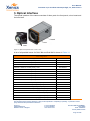
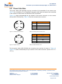
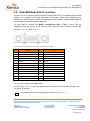
User Manual Gobi-640-17µm and Gobi-384-25µm-GigE, CL, CXP Camera 4.2. Power Interface The power cable (ASY-001268) must be connected to the backside of the camera (see (Ref. 2) for its location). For a Gobi-GigE, the power cable does not need to be connected to the camera in case Power over Ethernet (PoE) is foreseen. Figure 4-1 shows schematically the pin location of the power connector on the camera (Hirose HR10-7R-4SA(73)). Table 4-2 lists the connector pins overview. 4 1 3 2 Figure 4-1 Camera power connector Figure 4-2 Cable connector Pin Signal 1 + 12V 2 + 12V 3 Gnd 4 Gnd Table 4-2 Camera power connector 12VDC Pin Signal 1 + 12V 2 + 12V 3 Gnd 4 Gnd Table 4-3 Cable connector 12VDC For the power cable (ASY-001268) the connector pins overview is shown in Table 4-3. Figure 4-2 shows schematically the pin location of the cable connector (Hirose HR10-7P4P(73)). Company confidential. This document is the property of Xenics. It may not be reproduced – completely or partially – or passed to a third party without written permission from Xenics. Xenics nv Ambachtenlaan 44 BE-3001 Leuven Belgium T +32 16 38 99 00 F +32 16 38 99 01 www.xenics.com Doc Ref: ENG-2012-UMN007 Issue: R003 Date: 13/06/2014 XF-104_02/20-01-2012 Page 21 of 28