1
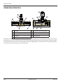
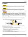
Installation
INSTALLATION
THIS PRODUCT SHOULD BE INSTALLED AND SERVICED BY TECHNICALLY QUALIFIED PERSONNEL TRAINED IN
MAINTAINING INDUSTRIAL CLASS FLOW INSTRUMENTATION AND PROCESSING EQUIPMENT.
READ INSTRUCTIONS THOROUGHLY BEFORE INSTALLING THE FLOW SENSOR. IF YOU HAVE ANY QUESTIONS
REGARDING PRODUCT INSTALLATION OR MAINTENANCE, CALL YOUR LOCAL SUPPLIER OR THE FACTORY FOR MORE
INFORMATION.
DO NOT USE MALE PIPE THREADS (NPT) INTO SAE STRAIGHT THREAD PORTS. USING MALE PIPE THREADS (NPTF)
WITH A FLOW SENSOR POSSESSING SAE STRAIGHT THREAD O-RING PORTS WILL NOT CREATE A PROPER SEAL AND
IS POTENTIALLY DANGEROUS. PIPE THREADS INSERTED INTO AN SAE STRAIGHT THREAD PORT ONLY ALLOW THE
ENGAGEMENT OF ONE OR TWO THREADS. NO AMOUNT OF TIGHTENING OR THREAD SEAL WILL STOP THE LEAKING
OR MAKE THE INSTALLATION SAFE. FAILURE TO FOLLOW THESE INSTRUCTIONS COULD RESULT IN SERIOUS PERSONAL
INJURY OR DEATH AND/OR DAMAGE TO THE EQUIPMENT.
Installation Recommendations
The in-line flow sensor is a simple device to install. However, the following measures are recommended for reliable,
trouble-free operation:
1. Provide at least 10 port diameters of upstream straight pipe with no obstructions to the flow sensor and at least 5
diameters of downstream pipe. The pipe should be of the same diameter as the nominal port size.
1" PORT
(25.4 mm)
END VIEW
5 PORT DIAMETERS
10 PORT DIAMETERS
10" (254 mm)
5" (127 mm)
IN
Example:
An FSC-1000 has a 1 in. (25.4 mm) port. The unobstructed upstream length should be at least 10 in. (254 mm) and the
downstream length should be at least 5 in. (127 mm).
2. Choose a position for the flow sensor that is not at the lowest level in the system. Placing the flow sensor at a higher
elevation in the system will avoid collection of debris, sediment and dirt in the flow sensor.
3. Use a filter. All applications should be filtered to at least 40 micron.
4. Do not install a flow sensor directly in-line with the outlet of a pump, as pressure pulsations can react with the turbine.
Install the sensor after another component, observing the 10 port diameter rule.
5. Do not adjust the magnetic pickup on the flow sensor. This is calibrated at the factory. Further adjustment will cause a
decrease in performance or damage to the sensor.
6. Do not exceed the working temperature range of –4…300° F (–20…150° C). Higher temperatures will damage the
magnetic pickup and lower temperatures will limit the rotation of the turbine.
March 2015
SEN-UM-00987-EN-02
Page 7