1
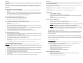
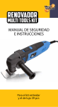
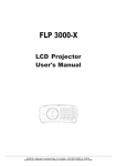
PORTABLE SOLAR GENERATOR
USER MANUAL
Solarpod™ 240 User Manual RevEU130924 (For Models: 03-SP240-01
01 / 02 / 03 / 11)
Solarpod™ 240 by Sunbird Solar
Sunbird Solar Solarpod™ 240 is a remarkably light 4.3kg/9.5lb.. portable power center with a full,
240 watt-hours
hours of rechargeable power to bring portable energy to your home, office, or job site.
Whether as a backup power supply for areas experiencing power outages due to natural disaster or
as a mobile generator for a campsite, the Solarpod™ 240 powers your world. Charge it from
available electricity or operate self-sufficiently using one of the Sunbird Solar Ltd. Solar Panels. No
set-up is required, just plug in and go. Includes a 12V & AC chargers and a cable to connect directly
to a solar panel. The internal LiFePO4 battery and energy management system is the one most
advanced on the market with a long life cycle and reliable performance.
Section 1________________________________________________________________________
____________________________________
IMPORTANT WARNINGS AND SAFEGUARDS
Read all instructions thoroughly before operating this unit to avoid injury to self or property and
avoid damage to the unit. Keep instructions handy for reference during use.
DANGER
ENERGIZED EQUIPMENT – ELECTRICAL SHOCK AND EXPLOSION HAZARDS
•
Do Not submerge in liquid or operate in wet environments. Device is not
waterproof or water resistant. Operate in dry environments only.
•
Do Not operate in flammable or explosive environments
•
Do Not operate if the unit is damaged in any way including loose electronics
or if charging cords are frayed and wires are exposed.
•
Do Not place foreign objects inside of the power outlets.
•
Do Not disassemble. There are no user serviceable parts. C
Contact
manufacturer for all repairs.
_________________________________________________________________________
•
•
•
CAUTION
•
•
•
Do Not use to operate any medical life support equipment.
equipment
Consult your physician before using with CPAP devices or other non-life
support medical equipment.
Administer close supervision when operating around children or persons
with disabilities.
Do Not use any devices over 400W for risk of damage to the inverter.
Do Not block the air inlets.
Not recommended for use or storage below 14ºF (-10ºC)
10ºC) or above 120ºF
(49ºC). If using above 120ºF, place out of direct sunlight to prevent
overheating.
FCC REQUIREMENTS
Warning: Changes or modifications to this unit not expressly approved by the party
responsible for compliance could void the user’s authority to operate the equipment.
NOTE: This equipment has been tested and found to comply with the limits for a Class B digital
device, pursuant to Part 15 of the FCC Rules. These limits are designed to provide reasonable
protection against harmful interference in a residential ins
installation. This equipment generates,
uses, and can radiate radio frequency energy
gy and, if not installed and used in ac
accordance with the
instructions, may cause harmful interference to radio communications. However, there is no
guarantee that interference will not occur in a particular installation. If this equipment does cause
harmfull interference to radio or television reception, which can be determined by turning the
equipment off and on, the user is encouraged to try to correct the interference by one of more of
the following measures:
•
Reorient or relocate the receiving antenna
•
Increase
rease the separation between the equipment and receiver
•
Connect the equipment into an outlet on a circuit different from that to which the
receiver is connected
•
Consult the dealer or an experienced radio/TV technician for help
Operation is subject to the following
ollowing two conditions: (1) this device may not cause harmful
interference, and (2) this device must accept any interference received, including interference that
may cause undesired operation.
Section 3________________________________________________________________________
PARTS IDENTIFICATION
Power Button
(Green LED)
Battery Capacity Charge Rate
(Blue LEDS)
(Yellow LEDS)
AC Power Button
(Red LED)
Top: Display & Controls
Section 2________________________________________________________________________
WARRANTY
Solarpod™ 240 is only serviceable by an authorized repair facility. Do not dismantle. Warranty
•
is void if the device is opened by unauthorized personnel. For technical support, contact your
local distributor or go to www.sunbird-solar.com/technical_support.
•
Registration for the limited warranty described on Sunbird Solar Ltd. website can be
completed by going online to www.sunbird-solar.com/warranty_registration
solar.com/warranty_registration. This is the sole
and exclusive warranty provided
vided by Sunbird Solar Ltd. In no event will Sunbird Solar Ltd. be
liable for any indirect or incidental damages or losses of any kind arising from or as a result of
misuse or abuse, or the incorrect installation or operation of the product.
Double
USB
Port
AC
Output
DC Fuse
DC 12V
Output
DC Charge
Input
Front: Output Side
AC Fuse
Back: Input Side
Section 4________________________________________________________________________
CHARGING
Fully charge before first use. For maximum efficiency, charge after each use or every 2 months if it
is being stored. Failure to properly charge as listed below could damage the unit and affect
performance. CAUTION: ONLY USE CHARGERS PROVIDED WITH THE SOLARPOD 240 OR DAMAGE
MAY OCCUR.
Section 5________________________________________________________________________
OPERATING INSTRUCTIONS
Once charged, the Solarpod™ 240 is ready to use right out of the box. No set up is required. All
outputs may be used simultaneously. Check your device’s specifications to make sure they are
compatible with the Solarpod™ 240.
ON/OFF Button - When on, the switches surrounding LED light will turn green.
Charging Indicator - Indicates Charging Rate
1. Five yellow LEDs represent the charging rate when using any of the methods of charging
below.
2. Each yellow LED equals approximately 20% charge rate. This will help you to position a solar
panel in the best angle to the sun. If the Solarpod™ 240 is plugged into a 100V – 240VAC or
12V - 24VDC power source, all 5 LEDs should be illuminated.
Battery Indicator - Indicates Battery Capacity Level
1. Five blue LEDs represents the current battery capacity.
2. Each blue LED represents approximately 20% full.
Solar Charging (recommended Sunbird Solar 60W Solar Panel)
1. The Solarpod™ 240 has built-in battery protection and does not require a solar charge
controller.
2. Place the solar panel in direct sun.
3. Connect the solar charging cable (included) male pin tip to the DC IN port on the Solarpod™
240. Connect the MC4 (+) and (-) tips to the solar panel.
4. Adjust the solar panel so that it is directly facing the sun. Charging will begin immediately and
the yellow charging LED indicators will illuminate.
5. To ensure full battery charge, continue charging for 1 additional hour.
6. To maximize battery cycle life, disconnect when Solarpod™ 240 is fully charged.
AC Wall Charging (Adapter Included)
1. Connect the male pin tip of the AC Wall Charger into the DC IN port of the Solarpod™ 240 and
then plug the other end into an electrical outlet.
2. The charging indicator on the AC Wall Charger will illuminate red when charging is in process
and green when the Solarpod™ 240 has reached a full charge.
3. The yellow charging LED indicators will also illuminate.
4. To ensure full battery charge, continue charging for 1 additional hour after Solarpod™ 240 is
fully charged.
5. There is no need to disconnect AC Wall Charger when charging is complete.
12V DC Vehicle Charging (Adapter Included)
CAUTION: The vehicle engine must be operating to maintain the proper vehicle battery level
required to charge the Solarpod™ 240. Vehicle battery discharge or slow charging to the Solarpod™
240 could occur.
1. Connect the male pin tip of the 12V DC Vehicle Charger into the DC IN port of the Solarpod™
240 and then plug the other end into a vehicle power outlet.
2. The charging indicator on the 12V DC Vehicle Charger will illuminate red when charging is in
process and change to green when charging is complete.
3. The yellow charging LED indicators will also illuminate.
4. To ensure full battery charge, continue charging for 1 additional hour after Solarpod™ 240 is
fully charged.
5. There is no need to disconnect 12V DC Vehicle Charger when charging is complete.
AC Power Button - When on, the switches surrounding LED light will turn red.
USB Operation
•
Turn the ON/OFF BUTTON on.
•
Plug in your device’s USB power or charging cable.
•
A combined 5V/2A maximum output is available between the two ports (when fully
charged).
•
Disconnect and power off when not in use.
AC Operation (max 400W output)
•
Press the AC power button to activate the inverter.
•
Plug in your device’s power or charging cable into the electrical AC socket.
•
Disconnect and turn off the power when not in use.
•
CAUTION: CHECK CAREFULLY THAT THE VOLTAGE RATING OF YOUR APPLIANCE MATCHES
THE VOLTAGE RATING OF THE Solarpod™ 240 UNIT YOU HAVE PURCHASED.
•
CAUTION: Using devices rated higher than 350-400W and operated for more than 10
minutes may cause the Solarpod™ 240 to overheat and shut down. Once it has cooled
the circuit will reset and the Solarpod™ 240 will be operational again.
Modified Sine Wave Inverter Information
Modified side wave inverters are the most common type on the market and work well for
most uses. It is designed for use with small electronic equipment up to the power limits
specified of 400W.
Due to the nature of the electrical output from this inverter, some devices using variable
speed controllers and solid-state power will require the use of a Pure Sine Wave inverter
(found in the Solarpod™ Pro 1000). You may notice additional noise from audio equipment or
devices with electric motors.
Unsuitable Devices
Use of any of the following items with Solarpod™ 240 is at the user’s own risk and Sunbird
Solar Ltd. does not accept any responsibility for damage or injury resulting from use.
•
Fluorescent lights with electronic ballasts
•
Power tools with solid state power or variable speed control
•
Digital clocks with radios
•
Sewing machines with speed/microprocessor control
•
X-10 home automation systems
•
Medical equipment such as oxygen concentrators
12V DC Operation (Max 15A output)
•
Plug in your 12V device’s power or charging cable into the 12V Vehicle Socket.
•
Neither power button need to be on.
•
Disconnect and power off when not in use.
Section 6________________________________________________________________________
CARE AND MAINTENANCE
•
Dust regularly with a clean dry cloth to prevent dust and dirt from building up on the
vents and power inputs/outputs. Store in a clean, dry place when not in use.
•
Charge after each use, every 30-60 days, and before storing so it is ready to use when
needed.
•
Solarpod™ 240 is only serviceable by an authorized repair facility. Do not dismantle.
Warranty is void if the device is opened by unauthorized personnel. For technical
support, contact your local distributor or go to www.sunbirdsolar.com/technical_support for online technical support.
Section 7________________________________________________________________________
TROUBLESHOOTING
If our Solarpod™ 240 fails to operate as specified, follow these troubleshooting steps to correct the
issue. If you still experience issues, please contact your local distributor or go to www.sunbirdsolar.com/technical_support for online technical support.
Charging Issues
•
Ensure all cords are connected securely.
•
Check power indicators on chargers and the Solarpod™ 240 to verify they are operating.
•
If using a solar panel to charge, ensure it is correctly positioned in direct sunlight.
•
If using the 12V DC Vehicle Charger make sure the vehicle it is connected to is operating.
•
Check that the fuses on the Solarpod™ 240 have not blown.
Section 8________________________________________________________________________
TECHNICAL INFORMATION
SPECIFICATIONS
Battery Type
Battery Lifespan
Protection Circuit
Fuses (replaceable)
DC Input Power
AC Wall Charger
12V DC Vehicle
Charger
Rated Output Power
(amp-hours)
Operating
Temperature
Dimensions
Weight
Certifications
LiFePO4 (lithium iron phosphate) 12V, 20Ah
2000+ cycles (cycle = charge and discharge)
Built-in over voltage, self discharge, temperature and short circuit protection
2A OR 4A fuse (AC outlet) and 15A fuse (12V DC outlet) (See fuse chart below)
14.6V/4A
Input: 100-240V, 50/60Hz, 70VA
Output: 14.6V-15V DC, 4A,
C-UL, FCC approved
Input: 12-30V DC (regulated)
Output: 14.6V-15V DC, 2A
AC 230V, 400W Max, Modified Sine Wave Inverter, (20Ah)
12V DC, 15A, 180W Max (20Ah)
One Double USB 5V, 2A, 10W Max - (20Ah)
32ºF to 113ºF
0ºC to 45ºC
255 x 195 x 110mm
4.3kg / 9.5lb
CE: Low voltage directive 2006/95/EC, Electromagnetic Compatibility directive
2004/108/EC
FCC: VOC, Part 15B
SOLARPOD™ 240 CHARGING TIME (from fully discharged)
12V DC Output Fails
•
Check the battery indicator (blue LED strip) to see if the Solarpod™ 240 has sufficient
battery charge available. If not, follow the charging steps previously described.
•
Check to make sure that the 12V DC circuit protection fuse is not blown by removing the
15A fuse housing cap. Inspect the fuse and replace if needed with the same size fuse.
•
Check the 12V DC output socket for obstructions or other visible damage.
•
Verify the device being charged is not damaged.
AC Output Fails
•
Check the battery indicator (blue LED strip) to see if the Solarpod™ 240 has sufficient
battery charge available. If not, follow the charging steps previously described.
•
Ensure the AC power button is on and the red light is on.
•
Check to make sure that the AC circuit protection fuse is not blown by removing the 2A or
4A fuse housing cap and then removing the 2A or 4A fuse. Inspect the fuse and replace if
needed with the same size fuse (See Section 8 for AC fuse reference chart).
•
Check the AC output socket for obstructions or other visible damage.
•
Verify the device being charged is not damaged.
USB Output Fails
•
Check the battery indicator (blue LED strip) to see if the Solarpod™ 240 has sufficient
battery charge available. If not, follow the charging steps previously described.
•
Ensure the ON/OFF power is on and the green light is on.
•
Check the USB port for obstructions or other visible damage.
•
Verify the device being charged is not damaged.
Using 60-Watt Solar Panel
Using AC Wall Charger (included)
12V DC Vehicle Charger (included)
Appliance
6 - 7 hours (in full sunlight)
5 hours
7 - 8 hours
OPERATING TIME
Solarpod™ 240
USB Output Port
iPhone*/Android** Phone recharge (6.48Wh)
36 times
iPad*/Tablet recharge (25Wh)
10 times
12V Output Port
12V Fan (35W)
6.5 hours
12V Cooler (50W)
4.5 hours
12V Flat Screen 19" TV (70W)
3.2 hours
AC Inverter Outlet
LED Camp Lights (3W)
66 hours
Small Refrigerator (40W)
5 hours
Laptop battery (50Wh) recharge
4 times
LED Projector (60W)
3.3 hours
32''LCD TV (90W)
2.2 hours
*iPhone is a trademark of Apple Inc.
**Android is a trademark of Google Inc.
NOTE: Data is approximated and based on the maximum power consumption.
SOLARPOD™ 240 AC Fuse Reference Chart
110V AC Units
230V AC Units
12V DC Output Fuse
4 Amp Fuse
2 Amp Fuse
15 Amp Fuse
Solarpod™ Pro 1000
145 times
38 times
25.5 hours
18 hours
12.5 hours
272 hours
20 hours
16 times
13.5 hours
9 hours