1
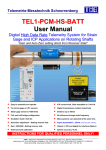
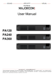
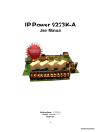
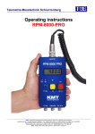
Telemetrie-Messtechnik Schnorrenberg IND-PWR XXL RING COIL User Manual Inductive power supply set Power supply for power head Inductive ring coil CUL 1.00 mm for IND-DATA coil CUL 0.63 mm for IND-PWR coil (Enamelled copper wire) AC/DC Adapter 120Watt (24V 5A) IND-PWR AC/DC module Input: AC from coil Output 5VDC max. 1000mA Power Head with 5m cable TMS • Telemetrie-Messtechnik Schnorrenberg • Dipl.-Ing. Werner Schnorrenberg Habichtweg 30, D-51429 Bergisch Gladbach, Tel: 02204-9815-52, Fax: 02204-9815-53, Mobil: 0171-8902387 Bankverbindung: Sparkasse KölnBonn, Kto.-Nr: 1900310663, BLZ: 370 501 98 MT32-IND-PWR 5V - AC/DC Module for inductive power MT32-IND-PWR 5V AC/DC Module for inductive power Input: 30-60kHz, 10-50V AC Output: 5 VDC Current: up to 1000mA Weight: 35 gram Vibration: 5g Shock: 3000g Pin assignment 5.0V OUTPUT Max. 1000mA IND- PWR COIL AC INPUT 30-60kHz GND IND AC IND AC 5V At current up to 500mA use one pin At current up to 1000mA use two pins Status LED LED ON = right windings and good distance between head and coil LED very low blinking = too less windings of IND-Coil or too large distance between head and coil! LED fast blinking = too much windings (OVER POWER at IND-Coil) reduce windings or module go hot and switch OFF (internal thermo switch!) Version 2011-06b 2 MT32 IND-PWR housing - dimensions Weight about 35 grams Version 2011-06b 3 Inductive power supply RING COIL - Distance power head and pickup head Solder pins for power coil and wire to IND-PWR 5V. Please use twisted wire (>=0.25mm) IND-Data Pickup Distance to coil 5-100mm IND-PWR Head Distance to coil 5-30 mm CUL 1.00 mm for IND-DATA coil - 1 winding CUL 0.63 mm for IND-PWR coil - 5 winding (Enamelled copper wire) IND-Data Pickup Distance to coil +/-50mm IND-Data Pickup Distance to coil +/-50mm Solder pins for data coil and wire to IND-TX 40MHz. Please use twisted wire (>=0.14mm) If you use longer wires >100mm, please shied the wires! max. 1000mm recommend (only shielded!) Version 2011-06b 4 Inductive power supply RING COIL – Distance power head PWR-COIL 5 winding with CUL wire 0.63mm DATA-COIL 1 winding with CUL wire 1.00mm (Enamelled copper wire) (Enamelled copper wire) Distance 5-30mm Distance +/-4mm Version 2011-06b 5 Inductive power supply RING COIL inner diameter 196mm Version 2011-06b 6 Inductive power supply RING COIL inner diameter 191mm Version 2011-06b 7 Dimensions of IND-PWR-HEAD-XXL Version 2011-06b 8 Dimensions of IND-PWR-HEAD-XXL Version 2011-06b 9 IND-PWR-HEAD-XXL Caution for use of power heads! Cable must unrolled for use, otherwise it will warm up! Version 2011-06b 10 MT32-IND-PWR Following must be considered at the mounting of the inductive power head Shaft with Cu wire Coil Magnetic field 25-30mm Don’t use for mounting any kind metal in this area (25-30mm)! Otherwise magnetic energy will flow in the metal and decrease the distance between power head and coil (on shaft)! Example of mounting Wrong!!! Mounting (only if metal) plate cover the active area of inductive head Version 2011-06b 11 MT32-IND-PWR-XXL Pin connection CONTROL - Not used! IN DC 24V 5A DC 24V (100 WATT) AC 25-35kHz output for power head E= have no function Powering and AC out LED flashing = auto adjustment LED ON = finish IND-resonance of Power head reached! Control out of function Power control LED Power Switch IN DC 24V 5A AC 25-35kHz output for power head Power INPUT DC 24V (100WATT) Version 2011-06b 12 Safety notes for inductive powering The device should only applied by instructed personnel. The power head emits strong magnetic radiation at 30-60 kHz to a distance of 20 cm. Therefore persons with cardiac pacemakers should not work with this device! Magnetic data storage media should be kept in a distance of at least 3m from the power head to avoid data loss. The same is valid for electromagnetic sensitive parts, devices and systems. Do not place the power head in the switched-on state on metallic objects, because this results in eddy currents which could overload the device and strong heat up small objects. Also the probe could be destroyed! No metallic objects, other than the disc-type coil, should be located in the air gap of the power head. The same applies to metallic parts within a radius of up to 30 mm in all directions. Do not use damaged or faulty cables! Never touch in the area between shaft and inductive head, the rotating shaft itself or rotor electronic contacts during operation! This is a “Class A” system suitable for operation in a laboratory or industrial environment. The system can cause electromagnetic interferences when used in residential areas or environments. In this case the operator is responsible for establishing protective procedures. Version 2011-06b 13