1
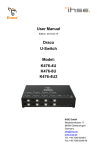
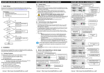
User Manual Edition: 2014-04-15 Draco (Cross) Repeater Model: 485 Series IHSE GmbH Maybachstrasse 11 88094 Oberteuringen Germany [email protected] www.ihse.de Tel. +49 7546-9248-0 Fax +49 7546-9248-48 Draco (Cross) Repeater Copyright © 2014. All rights reserved. This information may not be reproduced in any manner without the prior written consent of the manufacturer. Information in this document is subject to change without notice. Trademarks All trademark and trade names mentioned in this document are acknowledged to be the property of their respective owners. Disclaimer While every precaution has been taken during preparation of this manual, the manufacturer assumes no liability for errors or omissions. The manufacturer assumes no liability for damages resulting from the use of the information contained herein. The manufacturer reserves the right to change specifications, functions, or circuitry of the product without notice. The manufacturer cannot accept liability for damage due to misuse of the product or due to any other circumstances outside the manufacturer’s control (whether environmental or installation related). The manufacturer shall not be liable for any loss, damage, or injury arising directly, indirectly, incidentally, or consequently from the use of this product. 2 2014-04-15 Contents Contents 1 About This Manual ....................................................................... 5 1.1 Scope.................................................................................. 5 1.2 Validity ................................................................................ 5 1.3 Cautions and Notes ............................................................ 5 2 Safety Instructions ....................................................................... 6 3 Description ................................................................................... 7 3.1 Application .......................................................................... 7 3.2 System Overview ................................................................ 8 3.3 Product Range .................................................................... 9 3.3.1 Chassis ................................................................. 9 3.3.2 (Cross) Repeater Modules .................................. 10 3.4 Accessories Upgrade Kits ................................................. 10 3.5 Accessories....................................................................... 11 3.6 Device Views .................................................................... 11 3.6.1 3.7 3.6.2 2-fold Vario Chassis 474-BODY2N ..................... 12 3.6.3 4-fold Vario Chassis 474-BODY4/4R .................. 13 3.6.4 6-fold Vario Chassis 474-BODY6R ..................... 14 3.6.5 6-fold Vario Chassis 474-BODY6BP................... 15 3.6.6 6-fold Vario Chassis 474-BODY6BPF................. 16 3.6.7 21-fold Vario Chassis 474-BODY21R ................. 17 3.6.8 Model 485-BC ..................................................... 18 3.6.9 Model 485-BS ..................................................... 18 3.6.10 Model 485-BX ..................................................... 18 3.6.11 Model 485-BCC .................................................. 19 3.6.12 Model 485-BSS................................................... 19 3.6.13 Model 485-BXX................................................... 20 Status LEDs ...................................................................... 21 3.7.1 2014-04-15 2-fold Vario Chassis 474-BODY2/2R .................. 11 Status (Cross) Repeater Module......................... 21 3 Draco (Cross) Repeater 4 Installation .................................................................................. 22 4.1 Package Contents............................................................. 22 4.2 System anschließen.......................................................... 22 4.2.1 4.3 (Cross) Repeater Setup ...................................... 22 Example Applications........................................................ 23 5 Configuration.............................................................................. 25 6 Operation .................................................................................... 25 7 Specifications ............................................................................. 26 7.1 7.2 7.3 8 10 11 RJ45 (Interconnect) ............................................ 26 7.1.2 Fiber SFP Type LC (Interconnect) ...................... 26 Interconnect Cable ............................................................ 27 7.2.1 Cat X ................................................................... 27 7.2.2 Fiber.................................................................... 28 Connector Pinouts ............................................................ 29 7.4 Power Supply.................................................................... 30 7.5 Environmental Conditions ................................................. 30 7.6 Size ................................................................................... 31 7.7 Shipping Weight ................................................................ 32 Troubleshooting ......................................................................... 33 8.1 9 Interfaces .......................................................................... 26 7.1.1 General Failures ............................................................... 33 Technical Support ...................................................................... 34 9.1 Support Checklist .............................................................. 34 9.2 Shipping Checklist ............................................................ 34 Certificates.................................................................................. 35 10.1 CE Declaration Of Conformity........................................... 35 10.2 North American Regulatory Compliance ........................... 36 10.3 Product Safety .................................................................. 36 10.4 WEEE ............................................................................... 37 10.5 RoHS/RoHS 2................................................................... 37 Glossary...................................................................................... 38 Pos: 1 /806-IHSE/Zu diesem Handbuch/ATB_Zu diesem Handbuch @ 5\mod_1278573163276_6.doc @ 41510 @ 1222 @ 1 4 2014-04-15 About This Manual 1 About This Manual 1.1 Scope This manual describes how to install your (Cross) Repeater, how to operate it and how to perform trouble shooting. 1.2 Validity This manual is valid for all devices listed on the front page. The product code is printed on the base of the devices. 1.3 Cautions and Notes The following symbols are used in this manual: This symbol indicates an important operating instruction that should be followed to avoid any potential damage to hardware or property, loss of data, or personal injury. This symbol indicates important information to help you make the best use of this product. This symbol indicates best practice information to show recommended and optimal ways to use this product in an efficient way. Pos: 2 /806-IHSE/Sicherheitshinweise/ATB_Sicherheitshinweise @ 5\mod_1278573321245_6.doc @ 41528 @ 1 @ 1 2014-04-15 5 Draco (Cross) Repeater 2 Safety Instructions To ensure reliable and safe long-term operation of your (Cross) Repeater please note the following guidelines: Installation Only use in dry, indoor environments. The (Cross) Repeater and the power supply units can get warm. Do not install components in an enclosed space without any airflow. Do not place the power supply directly on top of the device. Do not obscure ventilation holes. Only use power supplies originally supplied with the product or manufacturer-approved replacements. Do not use a power supply if it appears to be defective or has a damaged chassis. Connect all power supplies to grounded outlets. In each case, ensure that the ground connection is maintained from the outlet socket through to the power supply's AC power input. Do not connect the link interface to any other equipment, particularly network or telecommunications equipment. Take any required ESD precautions. In order to disconnect the device completely from the electric circuit, all power cables have to be removed. Repair Do not attempt to open or repair a power supply unit. Do not attempt to open or repair the (Cross) Repeater. There are no user serviceable parts inside. Please contact your dealer or manufacturer if there is a fault. Pos: 3 /806-IHSE/Beschreibung/UEB_Beschreibung @ 5\mod_1278573379151_6.doc @ 41546 @ 1 @ 1 6 2014-04-15 Description 3 Description Pos: 4 /806-IHSE/Beschreibung/Verwendungszweck/485-xx @ 11\mod_1395145109102_6.doc @ 140748 @ 2 @ 1 3.1 Application The (Cross) Repeater is basically used in order to double the maximum cabling distance between a KVM extender CON or CPU Unit or even a KVM matrix. In addition to that the device can also be used for media conversion from Cat X to fiber or vice versa. The device is available as a pure Cat X or fiber version (repeater) and as a hybrid version of Cat X and fiber (cross repeater) for an additional electrical/optical signal conversion. Pos: 5 /806-IHSE/Beschreibung/System-Übersicht /485-xx @ 11\mod_1395145337503_6.doc @ 140779 @ 2 @ 1 2014-04-15 7 Draco (Cross) Repeater 3.2 System Overview The (Cross) Repeater consists of at least one module depending on the application. The device is connected between a KVM extender CON and CPU Unit via the interconnect cable or can be alternatively connected between a KVM extender unit and a KVM matrix. The (Cross) Repeater communicates with both the KVM extenders and a KVM-Matrix via the interconnect cables. 1 2 3 4 5 6 7 System Overview 1 Source (computer, CPU) 2 KVM Extender CPU Unit 3 Interconnect cable (Cat X or fiber) 4 (Cross) Repeater 5 Interconnect cable (Cat X or fiber) 6 KVM Extender CON Unit 7 Console (monitor, keyboard, mouse) See Chapter 4.3, Page 23 for installation examples. Pos: 6 /806-IHSE/Beschreibung/Gerätetypen/485-xx @ 11\mod_1395145641436_6.doc @ 140805 @ 233 @ 1 8 2014-04-15 Description 3.3 Product Range 3.3.1 Chassis Model Description 474-BODY2 Empty chassis for up to 2 boards, 1x external power supply unit 474-BODY2R Empty chassis for up to 2 boards, 1x external power supply unit, preparation for redundancy for a second power supply unit (external) 474-BODY2N Empty chassis for up to 2 boards, 1x internal power supply unit, preparation for redundancy for a second power supply unit (external) 474-BODY4 Empty chassis for up to 4 boards, 1x external power supply unit 474-BODY4R Empty chassis for up to 4 boards, 1x external power supply unit, preparation for redundancy for a second power supply unit (external) 474-BODY6R Empty chassis for up to 6 boards, 1x internal power supply unit, preparation for redundancy for a second power supply unit (external) 474BODY6BP Empty chassis for up to 6 boards, active backplane, 2x internal power supply unit (redundancy) 474BODY6BPF Empty chassis for up to 6 boards, active backplane, 2x internal power supply unit (redundancy) with connectors on rear side 474BODY21/4U Empty chassis for up to 21 boards, 1x internal power supply unit, preparation for redundancy for a second power supply unit (internal) 2014-04-15 9 Draco (Cross) Repeater 3.3.2 (Cross) Repeater Modules Model Description 485-BC Repeater module Cat X for range extension up to 280 m 485-BS Repeater module fiber (Single-Mode) for range extension up to 20,000 m 485-BX Repeater module Cat X/fiber (Single-Mode) for an electrical/optical media conversion, maximum extension 10,140 m 485-BCC Dual repeater module Cat X for range extension up to 280 m 485-BSS Dual repeater module fiber (Single-Mode) for range extension up to 20,000 m 485-BXX Repeater module Cat X/fiber (Single-Mode) for an electrical/optical media conversion, maximum extension 10,140 m Pos: 7 /806-IHSE/Beschreibung/Einbauoptionen/474-xx @ 6\mod_1304580008551_6.doc @ 50839 @ 2 @ 1 3.4 Accessories Upgrade Kits Model Description 474-2RMK 19"/1U rack mount kit for 2-fold chassis 4742NRMK 19"/1U rack mount kit for 2-fold chassis with internal PSU 474-4RMK 19"/1U rack mount kit for 4-fold chassis 474-6RMK 19"/1U rack mount kit for 6-fold chassis 474VPLATE Fastening strips for screw or snap on for 2-, 4- and 6-fold chassis 474OPTRED Retrofitting for redundant power supply option (without power supply) for 2- and 4-fold chassis 474-PSU2 Power supply for 2-fold chassis (spare or redundancy) 474-PSU4 Power supply for 4-fold chassis (spare or redundancy) 474-PSU6 Power supply for 6-fold chassis (spare or redundancy) 474-PSU21 Power supply for 6-fold-chassis (spare or redundancy) 474-BLND1 Blind plate 3U/4HP for 2-, 4- and 6-fold chassis 474-BLND2 Blind plate 3U/8HP for 2-, 4- and 6-fold chassis 10 2014-04-15 Description (Cross) Repeaters and the power supply units can get warm and must not be installed in closed rooms with no air circulation. For rack-mount installations, at least 0.5 U (height unit) is required above the (Cross) Repeater for ventilation. Pos: 8 /806-IHSE/Beschreibung/Zubehör/485-xx @ 11\mod_1395145995119_6.doc @ 140842 @ 2 @ 1 3.5 Accessories Model Description 260-5G International power supply unit 100...240 VAC / 5 VDC / 3 A 260-5U International power supply unit 100...240 VAC / 5 VDC / 4 A 474PSULOCK IEC connection cable for power supply, lockable Pos: 9 /806-IHSE/Beschreibung/Geräteansichten/UEB_Geräteansichten @ 5\mod_1278573737808_6.doc @ 41654 @ 2 @ 1 3.6 Device Views Pos: 10 /806-IHSE/Beschreibung/Geräteansichten/474-xx/2-fach Vario-Gehäuse 474-BODY2/2R @ 6\mod_1304580280566_6.doc @ 50858 @ 3 @ 1 3.6.1 2-fold Vario Chassis 474-BODY2/2R CPU and CON Unit 3 4 1 2 Rear View 1 Slot for modules #1 2 Connect to 5VDC power supply (standard) 3 Slot for modules #2 4 Connect to 5VDC power supply (redundancy, optional) Pos: 11 /806-IHSE/Beschreibung/Geräteansichten/474-xx/2-fach Vario-Gehäuse 474-BODY2N @ 8\mod_1348578478411_6.doc @ 69380 @ 3 @ 1 2014-04-15 11 Draco (Cross) Repeater 3.6.2 2-fold Vario Chassis 474-BODY2N CPU and CON Unit 4 3 1 2 Rear View 1 Slot for modules #1 2 Connect to power supply (standard) 3 Slot for modules #2 4 Connect to 5VDC power supply (redundancy) The 2-fold vario chassis with an internal power supply is not equipped with a fuse on its primary side. Therefore the protection against excessive currents has to be provided by the electrical installation of the building. Pos: 12 /806-IHSE/Beschreibung/Geräteansichten/474-xx/4-fach Vario-Gehäuse 474-BODY4/4R @ 6\mod_1304580359098_6.doc @ 50876 @ 3 @ 1 12 2014-04-15 Description 3.6.3 4-fold Vario Chassis 474-BODY4/4R CPU and CON Unit 4 5 6 1 2 3 Rear View 1 Slot for modules #3 2 Slot for modules #1 3 Connect to 5VDC power supply (standard) 4 Slot for modules #4 5 Slot for modules #2 6 Connect to 5VDC power supply (redundancy, optional) For operation with three KVM Extender CON modules and a USB 2.0 CON module in a 4-fold vario chassis, two power supplies are necessary. In this case, redundancy is inapplicable. Pos: 13 /806-IHSE/Beschreibung/Geräteansichten/474-xx/6-fach Vario-Gehäuse 474-BODY6R @ 6\mod_1304580442488_6.doc @ 50894 @ 3 @ 1 2014-04-15 13 Draco (Cross) Repeater 3.6.4 6-fold Vario Chassis 474-BODY6R CPU and CON Unit 6 7 8 1 2 3 4 5 Rear View 1 Slot for modules #5 2 Slot for modules #3 3 Slot for modules #1 4 Connect to power supply (standard) 5 Connect to 5VDC power supply (standard) 6 Slot for modules #6 7 Slot for modules #4 8 Slot for modules #2 For operation with KVM Extender modules in a 6-fold vario chassis, two power supplies are necessary. In this case, redundancy is inapplicable. The 6-fold vario chassis is not equipped with a fuse on its primary side. Therefore the protection against excessive currents has to be provided by the electrical installation of the building. Pos: 14 /806-IHSE/Beschreibung/Geräteansichten/481-xx/6-fach Vario-Gehäuse 474-BODY6BP @ 9\mod_1367827188730_6.doc @ 71694 @ 3 @ 1 14 2014-04-15 Description 3.6.5 6-fold Vario Chassis 474-BODY6BP CPU and CON Unit 1 2 3 Front View 1 Connect to power supply 1 2 Connect to power supply 2 (redundancy) 3 Grounding 4 5 6 1 2 3 Rear View 1 Slot for modules #5 2 Slot for modules #3 3 Slot for modules #1 4 Slot for modules #6 5 Slot for modules #4 6 Slot for modules #2 Pos: 15 /806-IHSE/Beschreibung/Geräteansichten/474-xx/6-fach Vario-Gehäuse 474-BODY6BPF @ 11\mod_1392644763729_6.doc @ 132650 @ 3 @ 1 2014-04-15 15 Draco (Cross) Repeater 3.6.6 6-fold Vario Chassis 474-BODY6BPF CPU and CON Unit 6 7 8 1 2 3 4 5 Rear View 1 Slot for modules #5 2 Slot for modules #3 3 Slot for modules #1 4 Connect to power supply 1 5 Connect to power supply 2 (redundancy) 6 Slot for modules #2 7 Slot for modules #4 8 Slot for modules #6 Pos: 16 /806-IHSE/zz_Layout/Seitenumbruch @ 8\mod_1348581820516_0.doc @ 69462 @ @ 1 16 2014-04-15 Description Pos: 17 /806-IHSE/Beschreibung/Geräteansichten/474-xx/21-fach Vario-Gehäuse 474-BODY21R @ 8\mod_1348579151346_6.doc @ 69400 @ 3 @ 1 3.6.7 21-fold Vario Chassis 474-BODY21R CPU and CON Unit 1 Rear View 1 Slots for modules #1 - #21 1 2 3 4 Front View 1 Connect to power supply 2 2 Locking for power supply 2 (redundancy) 3 Locking for power supply 1 (standard) 4 Connect to power supply 1 Pos: 18 /806-IHSE/Beschreibung/Geräteansichten/485-xx/485-BC @ 11\mod_1395150015320_6.doc @ 140874 @ 3 @ 1 2014-04-15 17 Draco (Cross) Repeater 3.6.8 Model 485-BC Module 1 2 3 Rear View 1 Service port 2 Connect to interconnect cable 1 3 Connect to interconnect cable 2 Pos: 19 /806-IHSE/Beschreibung/Geräteansichten/485-xx/485-BS @ 11\mod_1395151298709_6.doc @ 140905 @ 3 @ 1 3.6.9 Model 485-BS Module 1 2 3 Rear View 1 Service port 2 Connect to interconnect cable 1 3 Connect to interconnect cable 2 Pos: 20 /806-IHSE/Beschreibung/Geräteansichten/485-xx/485-BX @ 11\mod_1395153879791_6.doc @ 140936 @ 3 @ 1 3.6.10 Model 485-BX Module 1 2 3 Rear View 1 Service port 2 Connect to interconnect cable 1 3 Connect to interconnect cable 2 Pos: 21 /806-IHSE/Beschreibung/Geräteansichten/485-xx/485-BCC @ 11\mod_1395153925309_6.doc @ 140967 @ 3 @ 1 18 2014-04-15 Description 3.6.11 Model 485-BCC Module 1 2 3 4 5 6 Rear View 1 Service port (repeater #1) 2 Connect to interconnect cable 1 (repeater #1) 3 Connect to interconnect cable 2 (repeater #1) 4 Service port (repeater #2) 5 Connect to interconnect cable 1 (repeater #2) 6 Connect to interconnect cable 2 (repeater #2) Pos: 22 /806-IHSE/Beschreibung/Geräteansichten/485-xx/485-BSS @ 11\mod_1395154011282_6.doc @ 140998 @ 3 @ 1 3.6.12 Model 485-BSS Module 1 2 3 4 5 6 Rear View 1 Service port (repeater #1) 2 Connect to interconnect cable 1 (repeater #1) 3 Connect to interconnect cable 2 (repeater #1) 4 Service port (repeater #2) 5 Connect to interconnect cable 1 (repeater #2) 6 Connect to interconnect cable 2 (repeater #2) Pos: 23 /806-IHSE/Beschreibung/Geräteansichten/485-xx/485-BXX @ 11\mod_1395154080863_6.doc @ 141029 @ 3 @ 1 2014-04-15 19 Draco (Cross) Repeater 3.6.13 Model 485-BXX Module 1 2 3 4 5 6 Rear View 1 Service port (repeater #1) 2 Connect to interconnect cable 1 (repeater #1) 3 Connect to interconnect cable 2 (repeater #1) 4 Service port (repeater #2) 5 Connect to interconnect cable 1 (repeater #2) 6 Connect to interconnect cable 2 (repeater #2) Pos: 24 /806-IHSE/Beschreibung/Diagnose LEDs/UEB_Diagnose_LEDs @ 6\mod_1304584004723_6.doc @ 51146 @ @ 1 20 2014-04-15 Description 3.7 Status LEDs Pos: 25 /806-IHSE/Beschreibung/Diagnose LEDs/485-xx @ 11\mod_1395154726794_6.doc @ 141055 @ 3 @ 1 3.7.1 Status (Cross) Repeater Module The (Cross) Repeater module is fitted with a multi color LED for overall status indication and with two further LEDs for indication of the connection status. Module 1 2 3 4 5 1 2 3 4 5 1 2 3 4 5 Rear View Rear View LED 1/2 and 4/5: Connection Status Pos. LED 1/4 2/5 Status Description Failure LED Off (green) On or Flashing Connection available Status LED (green) Flashing No connection via interconnect cable On Connection available Connection failure (flashing for about 20 s following a connection failure) LED 3: Device Status LED color Description Red Device ready Blue Link 1 (left connector) available, Link 2 (right connector) not detected Green Light Blue Link 2 (right connector) available, Link 1 (left connector) not detected Link 1 (left connector) and Link 2 (right connector) available Pos: 26 /806-IHSE/Installation/UEB_Installation @ 5\mod_1278574971589_6.doc @ 41768 @ 1 @ 1 2014-04-15 21 Draco (Cross) Repeater 4 Installation Pos: 27 /806-IHSE/Installation/Lieferumfang prüfen/485-xx @ 11\mod_1395155216299_6.doc @ 141092 @ 2 @ 1 4.1 Package Contents Your extender package contains the following items: (Cross) Repeater: (Cross) Repeater in the vario chassis 1x (redundancy 2x) 5 VDC international power supply unit per KVM Extender unit (depending on chassis) 1x (redundancy 2x) country-specific power cord (depending on chassis) Quick Setup If anything is missing, contact your dealer. Pos: 28 /806-IHSE/Installation/System anschließen/485-xx @ 11\mod_1395155663403_6.doc @ 141123 @ 23 @ 1 4.2 System anschließen First time users are recommended to setup the system in the same room as a test setup. This will allow you to identify and solve any cabling problems, and experiment with your system more conveniently. Please verify that interconnect cables, interfaces, and handling of the devices comply with the requirements (see Chapter 7, Page 26). 4.2.1 (Cross) Repeater Setup 1. Switch off all devices. 2. Connect the (Cross) Repeater with the interconnect cable(s). 3. Connect the chassis of the (Cross) Repeater to the power supply. 4. Power up the system. To power up the system, the following sequence is recommended: Monitor – CON Unit – (Cross) Repeater – CPU Unit – source. Pos: 29 /806-IHSE/Installation/Installationsbeispiele/485-xx @ 11\mod_1395156295171_6.doc @ 141154 @ 2 @ 1 22 2014-04-15 Installation 4.3 Example Applications This section illustrates typical installations of (Cross) Repeaters: Pos: 58 /806-IHSE/Installation/Installationsbeispiele/477-xx_COMP @ 5\mod_1291124264328_258.doc @ 44766 @ @ 1 1 2 3 4 5 6 7 Single Media Conversion 1 Source (computer, CPU) 2 KVM Extender CPU Unit 3 Interconnect cable (Cat X) 4 (Cross) Repeater 5 Interconnect cable (fiber) 6 KVM Extender CON Unit 7 Console (monitor, keyboard, mouse) The example shown in this application scenario will be primarily recommended, if connections through KVM matrix must be bypassed in case of major matrix problems. Therefore KVM extenders with Cat X and with fiber connector can be directly connected to each other. 2014-04-15 23 Draco (Cross) Repeater 1 2 3 4 5 6 7 8 9 Pos: 46 /806-IHSE/zz_Layout/Seitenumbruch @ 8\mod_1348581820516_0.doc @ 69459 @ @ 1 Dual Media Conversion 1 Source (computer, CPU) 2 KVM Extender CPU Unit 3 Interconnect cable (Cat X) 4 (Cross) Repeater #1 5 Interconnect cable (fiber) 6 (Cross) Repeater #2 7 Interconnect cable (Cat X) 8 KVM Extender CON Unit 9 Console (monitor, keyboard, mouse) Pos: 30 /806-IHSE/Konfiguration/UEB_Konfiguration @ 5\mod_1278575517073_6.doc @ 41846 @ 1 @ 1 24 2014-04-15 Configuration 5 Configuration Pos: 31 /806-IHSE/Konfiguration/485_Einleitung @ 11\mod_1395156666210_6.doc @ 141185 @ @ 1 The (Cross) Repeater does not require any configuration and is ready for use per default. Pos: 32 /806-IHSE/Betrieb/UEB_Betrieb @ 5\mod_1278577614980_6.doc @ 41970 @ 1 @ 1 6 Operation Pos: 33 /806-IHSE/Betrieb/485_Einleitung @ 11\mod_1395156725331_6.doc @ 141216 @ @ 1 The (Cross) Repeater does not have any adjustable operating modes and is ready for use per default. Pos: 34 /806-IHSE/Technische Daten/UEB_Technische Daten @ 5\mod_1278578165261_6.doc @ 42096 @ 1 @ 1 2014-04-15 25 Draco (Cross) Repeater 7 Specifications Pos: 35 /806-IHSE/Technische Daten/Schnittstellen/UEB_Schnittstellen @ 5\mod_1278578201870_6.doc @ 42114 @ 2 @ 1 7.1 Interfaces Pos: 36 /806-IHSE/Technische Daten/Schnittstellen/RJ45 (Gerätekommunikation) @ 5\mod_1278578339308_6.doc @ 42186 @ 3 @ 1 7.1.1 RJ45 (Interconnect) Communication between Cat X devices requires a 1000BASE-T connection. Connector wiring must comply with EIA/TIA-568-B (1000BASE-T), with RJ45 connectors at both ends. All four cable wire pairs are used. Pos: 37 /806-IHSE/Technische Daten/Schnittstellen/Glasfaser SFP Typ LC @ 5\mod_1278937700855_6.doc @ 43149 @ 3 @ 1 7.1.2 Fiber SFP Type LC (Interconnect) Communication of fiber devices is performed via Gigabit SFPs that are connected to suitable fibers fitted with connectors type LC (see Chapter 7.2.2, Page 28). The correct function of the device can only be guaranteed with SFPs provided by the manufacturer. SFP modules can be damaged by electrostatic discharge (ESD). Please consider ESD handling specifications. Pos: 38 /806-IHSE/Technische Daten/Verbindungskabel/UEB_Verbindungskabel @ 5\mod_1279191107845_6.doc @ 43870 @ 2 @ 1 26 2014-04-15 Specifications 7.2 Interconnect Cable Pos: 39 /806-IHSE/Technische Daten/Verbindungskabel/Verbindungskabel (Cat X) @ 5\mod_1278578406026_6.doc @ 42205 @ 3 @ 1 7.2.1 Cat X A point-to-point connection is required. Operation with several patch fields is possible. Routing over an active network component, such as an Ethernet Hub, Router or Matrix, is not allowed. Avoid routing Cat X cables along power cables. If the site has 3-phase AC power, try to ensure that CPU Unit and CON Unit are on the same phase. To maintain regulatory EMC compliance, correctly installed shielded Cat X cable must be used throughout the interconnection link. To maintain regulatory EMC compliance, all Cat X cables need to carry ferrites on both cable ends close to the device. Type of Interconnect Cable The (Cross) Repeater requires interconnect cabling specified for Gigabit Ethernet (1000BASE-T). The use of solid-core (AWG24), shielded, Cat 5e (or better) is recommended. Cat X Solid-Core Cable AWG24 S/UTP (Cat 5e) cable according to EIA/TIA568-B. Four pairs of wires AWG24. Connection according to EIA/TIA-568-B (1000BASE-T). Cat X Patch Cable AWG26/8 S/UTP (Cat 5e) cable according to EIA/TIA568-B. Four pairs of wires AWG26/8. Connection according to EIA/TIA-568-B (1000BASE-T). The use of flexible cables (patch cables) type AWG26/8 is possible, however the maximum possible extension distance is halved. Pos: 40 /806-IHSE/Technische Daten/Verbindungskabel/Verbindungskabel (Cat X)_Kabellänge 477-xx @ 5\mod_1278937761105_6.doc @ 43167 @ @ 1 Maximum Acceptable Cable Length Cat X Installation Cable AWG24 140 m (400 ft) Cat X Patch Cable AWG26/8 70 m (200 ft) Pos: 41 /806-IHSE/Technische Daten/Verbindungskabel/Verbindungskabel (LWL) @ 5\mod_1278937967667_6.doc @ 43186 @ 3 @ 1 2014-04-15 27 Draco (Cross) Repeater 7.2.2 Fiber A point-to-point connection is necessary. Operation with multiple patch panels is allowed. Routing over active network components, such as Ethernet Hubs, Switches or Routers, is not allowed. Type of Interconnect Cable (Cable notations according to VDE) Type of cable Specifications Single-mode 9μm Two fibers 9μm I-V(ZN)H 2E9 (in-house patch cable) I-V(ZN)HH 2E9 (in-house breakout cable) I/AD(ZN)H 4E9 (in-house or outdoor breakout cable, resistant) A/DQ(ZN)B2Y 4G9 (outdoor cable, with protection against rodents) Multi-mode 50μm Two fibers 50μm I-V(ZN)H 2G50 (in-house patch cable) I/AD(ZN)H 4G50 (in-house or outdoor breakout cable, resistant) Multi-mode 62.5μm Two fibers 62.5μm I-V(ZN)HH 2G62.5 (in-house breakout cable) A/DQ(ZN)B2Y 4G62.5 (outdoor cable, with protection against rodents) Maximum Acceptable Cable Length Type of cable Maximum Acceptable Cable Length Single-mode 9μm 10,000 m (32,800 ft) Multi-mode 50μm (OM3) 1,000 m (3,280 ft) Multi-mode 50μm 400 m (1,300 ft) Multi-mode 62.5μm 200 m (650 ft) If you use single-mode SFPs with multi-mode fibers, you normally can double the maximum acceptable cable length. Pos: 42 /806-IHSE/Technische Daten/Verbindungskabel/Verbindungskabel (LWL)_Steckverbinder 477-xx @ 5\mod_1278954447542_6.doc @ 43740 @ @ 1 Type of Connector Connector LC Connector Pos: 43 /806-IHSE/Technische Daten/Pinbelegungen/UEB_Pinbelegungen @ 5\mod_1278578683636_6.doc @ 42315 @ 2 @ 1 28 2014-04-15 Specifications 7.3 Connector Pinouts Pos: 44 /806-IHSE/Technische Daten/Pinbelegungen/Buchse Mini-USB Typ B @ 5\mod_1278578794167_6.doc @ 42387 @ @ 1 Connector Mini USB Type B Picture 1....5 Pin Signal Color 1 VCC (+5VDC) Red 2 Data – White 3 Data + Green 4 n.c. – 5 GND Black Pos: 45 /806-IHSE/Technische Daten/Pinbelegungen/RJ45 @ 5\mod_1278578820011_6.doc @ 42405 @ @ 1 RJ45 Picture 8..........1 Pin Signal Pin Signal 1 D1+ 5 D3– 2 D1– 6 D2– 3 D2+ 7 D4+ 4 D3+ 8 D4– Pos: 46 /806-IHSE/Technische Daten/Pinbelegungen/Glasfaser SFP Typ LC @ 5\mod_1278938501151_6.doc @ 43210 @ @ 1 Fiber SFP Typ LC Picture 1 Diode Signal 1 Data OUT 2 Data IN 2 Pos: 47 /806-IHSE/Technische Daten/Stromversorgung/485-xx @ 11\mod_1395157341242_6.doc @ 141242 @ 2 @ 1 2014-04-15 29 Draco (Cross) Repeater 7.4 Power Supply AC Power Supply Model Max. Current Max. Voltage Frequency 474-BODY2N 700 mA max. 100-240 V 50/60 Hz 474-BODY6R 1,400 mA max. 100-240 V 47-63 Hz 474-BODY6BP 800 mA max. 100-240 V 50/60 Hz 474-BODY6BPF 800 mA max. 100-240 V 50/60 Hz 474-BODY21/4U 4,000 mA max. 2x 100-240 V 50/60 Hz Model Max. Current Max. Voltage 474-BODY2/2R 3,000 mA 5 VDC DC Power Supply 474-BODY2N 5,000 mA 5 VDC 474-BODY4/4R 5,000 mA 5 VDC 474-BODY6R 8,000 mA 5 VDC Power Requirement Power Requirement (per Unit) (Cross) Repeater: Max. 300 mA Pos: 48 /806-IHSE/Technische Daten/Einsatzbedingungen/ATB_Einsatzbedingungen @ 5\mod_1278578980026_6.doc @ 42480 @ 2 @ 1 7.5 Environmental Conditions Operating Temperature 41 to 113°F (5 to 45°C) Storage Temperature –13 to 140°F (–25 to 60°C) Relative Humidity Max. 80% non-condensing Pos: 49 /806-IHSE/Technische Daten/Abmessungen/474-xx @ 6\mod_1304586358176_6.doc @ 51345 @ 2 @ 1 30 2014-04-15 Specifications 7.6 Size Devices in the 2-fold Vario Chassis 1 CPU Unit / CON Unit 145 x 147 x 41 mm (5.7" x 5.8" x 1.7") Shipping Box 210 x 140 x 165 mm (8.3" x 5.5" x 6.5") Devices in the 2-fold Vario Chassis 2 CPU Unit / CON Unit 221 x 147 x 41 mm (8.7" x 5.8" x 1.7") Shipping Box 550 x 365 x 115 mm (21.7" x 14.4" x 4.5") Devices in the 4-fold Vario Chassis CPU Unit / CON Unit 293 x 147 x 41 mm (11.5" x 5.8" x 1.7") Shipping Box 550 x 365 x 115 mm (21.7" x 14.4" x 4.5") Devices in the 6-fold Vario Chassis 6R CPU Unit / CON Unit 442 x 147 x 41 mm (17.4" x 5.8" x 1.7") Shipping Box 760 x 365 x 115 mm (29.9" x 14.4" x 4.5") Devices in the 6-fold Vario Chassis 6BP / 6BPF CPU Unit / CON Unit 442 x 250 x 41 mm (17.4" x 9.8" x 1.7") Shipping Box 550 x 372 x 155 mm (21.7" x 14.6" x 6.1") Devices in the 21-fold Vario Chassis CPU Unit / CON Unit 482 x 462 x 176 mm (19.0" x 18.2" x 6.9") Shipping Box 645 x 574 x 368 mm (25.4" x 22.6" x 14.5") Pos: 50 /806-IHSE/zz_Layout/Seitenumbruch @ 8\mod_1348581820516_0.doc @ 69462 @ @ 1 2014-04-15 31 Draco (Cross) Repeater Pos: 51 /806-IHSE/Technische Daten/Transportgewicht /474-xx @ 6\mod_1304586413879_6.doc @ 51363 @ 2 @ 1 7.7 Shipping Weight Devices in the 2-fold Vario Chassis 1 CPU Unit / CON Unit 0.4 kg (0.9 lb) Shipping Box 2.2 kg (4.9 lb) Devices in the 2-fold Vario Chassis 2 CPU Unit / CON Unit 0.8 kg (1.8 lb) Shipping Box 2.6 kg (5.7 lb) Devices in the 4-fold Vario Chassis CPU Unit / CON Unit 0.9 kg (2.0 lb) Shipping Box 3.4 kg (7.5 lb) Devices in the 6-fold Vario Chassis 6R CPU Unit / CON Unit 1.4 kg (3.1 lb) Shipping Box 4.6 kg (10.1 lb) Devices in the 6-fold Vario Chassis 6BP / 6BPF CPU Unit / CON Unit 2.5 kg (5.5 lb) Shipping Box 3.5 kg (7.7 lb) Devices in the 21-fold Vario Chassis CPU Unit / CON Unit 10.0 kg (22.1 lb) Shipping Box 14.5 kg (32.0 lb) Pos: 52 /806-IHSE/Hilfe im Problemfall/UEB_Hilfe im Problemfall @ 5\mod_1278579113839_6.doc @ 42536 @ 1 @ 1 32 2014-04-15 Troubleshooting 8 Troubleshooting Pos: 53 /806-IHSE/Hilfe im Problemfall/Allgemeine Störung/485-xx @ 11\mod_1395218793981_6.doc @ 141316 @ 2 @ 1 8.1 General Failures Module 1 2 3 4 5 1 2 3 4 5 1 2 3 4 5 Rear View Diagnosis Possible Reason Measure LED 3 off Power supply Check power supply units and the connection to the power network. LED 2 off or LED 5 off Connection between (Cross) Repeater and KVM extender unit or KVM matrix Check interconnect cables and connections. Pos: 54 /806-IHSE/Technische Unterstützung/ATB_Technische Unterstützung @ 5\mod_1278579487089_6.doc @ 42650 @ 122 @ 1 2014-04-15 33 Draco (Cross) Repeater 9 Technical Support Prior to contacting support please ensure you have read this manual, and then installed and set-up your (Cross) Repeater as recommended. 9.1 Support Checklist To efficiently handle your request it is necessary that you complete a support request checklist (Download). Please ensure that you have the following information available before you call: 9.2 Company, name, phone number and email Type and serial number of the device (see bottom of device) Date and number of sales receipt, name of dealer if necessary Issue date of the existing manual Nature, circumstances and duration of the problem Components included in the system (such as graphic source/CPU, OS, graphic card, monitor, USB-HID/USB 2.0 devices, interconnect cable) including manufacturer and model number Results from any testing you have done Shipping Checklist 1. To return your device, contact your dealer to obtain a RMA number (Return-Material-Authorization). 2. Package your devices carefully, preferably using the original box. Add all pieces which you received originally. 3. Note your RMA number visibly on your shipment. Devices that are sent in without a RMA number cannot be accepted. The shipment will be sent back without being opened, postage unpaid. Pos: 55 /806-IHSE/Zertifikate/UEB_Zertifikate @ 5\mod_1278579534933_6.doc @ 42668 @ 1 @ 1 34 2014-04-15 Certificates 10 Certificates Pos: 56 /806-IHSE/Zertifikate/ATB_Europäische Konformitätserklärung @ 5\mod_1278579640901_6.doc @ 42686 @ 2 @ 1 10.1 CE Declaration Of Conformity The products listed below in the form as delivered comply with the provisions of the following European Directives: 2004/108/EG Council Directive on the approximation of the laws of the Member States relating to electromagnetic compatibility CE Marking 2009 Product list: 485 Series The products comply with the following harmonized standards for Information Technology Equipment: EN 55022:2010 + A1:2007 (Class A) EN 55024:2010 + A1:2001 + A2:2003 This declaration certifies the conformity to the specified directives but contains no assurance of properties. The safety instructions and installation guidelines noted in this manual shall be considered in detail. Compliance with the specifications for cable lengths and types is mandatory. Manufacturer: Oberteuringen, 26 January 2010 IHSE GmbH Maybachstrasse 11 88094 Oberteuringen Deutschland The Management Use in a Domestic Environment This is a Class A product. In a domestic environment, this product may cause radio interference in which case the user may be required to take adequate measures. 2014-04-15 35 Draco (Cross) Repeater 10.2 North American Regulatory Compliance This equipment has been found to comply with the limits for a Class A digital device, pursuant to Part 15 of the FCC Rules. These limits are designed to provide reasonable protection against harmful interference when the equipment is operated in a commercial environment. This equipment generates, uses, and can radiate radio frequency energy and, if not installed and used in accordance with the instruction manual, may cause harmful interference to radio communications. Operation of this equipment in a residential area is likely to cause harmful interference in which case the user will be required to correct the interference at his own expense. Changes or modifications not expressly approved by the party responsible for compliance could void the user’s authority to operate the equipment. Shielded cables must be used with this equipment to maintain compliance with radio frequency energy emission regulations and ensure a suitably high level of immunity to electromagnetic disturbances. All power supplies are certified to the relevant major international safety standards. Pos: 57 /806-IHSE/Zertifikate/474-xx_Produktsicherheit @ 9\mod_1373964601786_6.doc @ 77511 @ 2 @ 1 10.3 Product Safety The product safety of the devices is proven by the compliance to the following standards: IEC 60950-1A1:2010 EN 60950-1/A12:2011 UL 60950-1-2007 CAN/CSA-C22.2 60950-1-07 The compliance is verified and confirmed by TÜV Süd, Germany. Pos: 58 /806-IHSE/Zertifikate/ATB_WEEE @ 5\mod_1278579673292_6.doc @ 42704 @ 2 @ 1 36 2014-04-15 Certificates 10.4 WEEE The manufacturer complies with the EU Directive 2012/19/EU on the prevention of waste electrical and electronic equipment (WEEE). The device labels carry a respective marking. Pos: 59 /806-IHSE/Zertifikate/ATB_RoHS @ 5\mod_1278579714214_6.doc @ 42722 @ 2 @ 1 10.5 RoHS/RoHS 2 This device complies with the Directive 2011/65/EU of the European Parliament and of the council of 8 June 2011 on the restriction of the use of certain hazardous substances in electrical and electronic equipment (RoHS 2, RoHS II). The device labels carry a respective marking. Pos: 60 /806-IHSE/Glossar/ATB_Glossar @ 5\mod_1278576825433_6.doc @ 41890 @ 1 @ 1 2014-04-15 37 Draco (Cross) Repeater 11 Glossary The following terms are commonly used in this guide or in video and KVM technology: Term Explanation AES/EBU Digital audio standard that is officially known as AES3 and that is used for carrying digital audio signals between devices. Cat X Any Cat 5e (Cat 6, Cat 7) cable CGA Color Graphics Adapter (CGA) is an old analog graphic standard with up to 16 displayable colors and a maximum resolution of 640x400 pixels. Component Video Component Video (YPbPr) is a high-quality video standard that consists of three independently and separately transmittable video signals, the luminance signal and two color difference signals. Composite Video Composite Video is also called CVBS and it is part of the PAL TV standard. 38 CON Unit Component of a KVM Extender or Media Extender to connect to the console (monitor(s), keyboard and mouse; optionally also with USB 2.0 devices) Console Keyboard, mouse and monitor CPU Unit Component of a KVM Extender or Media Extender to connect to a source (computer, CPU) CVBS The analog color video baseband signal (CVBS) is also called Composite Video and it is part of the PAL TV standard. DDC Display Data Channel (DDC) is a serial communication interface between monitor and source (computer, CPU). It allows a data exchange via monitor cable and an automatic installation and configuration of a monitor driver by the operating system. Dual Access A system to operate a source (computer, CPU) from two consoles Dual Link A DVI-D interface for resolutions up to 2560x2048 by signal transmission of up to 330 MPixel/s (24-bit) Dual-Head A system with two video connections 2014-04-15 Glossary Term Explanation DVI Digital video standard, introduced by the Digital Display Working Group (http://www.ddwg.org). Single Link and Dual Link standard are distinguished. The signals have TMDS level. DVI-I A combined signal (digital and analog) that allows running a VGA monitor at a DVI-I port – in contrast to DVI-D (see DVI). EGA The Enhanced Graphics Adapter (EGA) is an old analog graphic standard, introduced by IBM in 1984. A D-Sub 9 connector is used for connection. Fiber Single-mode or multi-mode fiber cables HDMI An interface for an all-digital transmission of audio and video data. It is differentiated between the HDMI standards 1.0 to 1.4a. The signals have TMDS level. KVM Keyboard, video and mouse Mini-XLR Industrial standard for electrical plug connections (3 pole) for the transmission of digital audio and control signals Multi-mode 62.5µ multi-mode fiber cable or 50µ multi-mode fiber cable OSD The On-Screen-Display is used to display information or to operate a device. Quad-Head A system with four video connections RCA (Cinch) A non-standard plug connection for transmission of electrical audio and video signals, especially with coaxial cables S/PDIF A digital audio interconnect that is used in consumer audio equipment over relatively short distances. SFP SFPs (Small Form Factor Pluggable) are pluggable interface modules for Gigabit connections. SFP modules are available for Cat X and fiber interconnect cables. Single Link A DVI-D interface for resolutions up to 1920x1200 by signal transmission of up to 165 MPixel/s (24-bit). Alternative frequencies are Full HD (1080p), 2K HD (2048x1080) and 2048x1152. Single-Head A system with one video connection Single-mode 9µ single-mode fiber cable 2014-04-15 39 Draco (Cross) Repeater Term Explanation S-Video (Y/C) S-Video (Y/C) is a video format transmitting luminance and chrominance signals separately. Thereby it has a higher quality standard than CVBS. TOSLINK Standardized fiber connection system for digital transmission of audio signals (F05 plug connection) Triple-Head A system with three video connections USB-HID USB-HID devices (Human Interface Device) allow for data input. There is no need for a special driver during installation; "New USB-HID device found" is reported. Typical HID devices include keyboards, mice, graphics tablets and touch screens. Storage, video and audio devices are not HID. VGA Video Graphics Array (VGA) is a computer graphics standard with a typical resolution of 640x480 pixels and up to 262,144 colors. It can be seen as a follower of the graphics standards MDA, CGA and EGA. === Ende der Liste für Textmarke Inhalt === 40 2014-04-15