1
PORTABLE COMPUTER
USER’S MANUAL
, ‘.
9 ‘:‘: Comrjuter System En) heering
liliC=1Qvo;cZ CbXRACiOIl
Shinei Bldg, 8-5 Nishishinjuku 3-chome,
Shinjuku-ku, Tokyo, 160 JAPAN
Telephone: (03) 3774661:
. ’ Telex: 2325279 MVOICE J
Table of Contents
[ 1 1
General Description -------------------------------------------
1
[21
System
Architecture
-------------------------------------------
2
[31
System
Features
---------------------------------------------
3
[41
Physical Characteristics ---------------I------------------------
3
[51
Hardware Specifications ----------------------------------------
4
IX-1 C P U - - - - - - - - - - - - - - - - - - - - - - - - - - - - - - - - - - - - - - - - - - - - - - - - -
4
m-2
M-3
----------------------------------------------
4
-------------------------------------------------
4
Memory
DMA
PI-4
CTC (Counter & Timer) - - - - - - - - - - - - - - - - - - - - - - - - - - - - - - -
5
[51-S
Floppy Disk Drive - - - - - - - - - - - - - - - - - - - - - - - - - - - - - - - - - - -
5
Dl-6
Video Display - - - - - - - - - - - - - - - - - - - - - - - - - - - - - - - - - - - - - - -
6
[U-7
Thermal Printer - - - - - - - - - - - - - - - - - - - - - - - - - - - - - - - - - - - - -
7
PI-8
EP-ROM Programmer - - - - - - - - - - - - - - - - - - - - - - - - - - - - - - - - - - -
7
.
PI-9 K e y b o a r d - - - - - - - - - - - - - - - - - - - - - - - - - - - - - - - - - - - - - - - - - - - - .
[61
8
ES]-10 S e r i a l I / O P o r t s - - - - - - - - - - - - - - - - - - - - - - - - - - - - - - - - - - - -
11
[S]-11 P a r a l l e l I / O P o r t s ’ - - - - - - - - - - - - - - - - - - - - - - - - - - - - - - - - - -
12
Expansionfnterface SpecificationsLIIIIIIIIIIIIIIIIIIIIIIIIIIIIIII
13
w-1
W-2
Nl-3
RI-4
[U-5
5.25” E x p a n s i o n F l o p p y D i s k D r i v e s ( F D - 5 ) - - - m - - m - - - -
14
8” Expansion Floppy Disk Drives (FD-8) - - - - - - - - - - - - - -
15
Centronics Standard Printer Interface (FP-80) -m-w---
17
RS-232-C Interface - - - - - - - - - - - - - - - - - - - - - - - - - - - - - - - - - -
22
B i g g e r C R T I n t e r f a c e (FM-g) - - - - - - - - - - - - - - - - - - - - - - - - -
22
.
t71
Expansion Device Connection
Bigger
CRT
wwwwwwwwwwwwwwwwwwwwwwwwwwww-www--Connection
wwwwwwwwwwwwwwwwwwwwwwwww-
[Ill-7-7 KBSTS (System’s Keyboard Status
26
[ll]-7-8 LPRINT ( C e n t r o n i c s S t a n d a r d P r i n t e r C o n t r o l ) - - - 7 4
VI-1
FM-9
m-2
FD-5 & F D - 8 F l o p p y D i s k D r i v e s C o n n e c t i o n
VI-3
FP-80 External Printer Connection ------------------- 31
wwwwwwwwwww 2
63
26
[II]-7-9 UCRT ( R S - 2 3 2 - C C h a n n e l - B D a t a
7
Check)
Output)
--------
wwwwwwwwww
74
[11]-7-10 UKD ( R S - 2 3 2 - C C h a n n e l - B D a t a I n p u t ) -wwwwwwwwwww
75
[ll]-7-11 USIOTN ( R S - 2 3 2 - C C h a n n e l - A D a t a I n p u t ) wwwwwwwww
75
[11]-7-12 USIOOUT ( R S - 2 3 2 - C C h a n n e l - A D a t a O u t p u t ) - - - - - - - 7 5
fQ1
Baud-Rate Setting wwwwww-wwwwwwww-- wwwwwwwwwwwwwwwwwwwwwwwwwww
34
[loI
Initial Start wwwwwwwwwwwwwwwwwwwwwwwwwwwwwwwwwwwwwwwwwwwwwwwww
35
[ll]-7-13 .LPRNSTS
76
[ll]-7-14 UCRTSTS ( R S - 2 3 2 - C C h a n n e l - B O u t p u t S t a t u s C h e c k ) 76
[ll]-7-15 DKBSTS ( R S - 2 3 2 - C C h a n n e l - B I n p u t S t a t u s C h e c k ) - 76
[lo]-1 M e m o r y A l l o c a t i o n a n d B o o t - S t r a p R O M - - - - - - - - - - - - - - - - 3 5
[PO)-2 S y s t e m S t a r t wwwwwwwwwwwwwwwwwwwwwwwwwwwwwwwwwwwwwwww
t 111
( C e n t r o n i c s P r i n t e r S t a t u s C h e c k ) wwwwww
Software Specifications wwwwwwwwwwwwwwwwwwwwwwwwwwwwwwwww-wwwww-
39
[111-l O p e r a t i n g S y s t e m wwwwwwwwwwwwwwwwwwwwwwwwwwwwww--w---
39
[ll]-2 CP/M-80 S y s t e m F u n c t i o n s wwwwwwwwwwwwwwwwwwwwwwwwwwww
41
[ll]-3 D e v i c e A l l o c a t i o n wwwwwwwwwwwwLwwwwwwwwwwwww~wwwwwwww
43
[ll)-4 E x p a n s i o n F l o p p y D i s k D r i v e s - - - - - - - - - - - - - - - - - - - - - - - -
[Ill-7-17 USI(IOSTS ( N - 2 3 2 - C C h a n n e l - A O u t p u t S t a t u s C h e c k ) 7 7
45
[ll]-6 F i l e F o r m a t wwwwwwwwwwwwwwwwwwwwwwwwwwwwwwwwwwwwwwwww
45
-wwwwwww
5.25” T w o - S i d e d D o u b l e D e n s i t y D i s k e t t e
46
[HI-6-2 8 ” T w o - S i d e d D o u b l e D e n s i t y D i s k e t t e - - - - - - - - - - -
46
[HI-7-18 C R T I N I T ( S y s t e m ' s C R T I n i t i a l i z e ) wwwwwwwwwwww-w
77
[Ill-8 S y s t e m U t i l i t y P r o g r a m s -w-w-wwwwwwwwwwwwwwwwwwwwwwww
78
[11)-8-l FORMAT wwwwwwwwwwwwwwwwwwwwwwwwwwwwwwwwwwwwwwwww78
44
[ 1 1 1 - 5 B I O S wwwwwwwwwwwwwwwwwwwwwwwwwwwwwwwwwwwwwwwww---w-w-
[111-6-l
[ll]-7-16 U S I O I S T S ( R S - 2 3 2 - C C h a n n e l - A I n p u t S t a t u s C h e c k ) 7 7
37
[ll]-8-2 FSYSGEN ww----wwwwwwwwwwwwLwwwwwwwwwwwwwwwwwwwww
82
[ll]-8-3 SYSTEM wwwwwwwwwwwwwwwwwwwwwwwwwwwwwwwwwwwwwwwww
85
[ll]-8-4 PROMW wwwwwwwwwwwwwwwwwwwwwwwwwwwwwwwwwwwwwwwwww88
WI
[111-8-S FUNC wwwwwwwwwwwwwwwwwwwwwwwwwwwwwwwwwwwwwwwwwww
100
Inside of the Formula-I wwwwwwwwwwwwwwwwwwwwwwwwwwwwwwwwwwwwwwww
106
[123-l G e n e r a l S p e c i f i c a t i o n s o f Z80A F a m i l y C h i p s - - - - - - - - - 1 0 6
[ll]-7 I / O P r o g r a m S p e c i f i c a t i o n s wwwwwwwwwwwwwwwwwwwwwwww~w
47
[121-1-l S e r i a l I / O (280A S I O ) wwwwwwwwwwwwwwwwwwwwwwwwww
106
[111-7-l P r o c e d u r e f o r I / O P r o g r a m C a l l i n g - - - - - - - - - - - - - - 4 8
[121-l-2 P a r a l l e l I / O (ZBOA P I O ) wwwwwwwwwwwwwwwwwwwwwwww
108
[ll]-7-2 I P L (Initial Program L o a d ) - - - - - - - - - - - - - - - - - - - - - - 51
[12]-l-3 C o u n t e r & T i m e r (280A C T C ) - - - - - - - - - - - - - - - - - - - - - 1 0 8
(111-7-3 F D C ( F l o p p y D i s k C o n t r o l )
[ll]-7-4
CRT ( S y s t e m ' s
[ll]-7-5 P R I N T ( S y s t e m ' s
[ll]-7-6 KB (System's
wwwwwwwwwwwww~wwwwwwww
5 1
Control)----------------------
56
P r i n t e r C o n t r o l ) --h------------
61
CRT
Keyboard Control)
-ii-
w-w-----w----w--- 6 3
[121-l-4 D i r e c t M e m o r y A c c e s s (ZSOA D M A ) - - - - - - - - - - - - - - - - 1 0 9
[121-l-5 I n t e r r u p t wwwwwwwwwwwwwwwwwwww-w--w-wwww-wwwwwww
[12]-2 I / O M a p wwwwwwwwwwwwwwwwwwwwwwwwwwwwww-wwwwwwwwwwwwww
-iii-
109
110
t131
Bundled Software Packages ---------------------~~~~~~~~~~~~~~~
158
f B u n d l e d S o f t w a r e P a c k a g e s - - - - - - - - - - - 119
[131-l I n s t a l l a t i o n o[13)-Z F u n c t i o n - K e y s A s s i g n m e n t f o r W o r d S t a r
--------------d
120
[13]-3 Option Commands for W o r d S t a r & I n f o S t a r S Y S T E M - - - - - - 121
[l3]-4 P r o c e d u r e o f F i l e C o p y ---------------------~~~~~~~~~
122
[131-S P r o c e d u r e o f A s s i g n i n g E x t e r n a l P r i n t e r - - - - - - - - - - - - - 1 2 3
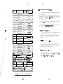
[ 1 I; General Description
The Formula-l, a l l - i n - o n e p o r t a b l e c o m p u t e r , i s d e v e l o p e d
for anyone who needs a complete business computer system at a
reasonable price, is miniaturized and lightened to be portable.
This computer is a high-performance and multi-purpose microcomputer system, c o n s i s t o f 2 d i s k d r i v e s o f 5 . 2 5 ” t w o - s i d e d
d o u b l e d e n s i t y ( a p p r o x i m a t e r e c o r d i n g c a p a c i t y i s 716K b y t e s
a f t e r F o r m a t ) , 5.5” CRT, Keyboard, Thermal Printer,
EP-ROM Programmer as well as Serial & Parallel I/O Interface,
all packed in one case.
Further., i t i s p o s s i b l e t o w r i t e - i n & r e a d - o u t E P - R O M s ,
and use for personal computing easily.
It is available as a
powerful software development tool and a complete business
computer system, i f a l i n e p r i n t e r , 8” f l o p p y d i s k d r i v e , e t c .
are being externally connected.
T h e F o r m u l a - l cses t h e C P / M - 8 0 V e r s i o n 2 . 2 a s a n
Operating System, t h e r e f o r e t h e s o f t w a r e d e v e l o p e d b y o t h e r
c o m p u t e r s y s t e m s o f d i f f e r e n t a r c h i t e c t u r e c a n k e e p mutualt r a n s f e r a b i l i t y , a s l o n g a s t h e y a r e b a s e d o n t h e CP/M-80
Operating System.
The CPU of this computer is 280A, which
enables high speed processing.
.
The memory of the Formula-l being equipped with RAM 64K
bytes along with Boot-Strap ROM 4K bytes.
RAM is 64K bits x 8
dynamic RAM and all of the 64K bytes memory spaces are used for
user-programmable area.
ROM is 4K bytes EP-ROM, used only for
Boot-Strap.
At the state of Boot-Strap the system program will
b e l o a d e d f r o m t h e 5.23” f l o p p y d i s k e t t e i n t o t h e m a i n m e m o r y .
l .* ;i.
*
Note :
CP/M i s a r e g i s t e r e d t r a d e m a r k o f D i g i t a l R e s e a r c h .
WordStar, CalcStar a n d I n f o S t a r a r e r e g i s t e r e d t r a d e m a r k s o f
MicroPro.
Other program name, system name, etc. are their original
trademarks of the each company.
Z80A i s a r e g i s t e r e d t r a d e m a r k o f Zilog I n c .
T h e u s e r c a n a c c e s s d i r e c t l y , d u e t o t h e I/O c o n t r o l
program, w h i c h h a s b e e n a l l o c a t e d i n t h e f i x e d a r e a .
Expansion floppy disk drive can be expanded to 2 units, either
by 5.25" or b y 8” f l o p p y d i s k d r i v e s . These devices can be
used as an external memory with a maximum capacity of 2M bytes
b y c o n n e c t i n g t w o 8 ” f l o p p y d i s k d r i v e s Df t w o - s i d e d d o u b l e
density.
The EP-ROM Programmeron the Formula-l can be operated in
conversational style with CRT and keyboard.
You can write-in
a n d r e a d - o u t 4 k i n d s o f E P - R O M s , w h i c h a r e a s follows:2716 (Intel) / 2516 (TI), 2732 (Intel), 2532 (TI) and
. 2764 (Intel).
Besides the 2 Serial I/O Ports of RS-232-C, 2 Parallel I/O
P o r t s o f 8-bits, B i g g e r C R T I n t e r f a c e a r e e q u i p p e d i n s t a n d a r d .
RS-232-C can use either Synchronous or Asynchronous mode (Start
Stop Synchronous).
In standard, both ports are Start Stop
Synchronous mode.
The Parallel I/O Ports are programmable and.
can designate I/O by bit-unit according to the program.
Usually, this port is used for an external printer.
You can
o n l y c o n n e c t d i r e c t l y , e x t e r n a l p r i n t e r w i t h C e n t r o n i c s StaniInterface.
Y o u c a n a l s o c o n n e c t a n e x t e r n a l b i g g e r C R T whit
being d r i v e n by composite video signal.
-iV-
-t-
e
-
[ 3 J System Features
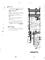
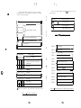
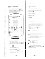
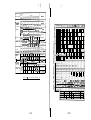
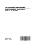
[ 21 System Architecture
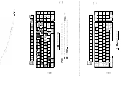
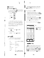
Following shows the block diagram of the Formula-l.
CPU
Z80A
r
i
1
BOOT-STRAP , MEMORY
RAM 64 K/B
ROM 4 K/B
1
,
,
t
’ KEY BOARD
DMAC
2808 DMA ’ CONTROLLER
CTC
Z80A CTC
80 COLUMNS
5” THERMAL
PRINTER
,
ml+
.
PRINTER
CONTROLLER
1.
The Z80A CPU operating at 4 MHz being used in the Formula-l.
2.
The main memory consist of 64K bits x 8 dynamic RAM, and
the memory capacity for the user’s programmable area being
64K b y t e s .
3.
This system is very reliable due we are using many kinds
of LSI and multi-layered PCB.
4.
As a result of using DMA, t h e d a t a t r a n s f e r i s i n h i g h
speed., a n d t h e b u r d e n o f t h e s o f t w a r e b e i n g d e c r e a s e d .
5.
The system’s CRT has semi-graphic function.
6.
Loaded with EP-ROM Programmer enables you to write-in and
read-out 4 kinds of EP-ROMs (2716/2516, 2732, 2532 and
2 7 6 4 ) o n t h e CP/M-80 b a s i s .
7.
All the necessary devices are packed in one case,
miniaturized and lightened to be portable sufficient
for data processing purposes.
8.
T h e CP/M-80 i s u s e d a s a n O p e r a t i n g S y s t e m o f t h e F o r m u l a - l .
9.
Various kinds of application software packages are available
o n t h e CP/M-80 b a s i s .
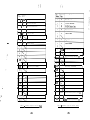
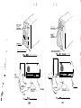
[ 4 ] Physical Characteristics
271612516,
2732,2532,
l
I
I
Dimensions
424(W) x 555(D) x 212(H) mm
Weight
15 kgs
Power Supply
ACllOVilOX, SO/BOHz o
Power Consumption
Maximum 2OOW
Fuse : ACllOV-2At
Environment
O p e r a t i n g t e m p e r a r a r e i s f r o m 5’ C t o 40' C.
I
2764
r
AC230V*lOX, 50/60Hz
G230V-1A
P r e s e r v a t i o n t e m p e r a t u r e i s f r o m -10’ C t o
55” c .
( B u t a d i s k e t t e i s f r o m 1 0 ” C t o SO0 C . )
Relative humidity (no dewdrops) i s f r o m 10%
to 90%.
("1
or *2 : Expansion Floppy Disk Drives)
F i g . 1 : Formula-l Hardware Block Diagram
’
p . *.
f5j -4
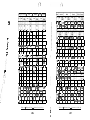
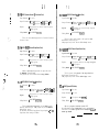
[ 5 ] Hardware Specifications
[q-r C P U
'.
i
.
.':
1. I'
'
CTC(Counter & Timer)
Device
Z80A CTC
Device
Z80A CPU (Clock: 4 MHz)
Channels
4 Channels (Channel #O - Channel #3)
Word Size
8 bits/byte
Clock
4 MHz at Timer Mode
Processing Method
8 bits parallel binary
Mode
Counter & Timer Mode
Commands
1-4 bytes/command, commands-158
C h a n n e l #O
8 bits Programmable Timer
C h a n n e l
[q-2 Memory
Device
ROM: EP- ROM 4K bytes
RAM: Dyn amic RAM
Use
64K
bytes (64K bits x 8)
Baud-Rate setting of Serial I/O Channel-A
#1
C h a n n e l #2
Baud-Rate setting of Serial I/O
C h a n n e l #3
8 bits Programmable Counter & Timer
Interruption
Break-out of Interruption Vector according
to demand of each channel
ROM: Initial Program Loader (IPL & X/O
Control Program)
* Zero Count
* Time Out
RAM: Main Memory o f 64 K bytes used for
user's progra mmab le area.
DMA Transfer
Channel-B
Memory to Memory, Memory to I/O
[d-5 Floppy Disk Drive
Type of Disk
($3 D M A
Device
Z80A DMA
Mode
Byte (cycle steal)
Functions
Data transfer between 2 Ports (I/O or
Memory), Search of 8 bits data
co mbin ation
& Burst Mode
of data transfer and data .
se arch between 2 Ports.
Channels
1 channel (2 Ports)
Use
Floppy disk drive
Serial I/O Port
Parallel I/O Port
5.25" two-sided double density x 2 units
Capacity
358K b y t e s / d i s k d r i v e
Data Bytes/Sector
1 2 8 bytes/sector(FM),256
Sectors/Track
18 sectors/track
Cylinders/Disk Drive
40 cylinders/disk drive
Tracks/Disk Drive
80 tracks/disk drive
Recording Method
FMIMFM
Recording
Interruption
Drive
Density
. Track Density
(Track 0, Side 0 -. FM method)
2938 BP1 (FM),
Rotational Speed
300 RPM
Break-Out of Interruption Vector according
Data Transfer Rate
12SK
Transfer Method
DMA Transfer
Average of Access Time
100 mS
Average of Seek Time
9 3 mS
bits/set
DMA'demand
End of data
transfer
Matching at data searching
-4-
5876 BP1 (MFM)
48 TPI
Memory
to conditions
bytes/sector(MFM)
(FK),
250K bits/sec(MFM)
.
!.
.
(51-7 Thermal Printer
Seek Time
6 mS
Settling Time
15 mS
Method
Thermal
Head Load Time
50 mS
Characters
80 columns/lines (maximum)
Motor Start Time
400 mS
English/Figures, Small Letters of
English, Marks - Total 96
Reserved capacity : 64
[5j-6 Video Display
f
Semi-graphic patterns - Total 96
CRT Size
5.5" (Green, non-glare coating),
95(H) x 70(V) mm
Characters
80 columns/line x 24 lines
Format
5 x 7 dot matrix : character mode
7 x 7 dot matrix : semi-graphic mode
Line Spacing
4.5 mm
English/Figures, Small Letters of
English, Marks - Total 96
Direction
Reserved capacity : 64
Character Generator
2K bytes, EP-ROE
Semi-graphic patterns - Total 96
Character Code
ASCII
Format
6 x 7 dot matrix : character mode
8 x 8 dot matrix : semi-graphic mode
Printing Width
103 mm
Paper
Cursor
Underline blinking (16 frames interval)
127(W) x 65(Dia.) mm roll paper
No. TP-5OCA127 by Jujo Seishi
Mode
Non-interlace mode
Method
Video RAM method (I/O map)
Video RAM Capacity
2K bytes, static RAM
Character Generator
2K bytes EP-ROM
Character Code
ASCII
Interface
TTL level (active logic), separate type
Expansion Interface
Composite video signal for bigger
CRT, l.SV P-P (Video: l.OV)
Gain
23 dB
Video Frequency
16 MHz
Horizontal
60 Hz (free run oscillator)
Vertical
Frequency
[5] -8 EP-ROM Programmer
EP-ROM
*
*
*
*
2716
2732
2532
2764
(Intel) / 2516 (TI)
(Intel)
(TI)
(Intel)
However,
* Video Signal
* Horizontal Synchronous Signal
* Vertical Synchronous Signal
Frequency
. From left to right
programming voltage for
271612516, 2732 is 25V and 2764 is 21V.
Programming Pulse
50 mS (Hardware Timer)
Selection of EP-ROM
Programmable
When using EP-ROM, you should adjust
the slide switch on the right of EP-ROM
socket UP or DOWN, according to specific
EP-ROM, you intend to use.
15.77 KHz (free run oscillator)
-60
-7-
Special-Keys
[q-Q Keyboard
Arrangement
Full-Keys (Conformed to ASCII format)
+ Numeric-Keys + Function-Keys
Code
ASCII Code
Shift Mode
Shift code of Full-Keys being output by
holding <SHIFT> k e y down and press Data-Keys
a t t h e s a m e time.
Control Mode
C o n t r o l c o d e 01(H)-lA(H) b e i n g o u t p u t b y
h o l d i n g <CTRL> k e y d o w n a n d p r e s s D a t a - K e y s
a t t h e s a m e time.
Function-Keys
* Fl , FZ , F3 , F4 e FS ) F6 s F7 ) F8 B F9
+ RESET : S y s t e m - R e s e t k e y .
The system is set at initial state by
holding <CTRL> key down and press <RESET>
key at the same time.
+ FEED : R o l l P a p e r F e e d K e y .
Roll paper is fed by hitting this key.
* CAP LOCK : Capstan Lock Key.
By locking this key, alphabet is changed
from lower case to upper case.
= SHIFT LOCK : Shift Lock K e y .
By locking this key, full keys are changed
to shift mode.
I
These key codes are assigned 8 bytes by
‘FUNC’ command of System Utility Program.
* HOME , - , - ,
t
#
1
Hardware Scanning
Inter Lock
N-Key roll over
Character Generator 2K bytes, EP-ROM
These cursor control key codes are assigned
2 bytes by ‘FUNC’ command of System Utility
Program.
At the first time these key codes are
initialized as follows.
Switches
Momentary & Alternate, Mechanical contact
Chattering
L e s s t h a n 5 mS
‘H’
Key Top
Step sculpture type
<ESC> ‘C’
Letters
W i t h l e g e n d (doubl#e:-shot
Numbers of Key
91 keys
<ES0
<ESC>
Numeric-Keys
Scanning Method
‘D’
t
<ESC> ‘ A ’
5
<ESC> ‘ B ’
These keys can be programmed as
Keys if you do not intend to use
The codes are assigned 2
entry.
‘FUNC’ command of System Utility
-8-
I
molding)
I
The Keyboard layout is on the following page.
Functionfor numeric
bytes by
Program.
/
i
/
1
t
-g-
’
f5J -10
Serial I/O Ports
Z8OA SIO
Device
* Asynchronous (Start Stop Synchronous)
* Synchronous
* HDLC/SDLC
Channels
2 Channels (Channel-A, Channel-B)
Baud-Rate Clock
CTC (Programmable)
Baud-Rate
* Asynchronous mode
150, 300, 600, 1200, 2400, 4800,
1 9 2 0 0 BPS
.
* Synchronous mode
300, 600, 1200, 2400, 4800,
3 8 4 0 0 BPS
9600,
9600, 19200,
Set by DIP-Switches, each channel
independently.
Interface
* Channel-A : RS-232-C
+ C h a n n e l - B : RS-232-C or 20mA Current-Loop
DMA
When Transmitting/Receiving buffer is at
I t fs p o s s i b l e t o
state of readiness.
input to CPU, DMA transfer request by
specific program.
Interruption
B r e a k - O u t of Interrur+tion V e c t o r b y t h e
f o l l o w i n g condition,an are o n l y p o s s i b l e w i t h
specific program.
*
*
+
*
Transmitting buffer is empty.
Receiving character is valid.
Change of status
Break-out errors (Parity, Over Run,
Framing, End of Frame)
[5l-11 Parallel l/O Ports
Device
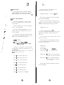
[ 6 ] Expansion Interface Specifications
280A P I 0
*
*
*
*r
*
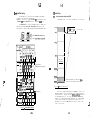
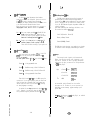
The Formula-l’s Expansion Interface Specifications are
Byte output mode
Byte input mode
Byte bi-directional mode (only Port-A)
Bit mode
Port
8 bits x 2 ports (Port-A, Port-B)
Handshake Line
2 lines each port (Ready, Strobe)
Interface
TTL level (Using Centronics Standard
Interface as our standard.)
DMA
The DMA transfer requests Break-Out by the in
coming ‘DMAREQ signal from outside the
system unit. Therefore, i t i s p o s s i b l e t o
input to CPU, DMA transfer requests by
specific program.
Interruption
Break-Out of Interruption Vector by
.
as follows.
* 5 . 2 5 ” f l o p p y d i s k d r i v e s (FD-5)
* 8” floppy disk drives (FD-8)
* Centronics Standard Interface Printer (FP-80)
* RS-232-C Serial Interface
* 20mA Current-Loop Serial Interface
* Bigger CRT which is driven by composite video signal. (FM-g)
By using connectors on the rear side, expansion devices
can be connected directly. Further, Baud-Rate of Serial Ports
and Jumper can be set respectively.
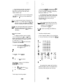
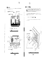
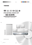
The layout of the rear view is as follows.
0
the
following conditions are only possible with
specific program.
0
RS-2320C(CH-8)
* Receiving strobe signal from the external
devices at the byte output mode.
* Receiving strobe signal from the external
devices at the byte input mode.
* Receiving strobe signal (for input or
output) from the external devices at the
byte bi-directional mode.
* When the conditions are true at the state
of bit mode.
Parallel I/O
Connector
Connector'
8” Floppy Disk
J
Drive Connector
\ Fuse
Power Switch
5.25” Floppy Dis
Drive Connector J
FIR. 3 : R e a r V i e w o f the F o r m u l a - l
-120
AC Connector
-t3-
/\ %7
/
1\
[5j-11 Parallel I/O Ports
Device
[ 6 ] Expansion Interface Specifications
Z80A PI0
The Formula-l’s Expansion Interface Specifications are
as follows.
* Byte output mode
* Byte input mode
* Byte bi-directional mode (only Port-A)
* 5.25” floppy disk drive8 (FD-3)
* 8” f l o p p y d i s k d r i v e s (FD-8)
* C e n t r o n i c s S t a n d a r d I n t e r f a c e P r i n t e r (FP-80)
* RS-232-C Serfal Interface
* 20mA Current-Loop Serial Interface
* Bigger CRT which is driven by composite video signal. (FM-g)
+- Bit mode
:
,:.
,
* I’
I
., .t .
.,;c”
Port
8 bits x 2 ports (Port-A, Port-B)
Handshake Line
2 lines each port (Ready, Strobe)
Interface
TTL l e v e l ( U s i n g C e n t r o n i c s S t a n d a r d
DMA
The DMA transfer requests Break-Out by the in
By using connectors on the rear aide, expansion devices
c a n b e c o n n e c t e d d i r e c t l y . Further, Baud-Rate of Serial Ports
and Jumper can be set respectively.
The layout of the rear view is as follows.
Interface as our standard.)
c o m i n g ‘m s i g n a l f r o m o u t s i d e t h e
Therefore, it i s p o s s i b l e t o
system unit.
input to CPU, DMA transfer requests by
specific program.
Interruption
Break-Out of Interruption Vector by the
following conditions are only possible with
Fan.
specific program.
/O
0
RS-232~C(CH-B)
Cormstor
* Receiving strobe signal from the external
devices at the byte output mode.
+ Receiving strobe signal from the external
devices at the byte input mode.
L’
r‘.
.
_-
-
Parallel I/O
Connector
Connector
* Receiving strobe signal (for input or
output) from the external devices at the
byte bi-directional mode.
8” Floppy Disu
Drive Connector
.
* When the conditions are true at the state
of bit mode.
Jumper, Baud-RatA
\Fuse
Power Switch
5.25” Floppy Dis
Drive Connector J
F i g . 3 : Rear View of the Formula-l
-12-
F
.
AC Connector
-130
[6]-1
5.25” Expansion Floppy Disk Drives (FD-5)
[6]-2
6” Expansion Floppy Disk Drives (FD-8)
The Formula-l can be expanded to 2 disk drives by the same
In this case,
specification as the system floppy disk drive.
remove the terminator from the expansion floppy disk drives.
A l l o c a t e ‘#2’, ‘#3’ t o p h y s i c a l d i s k d r i v e a d d r e s s b e c a u s e s y s t e m
d i s k d r i v e h a s b e e n s e t u p o n ‘tO’,‘#l’.
The Formula-l can be expanded to 2 disk drives (8”) of t h e
following specification.
I n t h i s c a s e , remove the terminator
from the expansion floppy disk drive.
A l l o c a t e ‘#2’,‘#3’ t o
physical disk drive address because system disk drive has been
a s s i g n e d t o ‘#O’,‘#l’.
See the item No. < (51-5 F l o p p y D i s k D r i v e > a b o u t t h e
Pertaining to the pin
specification of 5.25” floppy disk drive.
assignment of connectors and the signal name, refer to below table.
The pin assignment and the signal name are on the following
page < Table 2 : C o n n e c t o r S i g n a l o f 8 ” F l o p p y D i s k D r i v e >.
1
-- - I
9
11
w
Signal Ground
I
I Signal Ground
I
I
S i g n a l Ground
13
S i g n a l Ground
15
S i g n a l Ground
I
12
’
1
14
17
Signal Ground
-~~
19
S i g n a l Ground
20
21
S i g n a l Ground
22
Tracks/Disk Drive
I54 t r a c k s / d i s k d r i v e
Recording Method
FM/MFM
DRrVE
Recording Density
3 4 0 8 BPI(FM),
DRIVE
Track Density
48 TPI
Rotational
360 RPM
DRIVE
I
I
I
I
27
Speed
Signal Ground
29
I
Signal Ground
31
I
Signal Ground
I
Signal Ground
WRITE DATA
26
I
2 5 0 K b i t s / s e c ( F M ) , SOOK b i t s / s e c ( M F M )
1
Average of Access Time
8 3 mS
I
Average of Seek Time
9 1 mS
Seek Time
3 mS
Settling Time
15 mS
Head Load Time
50 mS
I
BRITE GATti
8
TRACK
,
I
1 WRITE PROTECT 1
28
30
I
I
32
I
I
34
1
*AD
DAm
SIDE SELECT
DRIVE
READY
I
I
I
T a b l e 1 : C o n n e c t o r S i g n a l o f 5 25” F l o p p y D i s k D r i v e
l
6816 BPI(MFM)
Data Transfer Rate
I
1
24
Signal Ground
I
33
brR-
I
Signal Ground
23
25
I
I
128 bytes/sector (FM)
256 bytes/sector ( M F M )
Bytes/Sector
~~
1
L
I
Data
77 cylinders/disk drive
RON
18
997K b y t e s
Cylinders/Disk Drive
16
-1
Capacity
26 sectors/track
1
I
8” two-sided double density
Sectors/Track
I INDEX PULSE
50
T y p e of D i s k .Drive
.
f
Signal
name
Pin
number
Pin
number
,
1
Signal
name
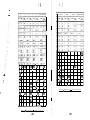
[6] -3
Centronics Standard Printer Interface (FP-60)
In a standard specification of the Formula-l, Parallel I/O
Port can be connected with the Centronics Standard Interface
Printer directly.
As pin assignment of the Parallel I/O connector has no full
c o m p a t i b i l i t y t o t h e C e n t r o n i c s Standarti P r i n t e r S p e c i f i c a t i o n ,
f o r d e t a i l s r e f e r t o < T a b l e 4 : Cable Connection for External
P r i n t e r >.
The logic of Parallel I/O Ports are shown in the following
page < Fig. 4 : L o g i c o f P a r a l l e l I / O P o r t s > .
Besides the other signals, the Parallel I/O Ports possess,
t h e s i g n a l s o f ‘Dm!?‘, ‘m’, ‘m’.
The explanation of these signals are as follows.
1.
’ .*
20
INDEX PULSE
Signal Ground
21
S i g n a l Ground
22
DRIVE READY
23
25
S i g n a l Ground
24
26
b
DRIVE 0
I
I
This
s i g n a l i s a c t i v e ‘ L o w ’ , and available when using
Parallel I/O for DMA transfer. U s i n g t h i s s i g n a l , i t i s
necessary to set up the parameter in the DMA c o n t r o l l e r .
This signal is connected to the ‘RDY’ terminal of DMA
controller.
. I
19
m ( D M A REQuest) - I n p u t
2
. COUNT
- (DMA transfer COUNT) - Output
This signal is active ‘Low’ and programmable, and when
the number of byte of DMA transfer reaches a set value, a
pulse signal is output.
T h e r e a f t e r , e v e r y 2 5 6 b y t e s of
data transfer one pulse being output.
3.
I
35
I
37
I
I
36
Signal Ground
I
Signal Ground
I
38
1
WRITE
I
DATA
I
39
I
Signal Ground
I
40
1 W R I T E GAm
I
41
I
Signal Ground
I
42
I
I
43
Signal Ground
I
1
44
WRITE PROTECT
45
Signal Ground
46
READ DATA
I -- 4’1
1
STEP
I
49
48 I
I
-
-
-
-
-
-
-
I
!j”
-
TRACK
-
-
O0
-
-
-
-
I
I------
I
T a b l e 2 : Connector Signal of 8’ Floppy Disk Drive
-t6-
BXTCLR (EXTernal C L O C K ) - I n p u t
This signal is active ‘Low’, and it is the input signal
o f t h e E x t e r n a l C l o c k a t t h e t i m e o f -using t h e C h a n n e l #3 o n
‘ C o u n t e r M o d e ’ o f Z80A C T C .
See < Fig. 5 : L o g i c of. C o u n t e r & T-lEer > .
+5v m8
lKnx0
- - - -
1
,P3a
PD5
,2'7/
Dnd
I;
(SN75452)f
=----rrrTl-i-lIr
y7
A4 '
#
1
,
I
I
I
I
'.PD3
A3
N3b
d
2, 74
,5$iLL--x &PI33
IYL
(SN75452)
A2}+1w-w----7.!PD1
N3a
J
5
8 ,PDO
(SN75452)'I
1 2'
l 9
N2b
3
ARDY r
bi (SN75452)
I
A5 t
+v
+5v
Z80A
PI0
3M 7
lmx8
--------
CHANNEL-A
BAUD-RATE CLOCK
K/TO1
CK/TGl
CHANNEL-B
BAUD-RATE CLOCK
ZC/T02
CK/TGZ
-Z80A
CTC
1.2288MHz/153.6KHz
ACK
B7
B6
<COUNTER CLOCK 1
1.2288MHz/153.6KHz <COUNTER CLOCK 2
BUSY
CK/TGO
ZC/TOO
B5
B4
1
83
82
M2b
3
v5
,
17
18,
I
A
CK/TG3
<CTCCLK
(Blank)
----I----------3
Bl
BO
BRDY
I
-1 (SN75452)l
I II
BSTB
Fig. 5 : Logic of Counter & TJmer
HaEQ
TRT > 23
-
--
YY” I
>
1-G
CTCCLK
Fig. 4 : Loaic of Parallel I/O Ports
I
I
231
I
1
I
1
2
i
Printing Data
I PD7
~ 7-~_
Printing Data
PD6
3
!
I
I-- ~
4
Contents
Signal
Name
Pin
Number
PDS
I PD4
r
I
OUT
I
OUT
PIOA7 ~ I
PIOA6
OUT
PIOAS
5 1 vrinting
Data
I
Formula-l
Signal
Name
II Printer
II
1
20
STROBE
:
I
2
8
DATA1
3
7
I DATA2
6
5
I
OUT
I
PIOA4
I
I
I
I
OUT
I
PIOA3
I
I
Printing Data
Printing Data
I
Remarks
Signal
Direction
Printer
I
4
I
I
I
6
19
I
20
II2
1
I DATA3
5
I DATA4
4
DATA5
11
SC:
11
SG
I
11
1
SG
I
II
22
I
11
I
SG
I
II
23
I
11
I
SG
I
24
11
SG
t
EI
7
I
8
.
:i
q
10
11
1
12
I
13
14
.I
I
15
ASTB
PLO-A Strobe
bSTs
IN
31
I
9
*
I
10
I
I
11
Signal Ground
SG
SG
I ~~-
I
ACK
1 BUSY
I PEMP
1
Signal Ground
End of Operation
IN
PIOB7
Under Operation
IN
PIOB6
p
of
Paper
1
16 1 r[ -Printer Ready
.t
-; .
I
.
IN
[
PIOB5
IN
1
PIOB4
Unused
PIOB3
Unused
PIOBZ
1 Reset
I
OUT
1
PIOBl
I
PIOBO
I
BRDY
I
I 21. I lsRDP
I
I
I
PIO-B Ready
22 1 ~~Pi0-B Strobe
23
r
I
24
25
m
DHAREV
I- 1
I
1
OUT
IN
-rssTB
)
I,
1
I *
+
m
*
DMA Transfer Demand
OUT
m
=
IN
11
12
1
SG
I
1
I DATA8
II
27
I
12
I
I1
13
I AcR-
II
28
I BUSY
29
I
I
I
4
15
I PEHP
II
30
I
16
II
3f
I
I
I
SC
I
12
I
SG
I
12
I
SG
I
12
I
SG
I
I
S G - Signal Ground
3m
-1 --EXTCLE 1 +
I
30 RMxx Insulated Flexible Cables
tI
\DB-25P
\ 57-30360
Side
of the Formula-1
Table 4 : Cable Connection for External Printer
Table 3 : Connector Signal of Parallel X/O
i
.
-21-
-4
I
j -121
6
'
P
I
1
/
I
Do not connect (*) signed pins, when using
Centronics Standard Interface Printer.
-2o-
2
I
D.ATA7
SiGe of the Printer
Note :
25
2
I
OUT
I
DATA6
36
DMA Transfer Count
CTC External Clock
13
1
1
+
Data Strobe
12
3
! :
I
:
[6] 4
RS-232-C Inter face
RS-232-C
Cl+A
.
In standard specification, 2 Serial I/O Ports of ‘RS-232-C’
28OA S I O b e i n g u s e d a s t h e
are equipped with the Formula-l.
F o r d e t a i l s p e c i f i c a t i o n s , refer to the item No.
controller.
< [5]-10 S e r i a l I/O P o r t s >.
RxDA
CTTSA
DCDA
Channel-A is exclusive for ‘RS-232-C’. The ‘RS-232-C’ and
‘20mA Current-Loop’ of Channel-B can be changed by replacing the
short plugs on the rear side of this computer.
For setting procedure of the short plugs, see the item No.
< [8] J u m p e r S e t t i n g > .
TxDA
TSA
mm
\
; RD
1 cs
' CD
1
75154 ’
SG
-12v ’
I
2;
24 ,’
17.
15
Further, i t i s p o s s i b l e t o s e t t h e B a u d - R a t e f o r e a c h
For detail see the item No.
channel independently.
< [9] B a u d - R a t e S e t t i n g > .
RS
ER
ST-1
RT
ST-2
You can refer to < Fig. 6 : L o g i c o f S e r i a l I / O P o r t s >
About the
which shows the circuit of the Serial I/O Ports.
pin assignment of the connector and the signal name, see
< Table 5 & 6 : C o n n e c t o r S i g n a l o f R S - 2 3 2 - C (CH-A),(CH-B) >.
Z80A
sxo
[6]-5 Bigger CRT Interface (FM-g)
..
Composite Video Signal Interface is equipped in standard.
If you want to use bigger CRT, y o u c a n c o n n e c t c o m p o s i t e v i d e o
monitor to the rear side connector ‘BNC’.
RTSB
TxDB
.
DCDB
CTSB .
RxDB .
d
b
’
2 33
-a( JP5
-3
.
* 8XD
E
I
I
: ilcs
fClCA
LbLSO4
CHANNEL-A
BAUD-RATE
CLOCK
CHANNEL-B
BAUD-RATE
CLOCK
SDCLPP
‘P8 4
R
188
2SC372G
Fig.
-220
6
: L o g i c o f S e r i a l I/O P o r t s
-230
I
Signal
Pin
' Number IN a m e
c
I
1
I
2
I
3
I
4
I
Remarks
I
I
I
FG
1 Frame Ground
I
SD
1 RS-232-C Send Data
I
1
RD
f RS-232-C Receive Data
I
1
RS
1 Request to Send
I
I
I
5
I
CS
I
Clear to Send
7
I
SG
I
Signal Ground
I
CD
1 Carrier Detect
8
I
h
RDCLPP 1 20mA Current-Loop Receive Data (t)
10
11
I
l3
T--
~~
-~
I\l
I
12
I
15
1 SDCLPP 1
20mA Current-Loop Send Data (t)
I
I
~~~
14
I
15
ST-2
, Send Timing (From MODEM)
I
ST-2
I
Send Timing (From MODEM)
-1
\
17
RT
I
Receive Timing
17
I
RT
Receive Timing
L
L
18
19
ER
Data Terminal Ready
L
3
l
J
Ic
,
I
21
,
22
.
I
ST1
22
23
23
~ ~~
-- ~
24
21
1 Send Timing (To MODEM)
4
I
I
1
I
b
Table 5 : Connector Signal of RS-232-C (CH-Al
-24-
24
25
RDCLPM
II
I
ST1
20mA Current-Loop Receive Data (0)
1
I
I
1 SDCLPM 1
I
Send Timing (To MODEM)
I
I
.I
20mA Current-Loop Send Data (0)
I
I
J
Table 6 : Connector Signal of RS-232-C (CH-B)
-250
[ 7) -2
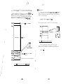
[ 71 Expansion Device Connection
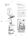
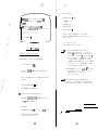
(7)-l
FD-5 & FD-8 Floppy Disk Drives Connection
You can connect with the Formula-l maximum 2 units of
Expansion Disk Drives, d e t a i l s a r e a s f o l l o w s : -
FM-9 Bigger CRT Connection
(1) 5.25” Disk Drive (double density) x 2 units (FD-5)
(2) 8” Disk Drive (single density) x 2 units (FD-8)
(3) 8’ Disk Drive (double density) x 2 units (FD-8)
Our FD-5 (5.25’) and FD-8 (8’) disk drives are two units of
t w o s i d e d d o u b l e d e n s i t y d i s k d r i v e s . T h e r e f o r e , you can u s e
single density (8” only) as well as double density diskettes as
per your requirement.
F o r y o u r i n f o r m a t i o n , when using FD-5 or FD-8 with
Formula-l you do not need to set physical address.
The terminator has already been detached from the disk drives.
Because this is being set as per our company’s standard
peripherals to use simultaneously with Formula-l.
However, you may have to refer < Table 7 : Expansion
Floppy Disk Drives Address > time to time to use different
diskettes due logical address (drive name) being assigned
separately for each drives.
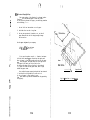
Power Switch ON/OFF
Briqhtness Control Knob
/Contrast Control Knob_
Fig. 7 : FM-9 Bigger CRT
Type of
diskette I
..
two-sided
double density
5.25”
8”
Physical
address
Description
DS2
I
DS2
E
one-sided
single density
1 DS3
F
DS2
G
two-sided
double density
I
: FM-9 Cable Connection
-260
DS3
I
1
H
Table 7 : Expansion Floppy Disk Drives Address
Connector
8
c
one-sided
single density
AC Power
Fig.
’
two-sided
double density
two-sided
’
II d o u b l e d e n s i t y ,
BNC
Logical
address
I
-27-
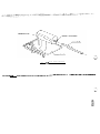
Diskette
Disk Drive
"In Use"
Power Switch ON/OFF/
FIR. 11 t FD-8 Floppy Disk Drive
FOR. 9 : FD-5 Floppy Disk Drive
.
0
,’
0
O\
r Q0
r 0
”
: .
Gray
Color
fH\ ’
\
;
I)
\ AC Power
‘.
i
*
t
Y
:r,
.
w
.
I
(Note 1)
(Note 1)
Ffg. 10 : FD-5 Cable Connection
-280
Fig. 12 : FD-8 Cable Connection
-29-
,
ti
f *
4:
,-.
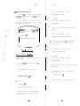
Note 1 :
FD-5 a n d F D - 8 d i s k d r i v e s f l a t c a b l e c o n n e c t o r ’ s m a r k s
indicates to insert by matching with appropriate marks
of the connecting sockets,
I71 -3
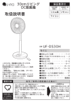
FP-80 External Printer Connection
.
Note 2 :
Be careful not to use FD-5
time
and FD-8 together in the
same
l
Roller Knob
Due there being no exhaust fan in the disk drives (FD-5,
therefore to refrain from over heating you should
put it ‘OFF’ when not using.
FD-8),
not put anything (paper, books, heavy manuals,
diskettes etc.) on the drives, i n o r d e r t o h a v e p r o p e r
ventilation.
Do
Fig. 1 3 : F P - 8 0 E x t e r n a l P r i n t e r
Parallel I/O
Connector
a\AC Power
Printer Connector
FOR. 14 : FP-80 Cable Connection
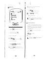
f 81 Jumper Setting
JP8
T h i s c o m p u t e r h a s e i g h t j u m p e r s f o r s e t t i n g , f r o m JPl t o
JP8. I t i s p o s s i b l e t o s e t t h e j u m p e r s b y p u t t i n g s h o r t p l u g s
on the jumper posts, w h i c h a r e o n t h e r e a r s i d e o f F o r m u l a - L
T h e r o l e o f e a c h j u m p e r s a r e o n the following page.
JP6
3
JP3
JP2
JPZ
JP7
Y
.
~~
2
!
I
JP2
Contents
Remarks
I
l-2
Used Ext. Clock as Receiving Clock
SIO Channel-A
3
Used Int. Clock as Receiving Clock
SXO C h a n n e l - A *
1-2
Used Int. Clock as Transmitting Clock
SIO Channel-A B
2-3
Used Ext. Clock as Transmitting Clock
SIO Channel-A
’
r
I
1-2
I Used Ext. Clock as Receiving Clock
I 2-3 I Used
1 SIO Channel-B
1 SIO Channel-B
*
1-2 Used Int. Clock as Transmitting Clock 1, SIO
Channel-B
I
I
2-3 Used Ext. Clock as Transmitting Clock i SIO Channel-B
*
Xnt. Clock as Receiving Clock
L
JP4
/
bJP3
RS-232-C
1-2
’
2-3 20 mA Current-Loop
JP6
SIO Channel-B *
SIO Channel-B
l-2
Used Counter Output of Channel #O
as a Clock Input of CTC Channel #3
CR Channel #3
(Counter Mode)
2-3
Used Ext. Clock as a Clock Input
of CTC Channel 83
CTC Channel 83 *
(Counter Mode)
b
Channel-B
(Receiving)
I SIO
I
SXO C h a n n e l - B *
I (Receiving)
I
l-2 20 mA Current-Loop
Non-Voltage Type
JP8
.
l-3 20 mA Current-Loop
’ 2-4 Voltage Type
t
I
SIO Channel-B
(Transmitting)
Note :
, SIO, Channel-B *
(Transmitting)
P e r o u r s t a n d a r d , jumpers being already set a s s h o w n
b y t h e (*) s i g n s . Y o u c a n a l s o s e t j u m p e r s a s p e r y o u r
s p e c i f i c u s e . However, i n each jumper you n e e d to set
o n l y o n e p a i r of p i n s . Example:- f o r s e t t i n g 3Pl
e i t h e r y o u s e t (l-2) o r ( 2 - 3 ) p i n s .
Table 8 : Jumper Setting
R ‘.
f
?
.i
r’; ‘* 4
2
p
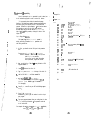
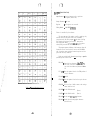
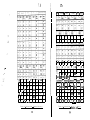
[ Q] Baud-Rate Setting
[lOI Initial Start
IW
The Baud-Rate of Serial I/O Ports can be set for each
Channel-A and Channel-B independently.
Baud-Rate is formed by using ‘ C h a n n e l il ( f o r C h a n n e l - A ) ’ a n d .
‘Channel #2 (for Channel-B)’ of this computer’s Z80A CTC.
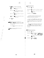
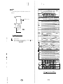
Memory Allocation and Boot-Strap ROM
The following shows
the
The Baud-Rate is set by the DIP-Switch on the rear side.
When you intend to change the Baud-Rate, never fail to do
System-Reset, otherwise the changed Baud-Rate can not be set.
---. -.
I
-4
memory
allocation of
the
I4'
Formula-l.
4K bytes
IPL & System I/O
Control Program
I
Boot-Strap ROM
Channel-A Channel-B
300
8000~
IIOFF) ON 1 ON 1 OFF 1 ON
.
600
.
i
.
I
I
64K bytes
Main Memory
2400
11 ON 1 ON 1 OFF 1 OFF 1 ON
4800
1) OFF 1 ON 1 OFF 1 OFF
9600
ON OFF OFF OFF ON
19200
OFF OFF OFF OFF ON
300
11 ON 1 ON 1 ON
Asynchronous
(Start Stop Synchronous)
1 OFF
I
1200
I
2400 IIOFFIOFF\ ON ION 1 OFF 1
1
19200
38400
4
FF’FFH
IOFF
1
11 ON
OFF
ON ( OFF 1 ON
1 OFF
ON 1 OFF1 ON
1 OFF
(1 ON ( OFF ( OFF ( ON 1 OFF
h.
OFF OFF OFF ON
1
OFF
a
: When IPL operates, t h e c o n t e n t s o f BootStrap ROM are transferred in this area.
Fig. 15 : Memory Allocation
* Synchronous
4800
9600
I
I~~]oN 10~4
COOOH
FsooH
600 IIOFFION ) ON ION 1 OFF 1
110~
8
I
Only when setting the Power-ON or the system is reset, the
Boot-Strap ROM becomes at readable state, thereby overlapped
with main memory.
D u r i n g t h i s t i m e , 0000(H)-OFFF(H) a d d r e s s o f
the main memory being at the state of "Write" only, and CPU
executes the program in Boot-Strap ROM,
By the output of ROM
disable signal according to the program, Boot-Strap ROM is
parted from the system, a n d a l l o f m a i n m e m o r y t u r n s t o t h e
state of read/write.
T a b l e 9 : Baud-Rate Settinq
-349
-350
m
‘
1
II
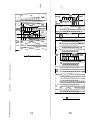
I n s t a n d a r d d e s i g n , IPL, I/O Control Program, Expansion
D e v i c e C o n t r o l P r o g r a m , e t c . , are stored in the Boot-Strap ROM.
A f t e r t r a n s f e r r i n g t h e p r o g r a m t o t h e a d d r e s s F500(H)FFFF(H) of the main memory, t h e p r o g r a m j u m p s t o I P L i n t h i s
a r e a , thereafter Boot-Strap ROM is parted from the system at
the Power-ON or System-Reset. The following shows the memory
a l l o c a t i o n o f t h e F o r m u l a - l w h e n u s i n g t h e ‘6OK CP/M-80’.
System Area
(101-2 System Start
3
2 5 6 b y t e s : System Parameter
When you set the Power-ON or System-Reset, the IPL program
starts immediately. The following message will appear on your
CRT and the Boot-Strap program being loaded to the main memory
from the system diskette.
F o r m u l a - l I P L V e r s . *.* f o r m i n i 2D
The Boot-Strap program is loaded to the following address.
System Diskette
:
01
(Side
Track
: 0
Sector : 1 J
02OOH
User’s Area
53K b y t e s
t
Fig,
17
: Boot-Strap Program Allocation
When the Boot-Strap program is loaded, if an error
o c c u r s , the following message will appear on your CRT,
and the process of loading to the main memory restarts again.
D400~
KooH
CCP Area
.-m-m-----m--- - -a - - BDOS Area
----)----I----------.
BIOS Area
--“------------L-II-I/O Control Area
IPL error !
CP/M-80 t Loaded from a System
Diskette
Transferred from the Boot-Strap ROM
FFFFH
F i g . 1 6 : M e m o r y A l l o c a t i o n U s i n g 60K CP/M-80
-36-
I
1
When the Boot-Strap program is loaded correctly, the
following message appears on your C R T , t h e r e a f t e r t h e s y s t e m
program is loaded into the main memory from the system diskette.
I n c a s e o f u s i n g t h e CP/M-80, t h e s y s t e m p r o g r a m i s l o a d e d i n t o
D400(H)-FlFF(H) a d d r e s s e s .
See < Fig. 16 : M e m o r y A l l o c a t i o n U s i n g 6OK CP/M-80 >
[ll ] Software Specifications
[II] -1
T h e F o r m u l a - l u s e s t h e CP/M-80 V e r s i o n 2 . 2 w h i c h i s
evaluated as the standard Operating System of 8 bits microcomputer in the world.
CP/M B o o t V e r . *.* f o r rinl 2 D
This Operating System can operate application programs and
p r o c e s s d a t a w i t h o u t d i f f i c u l t y b e c a u s e o f i t s s u p e r i o r multipurposed feature and excellent operating ability.
For this
reason, even the software developed for other computer systems
of different architecture can keep mutual-transferability, as
long as they are based on the CP/M-80 Operating System.
Therefore, old libraries as well as know-hows already filed-in
can be used easily.
Then, i f a n e r r o r o c c u r s , t h e f o l l o w i n g m e s s a g e w i l l
appear on your CRT, a n d t h e p r o c e s s o f l o a d i n g t o t h e m a i n
memory restarts again.
Boot err.
When the Boot-Strap program is loaded correctly, the
following message appears on your CRT, and the CP/M-80
starts automatically.
,
*+* 6 0 K CP/M V e r s . 2 . 2 F o r m u l a - l S y s t e m *+*
BIOS Created By YCU Co., Ltd. (1983.**~*“)
*‘- Cursor
Operating System
I
See the ‘CP/M-80 OPERATING SYSTEM MANUAL’ for details of
the CP/M-80 commands.
The Formula-l can use various kinds of
a p p l i c a t i o n s o f t w a r e p a c k a g e s o n t h e CP/M-80 b a s i s a v a i l a b l e o n
the market.
The CP/M-80 is a standard Disk Operating System for the microcomputer.
The CP/M-80 system is composed of CCP to process a command,
BDOS to manage access of the file, BIOS to control the I/O
d e v i c e w h i c h a u s e r u s e s , and TPA of the memory area in which a
user’s program is allocated.
T h e CP/M-80 s y s t e m i s a F D O S , i n w h i c h t h e s e q u e n t i a l
processing is main.
Which reads out the file and executes when
a command being input by the console and it corresponds to a
program name.
U s i n g t h e W/M-80 S y s t e m F u n c t i o n s , a l o n g w i t h
a user’s program, a user can easily actualize the data transfer
w i t h I / O d e v i c e , t h e m a n a g e m e n t o f t h e d a t a f i l e i n t h e *floppy
disk drive, etc.
F o r d e t a i l m e m o r y a l l o c a t i o n t o u s e w i t h t h e CP/M-80
Operating System see the item No. < [lo]-1 M e m o r y A l l o c a t i o n
and Boot-Strap ROM >.
T h e r e a r e t w o k i n d s o f c o m m a n d s i n t h e CF/M-80. .One i s b u i l t - i n
command, a n d t h e o t h e r i s a t r a n s i e n t c o m m a n d .
The transient
command being loaded into the memory from the diskette.
-390
The following is built-in commands of the
1
i
1
‘.
;.
ERA
Erase specified files.
DIR
List file names in the directory.
REN
Rename the specified file.
SAVE
Save memory contents in
TYPE
T y p e t h e c o n t e n t s o f a f i l e o n t h e logsed d i s k .
a
[ill-2 CP/M-80 System Functions
CP/M-80.
T h e CP/M-80 h a s 3 9 k i n d s o f s y s t e m f u n c t i o n s .
The user
can set necessary parameters in the register or in the buffer,
a n d c a l l s t h e B D O S o f t h e CP/M-80.
So inside the BDOS, the job
being executed by the given parameter, and the state being
returned to the user’s program automatically.
The operations
are generally divided into two classes. One is for the I/O
device, the other is for the disk operation.
file.
Following are the I/O Device Operation.
I
1..
!
! .
T h e f o l l o w i n g i s t r a n s i e n t c o m m a n d s o f t h e CP/M-80.
STAT
ASM
LOAD
DDT
PIP
ED
SUBMIT
DUMP
MOVCPM
XSUB
FORMAT
FSYSGEN
SYSTEM
PROMW
FUNC
*
*
*
*
It
1.
Read a Console Character
I
2.
Write a Console Character
I
3.
Read a Sequential Tape Character
4.
Write a Sequential Tape Character
5.
Write a List Device Character
6.
Get or Set I/O Status
7.
Print Console Buffer
8.
Read Console Buffer
9.
Interrogate Console Ready
The FDOS operations that perform disk I/O a r e .
P l e a s e r e f e r t o o u r ‘CP/M-80 OPERATING SYSTEM MANUAL' for
detail of the above commands.
Details for the commands with (*) sign are available In this
manual.
1.
Disk System Reset
2.
Drive
3.
File Creation
4.
File Open
5.
File Close
6.
Directory Search
7.
File Delete
8.
File Rename
9.
Random or Sequential Read
10.
-4o-
Selection
Random or Sequential Write
-41-
.:
i*
; I
I (
I
11.
Interrogate A v a i l a b l e D i s k s
12.
Interrogate Selected Disk
13.
Set DMA Address
14.
S e t / R e s e t F i l e Xndlcators
Device Allocation
The following 4 logical devices are allocated in
t h e CP/M-80.
!
I
”
:,.
[II) -3
CON : The System Console Device
RDR : The Paper Tape Reader Device
CP/M-80 functions and their numbers are listed below.
PUN : The Paper Tape Puncher Device
LST : The
.*
.*
,’
48
: .
!
; ..‘
:
I
.
i
t
”
:
1.
--:
.
I
i
7
..
.. --.
’
0
1
2
3
4
5
6
7
8
9
10
11
12
13
14
15
16
17
1 8
System Reset
Console Input
Console Output
Reader Input
Punch Output
List output
D i r e c t C o n s o l e I/O
Get I/O Byte
Set I/O Byte
Print String
Read Console Buffer
Get Console Status
Return Version Number
Reset Disk System
Select Disk
Open File
Close File
Search for First
Search for Next
19 Delete File
20 Read Sequential
21 Write Sequential
22 Make File
23 Rename File
24 Return Login Vector
25 Return Current Disk
26 Set DMA Address
27 Get Addr(Alloc)
28 W r i t e P r o t e c t D i s k
29 Get R/O Vector
30 Set File Attributes
31 Get Addr(Disk Parms)
32 Set/Get User Code
33 Read Random
34 Write Random
35 Compute File Size
36 Set Random Record
37 Reset Drive
40 Write Random with Zero Fill
Functions 28 and 32 should be avoided in application
programs to maintain upward compatibility with CP/M-80.
Note :
For detail explanation you must refer to the topic
‘CP/M 2 System Interface’ of the 'CP/M-80 OPERATING
SYSTEM MANUAL’.
.Output List Device
The physical devices
a8 follows.
allocated for the Formula-l are
CON : TTY, CRT
RDR : TTY
PUN : TTY
LST : TTY, CRT, ULl, LPT
ULl = System’s Thermal Printer
LPT - Centronics Standard Interface Printer
(Parallel I/O Ports)
When the power is turned 'ON', t h e f o l l o w i n g i s a l l o c a t e d .
CON : CRT
RDR : TTY
PUN : TTY
LST : ULl
.-_ .i .. +
-42-
-430
(11) -4
Expansion Floppy Disk Drives
[11] -5 BIOS
The floppy disk drive, which can be expanded is limited to
2 units 5.25” or 8” disk drives only. D e t a i l s a r e a s followstDrive A : System Floppy Disk Drive
(5.25”. two-sided double density)
The BIOS must be changed to implement the CP/M-80 on the
The BIOS made by our company supports the floppy
Formula-l.
disk drive of 5.25” two-sided double density, 8’ two-sided
double density and 8” one-sided single density. Refer to the
item No. < [ll]-4 Expansion Floppy Disk Drives > for detail
allocation of the disk drives.
D r i v e B : System Floppy Disk Drive
(5.25’ two-sided double density)
Be careful of the following points. The Formula-l’s files
are compatible with the CP/M-80’s files of 8’ one-sided single
Drive C : Expansion Floppy Disk Drive
(5.25’ two-sided double density)
Drive D : Expansion Floppy Disk Drive
(5.25” two-sided double density)
Drive E : Expansion Floppy Disk Drive
(8’ one-sided single density)
density diskette. However, there are no compatibility with the
CP/M-80’s f i l e s o f 5 . 2 5 ” a n d 8 ” two-sided double density
diskettes.
In case of copying the CP/M-80’s files from the
double density diskette made by the other company, the user must
do so after once copying to the CP/M-80% files of 8” one-sided
single density diskette.
See the item No. < [11]-3 Device Allocation > about the device
of Console, Reader, Puncher and Printer.
Drive F : E xpan sion Floppy Disk Drive
( 8” o ne-sided single density)
Drive G : Expansion Floppy Disk Drive
(8’ two-sided double density)
Drive H : E xpan sion Floppy Disk Drive
( 8” t wo-sided double density)
[ll] -6 File Format
The filing format of the floppy disk drives being used
in the Formula-l is on the following page.
T h e e x p l a n a t i o n o f 8” one-sided single density has been omitted.
The logical and physical corresponds of the above devices
are as follows.
<Logical Address>
Drive A
Drive B
Drive C
Drive D
Drive E
Drive F
Drive G
Drive H
Note ;
<Physical Address>
Drive
Drive
Drive
Drive
Drive
Drive
Drive
Drive
#0
#I
#2
83
#2
#3
82
#3
Drive 'A' and Drive ‘B’ are mounted on the system unit.
-440
-45-
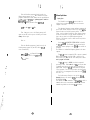
[ll]-?
[ll] -0-l 5.25” Two-Sided Double Density Diskette
1.
2.
Cylinder
40 cylinders/diskette
Track
80 ‘tracks/diskette
Sector
18 sectors/track
Byte
1 2 8 b y t e s / s e c t o r ( o n l y t r a c k 0 , s i d e 0)
256 bytes/sector (except the above)
System Track
12
File
F503H
FDC
3
F506H
CRT
System’s CRT Control
4
F509H
PRINT
System's Printer Control
KB
System’s Keyboard Control
System’s’Keyboard Status Check
H
Track 0 (side 0 & side 1) and
Track 1 (side 0)
.
80 tracks/diskette
( s i d e 0 : even-number tracks)
(side 1 : odd-number tracks)
Track
.
P
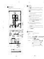
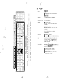
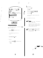
Each I/O control program is allocated to memory address
FSOO(H).
5 1 b y t e s a f t e r F500(H) i s t h e j u m p t a b l e f o r I / O
control program, it is easy to control I/O device of the
Formula-l by calling subroutine. The following shows the
structure of jump table and is stored in the Boot-Strap ROM.
Format of Diskette
F o r m a t o f t h e CP/M-80’s
I/O Prograin Specif icatiom
L
‘
System Floppy Disk Control
Expansion Floppy Disk Control
I
6
FSOFH
KBSTS
7
F512H
LPRINT
8
F51 SH
UCRT
RS-232-C (Channel-B) Data Output ’
(11)~6-2 8" Two-Sided Double Density Diskette
9
F518H
UKB
RS-232-C (ChannelkB) Data Input
Format of Diskette
10
FSlBH
USIOIN
RS-232-C (Channel-A) Data Input
.
11
F51EH
USIOOUT
RS-232-C (Channel-A) Data Output
FS21H
LPRNST’S
Centronics Standard Printer
Status Check
.
Sector
36 sectors/track (128 bytes/sector)
Disk Capacity
346.5K
bytes (except the system
track)
i
l
1.
2.
Cylinder
77 cylinders/diskette
Track
154 tracks/diskette
Sector
26 sectors/track
Byte
128 bytes/sector (only track 0, side 0)
256 bytes/sector (except the above)
I
1
F o r m a t o f t h e CP/M-80’s F i l e
System Track
Track 0 (side 0 & side 1)
Track
154 tracks/diskette
( s i d e 0 : even-number tracks)
(side 1 : odd-number tracks)
Sector
52 sectors/track (128 bytes/sector)
Disk
Capacity
988K
bytes (except the system
-46~
12
RS-232-C (Channel-B) Output
13
F524H
14
F527H
15
F52AH
USIOISTS
RS-232-C (Channel-A) Input
Status Check
F52DH
usxoosTs
RS-232-C (Channel-A) Output
Status Check
F530H
CRTINIT
16
17
track)
l Centronics Standard Printer
Control (Parallel I/O Port)
I
t
’
UCRTSTS
UKBSTS
Status Check
RS-232-C (Chaanel-B) Input
Status Check
System’s CRT Initialize
T a b l e 1 0 : Jump Table
-470
;
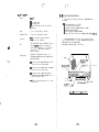
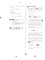
[%7-l Procedure for I/O Program Calling
H e r e i s t h e e x a m p l e , we have presented in order to show, how
to call subroutine program in order to control I/O devices.
I
1
This program has been written in assembler language,
therefore, one should know assembler language programming very
well before going into hand-on practice of this subroutine
In w h i c h w e h a v e s h o w n
Please see our below example.
program.
the procedure to read a file by direct access method.
We must specify that you can also read and write with the
h e l p o f CP/M-80’s B D O S p r o c e d u r e , a l t h o u g h i t t a k e s a l i t t l e
longer time.
System F l o p p y D i s k Control:-
:
i
The System Floppy Disk Drive Control operates by
setting controlling information in the parameter area
and calling subroutine.
I
1.
A t f i r s t , you should set total 13 bytes in the parameter
area.
F o r example:- Refer to the < Table 12 : FDC Program
Parameter >, f i e l d c o l u m n s ( 1 t o 1 3 ) m e a n s
total 13 bytes are available.
You can also look for detail information
such as parameter, length and contents.
i
i
I
:ic
:
: Memory Allocation of FDC
2.
Now, you look at the < Table 16
Program Parameter >.
3.
I n s e r t CP/M d i s k e t t e i n t o d r i v e ‘ A ’ .
4.
Type 'DIR'
5.
Look for ‘ED COM’ file
6.
type ‘ED EXAMPLE.ASM’ press <RETURN>.
(For detail, p l e a s e r e f e r t o o u r F o r m u l a - l ’ s CP/M-80
OPERATING SYSTEM MANUAL’s page 33 ‘Introduction to
Get
directory of the drive ‘A’.
; Program start
;Parameter s e t
START:
LX1
MVI
INX
MVI
INX
MVI
INX
LXX
MOV
INX
MOV
INX
LX1
MOV
INX
MOV
INX
MVI
INX
INX
INX
MU
INX
INX
MVI
H,OFFFOH
M,92H
H
M,lO
H
M'S
H
D,256
MJ
11
M,D
H
DJOOOH
MJ
H
M,D
H
MJ
II
H
H
;Parameter area address
;5.25", Drive 'B', Side '1'
;Track 1 0
;Sector 5
;Transfer b y t e s c o u n t - 2 5 6 b y t e s
’
;Transfer m e m o r y a d d r e s s - lOOOH
;Retry mode 2
;Command
CALL
OF503H
;FDC subroutine call
JMP
START
;Two sided diskette
END
thoroughly.)
7.
You will get
on it::*
8.
P r e s s ‘I’ and <RETURN> key.
Automatically, you will get list number in order to input
y o u r program.
9.
Type your program statement from your coding sheet, in order
t o s e t c o n t r o l l i n g i n f o r m a t i o n fn t h e p a r a m e t e r a r e a a n d
to call subroutine.
a new file on your CRT and following appears
F o r e x a m p l e : - We want to set parameters for Drive 'B' diskette,
t r a c k 'lo', s i d e ‘l’, s e c t o r ‘5’ a n d r e a d .
-480
.
bias - OFH (read mode)
M,OFH
H
H
M,OFFH
as Editor command file.
Now,
ED’
.
press <RETURN>.
; Example List
;
-490
,
,
*’
10.
Y o u w i l l g e t ‘9’ o n y o u r C R T .
I
11.
In order to get disconnected from ‘ED’ and re-boot to
system, you s h o u l d p r e s s ‘E’ key and <RETURN>.
1
12.
Type ‘ASM EXAMPLE’ and press <RETURN>.
( F o r d e t a i l r e f e r t o ‘CP/M-80 OPERATING SYSTEM MANUAL’.)
13.
Now, i f y o u g o b a c k t o t h e d i r e c t o r y , y o u w i l l g e t y o u r f i l e
such as:(1) EXAMPLE
(4) EXAMPLE
.*
. ;’
..r
*: .
;
[~IJ -7-2 IPL (Initial Program Load)
At the end, when you finish input of your program statement,
y o u s h o u l d p r e s s <CTRL> ‘2’ k e y .
BAK (2) EXAMPLE
HEX
etc.
1
ASM (3) EXAMPLE
PRN
14.
You need to ‘LOAD’ command.
(Due previously we made ‘HEX’ file only now you have to make
‘COM FILE’ in order to run your program on CP/M-80 Operating
System.)
15.
Type
16.
In the directory ‘EXAMPLE
17.
I f y o u t y p e ‘EXAMPLE’ and press <RETURN>,
your program will start running automatically.
:
‘LOAD EXAMPLE’ press <RETURN>.
COM’ will appear.
‘End’
l.
- .
This program is used only at the system starting to
i n i t i a l i z e t h e s y s t e m I / O c o n t r o l l e r , loads the system program
When you call
from the floppy diskette to the main memory.
this program, t h e F o r m u l a - l b e c o m e s a t a i n i t i a l s t a t e t h r o u g h
Usually, there is no need to use this program.
Software-Reset.
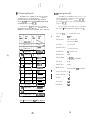
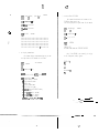
[II]+3 FDC (Floppy Disk Control)
Input Parameter
I
i
I
I
I
1
I
: 13 bytes of parameter informations are set in
FENT (FDC parameter setting area).
Output Parameter : T h e s t a t u s i s s e t i n A - r e g i s t e r .
Register
: All registers are reserved except A-register.
Calling Method
: CALL FDC <F503(H)>
T h i s p r o g r a m i s t h e b a s i c i n s t r u c t i o n t o o p e r a t e 5.25”,
This is operating by setting controlling
8” floppy disk drives.
informations in the parameter area and calling subroutine.
Command Name
-----pG
I
Basic Command
I
1
Function
SEEKZ (Seek to zero track) 1
OFH
EREAD (Seek & read data)
12H
EWRITE (Seek & write data)
-
r
Expansion
Command
/
7
OOH )
T a b l e E l : FDC Command
.
-so-
Note
Physical unit number
1
:
D o u b l e d e n s i t y d i s k e t t e , “ T r a c k 0” i n “ S i d e 0” i s
operating in the same method as of single density
If you select more than one disk drive
diskette.
at the same time, i t b e c o m e s a u n i t e r r o r .
Note 2 :
When using single density diskette the transfer data
length is multiple of 128 bytes, that is to say
1 2 8 b y t e s x 1 , 128 bytes x 2 or 128 bytes x 3 and so
And for double density diskette the multiple of
on.
For single density if you set 129, 130 or
256 bytes.
some other number in between 129 bytes to 255 bytes,
then it is automatically being set to 256 bytes.
When the transfer data length exceeds the capacity of
the last sector of the track, the track number is
r e n e w e d e x c e p t f o r t h e “ T r a c k O”, “ S i d e 0” o r t h e
last track.
Note 3 :
When you intend to retry executing expansion command,
usually always 02H value being designated.
Note 4 :
When values of the bias except 3 kinds shown in
< T a b l e 1 1 : FDC Command > are set, it b e c o m e s bias
error.
Selecting Disk Drive
0 =I=> 5.25” Disk Drive
1 -> 8” Disk Drive
Parameter Information
Classification
Classification Command
Name
: 3 retry (non seek zero)
I
I
I
Basic
Command
Expansion
Command
Command
UN TK SC BY
1 SEEK2
4,
U1
o ( x / x j x j x 1 x ) x j x j o 1 x / x
EREAD
1 EWRITE
AD RY
(0: set)
(x: no set)
0
o
0
o
0
o
0
o
0
o
0
o
x
x
x
x
Table 13 : Parameters Setting
Table 12 : FDC Program Parameter
-520
-539
0
x
0
:.
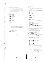
This program being executed as a result of setting
following status in the accumulator (A-register) and then
return to the main program.
T h e r e a r e f o l l o w i n g E r r o r S t a t u s Cod,? b e s i d e s t h e o n e o f
previous page.
I
Contents of Error
1
I EOH
I
Bias Data Error
1
I E 1 Ii
I
Unit Data Error
I
I
DMA Controller Error
I
I
I-- Bit-~~Position I
Contents of Status
F[;z/
ty/
I
I
See following status code list
E2 ti
s3 J
T a b l e 15 : E r r o r S t a t u s C o d e L i s t 2
D4
Error at the executing EREAD command
DS
Error at the executing EWRITE command
D7
I
Error Code
’
I
Zero (Unused)
I
I
Zero (Unused)
I
. .
.
FFFO t 0
Unit Number
I
FFFO t 1
1
FFFO t 2
Contents of Error
I olololo I
0
0
0
1
I
0
0
1
0
. ... -*. - 4,
.
I
Normal ending of command
FFFO t 8
RECORD NOT FOUND
I
WRITE FAULT
I
WRITE PROTECT
1
1
0
DRIVE NOT READY
Number of Transfer Bytes (High)
ba
.
* There are 9 types of errors as listed in the above table.
Transfer Address (High)
I
Unused
1
FFFO t A
Bias for Each Command
I
Unused
Selecting One or Two Sided Diskette
I
Table 16 : Memory Allocation of FDC Program Parameter
T a b l e 1 4 : Error Status Code List 1
-54-
7
Retry Mode <02(H)>
Unused
FFFO t C
I
Transfer Address (Low)
FFFO t 9
FFFO t B
I
I
FFFO t 7
I
1
Sector Number
Number of Transfer Bytes (low) 7
FFFO t 6
CRC ERROR
0
FFFO t 4
-
I
FFFO t 5
SEEK ERROR
0
1
FFFO t 3
I
Normal ending o f command. In case o f
reading data field with deleted data
address mark.
1,l
I
Track Number
-55-
I
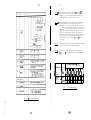
[ll]-7-4 CRT (System’s CR? Control)
Input Parameter
I
:*
t.
r :
a
a
4
.
.
- .
.
-
.
I
: CALL CRT <F506(H)>
This is the program to make s a m e f u n c t i o n a s t h e e x t e n d
By setting a character code to display into A-register and
CRT.
calling this program, you can display character on the CRT.
In case of using this program, display speed of serial
Direct access is
transferring rate is about 19200 BPS.
necessary t o V-RAM, i n c a s e y o u r e q u i r e f a s t d i s p l a y s p e e d .
See < Table 23 : Video-RAM I/O Map > about the V-RAM address.
Moreover, i n c a s e o f d i r e c t a c c e s s t o V - R A M , i t i s n e c e s s a r y
to initialize the address pointer of V-RAM.
I n t h i s c a s e , c a l l ‘ C R T I N I T <F530(H)>‘. So, V-RAM address pointer
i s i n i t i a l i z e d , and the screen is cleared.
Below we provide detail information pertaining to system’s
CRT control codes.
2nd Byte
B (42H)
1
c
I
I
D (44H)
I
I
(43~)
i
I
E (45H)
I
F (46H)
I
(08H)
.- . .
HT
(09H)
: Move the cursor one character to the left side.
This control code is invalid if the cursor is on
the first position (extreme left) of top of the
line.
: Move the cursor to the TAB position of every 8
characters.
G (47H)
H (48H)
I
I
(OAH)
: Operate the line feed.
FF
(OCH)
: Clear all the screen and move the cursor to first
column of the first line.
CR
(ODH) : M o v e t h e c u r s o r t o the.top o f t h e l i n e .
SO (OEH) : Set the “Shift-Out” mode.
(Note 1)
SI (OFH) : Set the “Shift-In” mode.
(Note 2)
DC3 (13H) : S e t t h e m o d e s e m i - g r a p h i c c h a r a c t e r s .
DC4 (14H) : C a n c e l t h e m o d e s e m i - g r a p h i. c c h a r a c t e r s .
(Initial State)
E S C (1BH) : S e t ‘IESC” s e q u e n c e m o d e , for d e t a i l r e f e r t o
‘ESC’ Sequence Functions & Code List see
(Note 3)
next page.
DEL (7FH) : Invalid
-560
I
I
I
Moves the cursor left one character.
I
Clear all the screen.
~~~- ~~
I
Ignore the characters over 80 columns/line.
Erase line (After Cursor).
M (4DH)
When cursor at the last line, if this
program accept LF code at this time, cursor
automatically goes to the first line.
Clear screen, and screen does not scroll up
even if after accepting LF code.
N (4EH)
I
0 (4FH)
U
I
Screen scroll up by LF code. (Initial State)
Screen scroll up.
Screen scroll down.
I
Cursor does not move.
I
Cursor does not m o v e .
I
Cursor being not displayed,
Cursor being displayed. (Initial State)
(SSH)
Y (59H)
I
Move the cursor to first column of the first
line.
K (4BH)
I
S (53H)
I
I
Moves the cursor right one character.
Erase screen (After Cursor).
1 p uw (
I
Moves the cursor down one line.
J (4AH)
R (52H)
LF
---I d
Display those characters in the next line,
which exceeds 80 columns/line.
(Initial State)
BEL (07H) : Beep the alarm.
BS
Functions
Ii
Moves the cursor up one line.
: All registers are reserved.
Calling Method
:*
* Y.a
.
I
‘Ii
!
Output Parameter : Not exist
Register
,. .
: Set the character code to display into
A-register (ASCII code).
Display test.
I n d i c a t e d “H” a l l t h e s c r e e n .
’ Cursor addressing.
(Note 4)
I (SW
Print out the contents of the screen. (Note 5)
A (SEH)
Print out the contents of the full line
where the cursor being placed.
( N o t e 5)
T a b l e 1 7 : ESC Sequence Disposition List
,
I
Note
’
1
:
.
.
Shift-Out mode, f o r d e t a i l y o u s h o u l d r e f e r t o
< Table 22 : C R T & P r i n t e r C h a r a c t e r C o d e T a b l e ( 2 ) >,
where you can add up various different characters for
your specific uses.
For example :-
;
*. .
;. .’ .
1’
. ’
. -
Greek characters, Japanese characters
etc.
Note 2 :
Shift-In mode consist of English characters and
symbols at initial state.
Note 3 :
In t h i s c a s e , d e s i g n a t e c u r s o r a d d r e s s a c c o r d i n g t o
In the first byte, line number
the code of two bytes.
being designated and in the second byte, column number.
The next page shows the cursor addressing code.
9
I
i
t
c
:.
: 0:
:
;
.
d .
Note 4 :
Note 5 :
I n c a s e o f t h e ‘MC’ s e q u e n c e , i f d e s i g n a t e d b y t e
numbers are not minimum 2 bytes, which is unacceptable
to program, a n d t h e r e f o r e t h e r e g u l a r d i s p l a y m o d e
does not return to main program.
Print out contents only from the system’s (thermal)
winter.
I
f-
I1
1
J
.-.
.. *,-
I
SPACE
2
I
I
21
22
5
35
3
w
22
23
6
36
7
&
26
27
:
3A
0
t
27
28
:
3B
9
(
28
29
<
3c
I
I
L
’
1
20
2A
II
I
21
31
I
I
4
>
I
12
t
2B
32
?
3F
13.
#
2c
33
@
40
2D
34
A
l
2E
35
‘B
42
/
2F
36
C
43
17
0
30
37
D
44
18
1
31
38
E
45
19
2
32
39
F
46
20
3
33
40
G
47
14
15
16
1
I
-59-
I
1,
I
1
T a b l e 1 8 : C u r s o r AddressIng C o d e ( 1 )
-58-
34
41
.
p1]-7-5 PRINT (System’s Printer Control)
Input Parameter
: Set the character code to print into
A-register (ASCII code).
Output Parameter : Not exist
Register
: All registers are reserved.
Calling Method
: CALL PRINT <F509(H)>
Printer is controlled by the software.
The user can control the printer as well as printing, only
when the user sets the printer code in the accumulator
(A-register) and calls this program.
At t h e t i m e o f c a l l i n g
t h i s p r o g r a m a l l r e g i s t e r s g e t r e s e r v e d : - means at the
t i m e o f p r o g r a m c a l l i n g , t h e i n n e r cont+:i;rt o f a l l r e g i s t e r s
already being reserved and therefore not destroyed.
The program operates buffering of 80 characters, when the
characters are over 80 or the device receives the CR <OD(H)>
code, the printer starts printing because the printer can not
print each and every character.
Below we provide detail information pertaining to system’s
(thermal) printer control codes.
v
B S ( 0 8 H ) : C a n c e l t h e l a s t c h a r a c t e r .before “BS” c o d e .
This code is invalid if the position is the
top of the line without any character before
it.
H T
(09H) : M o v e t h e p r i n t e r ’ s h e a d t o t h e T A B p o s i t i o n o f
every 8 characters.
LF (OAH) : Invalid
FF (OCH) : M o v e t h e p r i n t e r ’ s h e a d t o t h e t o p o f t h e n e x t
page
l
CR (ODH)
Table 18 : C u r s o r A d d r e s s i n g C o d e ( 2 )
: Print one line of buffer content, and carriage
return with line feed,
SO (OEH) : S e t t h e S h i f t - O u t m o d e .
(Note 1)
SI (OFH) : Set the Shift-In mode.
(Note 2)
DC3 (13H) : S e t t h e m o d e semi-graphk c h a r a c t e r s .
DC4 (14H) : C a n c e l t h e m o d e s e m i - g r a p h i c c h a r a c t e r s .
(Initial State)
E S C (1BH) : Operate undermentioned operations :<ESC> t ‘ F ’ ( 4 6 H ) : I g n o r e t h e c h a r a c t e r s o v e r 8 0
columns/line.
<ESC> t ‘G’ (47H) : Print those characters in the next
l i n e , which exceeds 80 columns/line.
0.
(Initial State)
<ESC> t ‘V’ (56H) : Print the characters at a interval of
one line.
<ESC> + ‘ W ’ ( 5 7 H ) : P r i n t t h e c h a r a c t e r s w i t h o u t i n t e r v a l .
(Initial State)
DEL (7FH) : Invalid
Note 1 :
Shift-Out mode for detail you should refer to
< Table 22 : C R T & P r i n t e r C h a r a c t e r C o d e T a b l e ( 2 ) >,
where you can add up various d i f f e r e n t c h a r a c t e r s f o r
your specific uses.
For example :-
Note 2 :
Greek characters, Japanese characters
etc.
[l!)-7-6 KB (System’s Keyboard Control)
Input Parameter
: Not exist
Output Parameter : T h e p r e s s e d k e y ’ s c o d e b e i n g s e t i n A - r e g i s t e r .
Register
: All registers are reserved except A-register
& Flag-register.
Calling Method
: CALL KB <FSOC(H)>
By calling this program, a f t e r k e e p i n g k e y c o d e ’ s i n t o
Accumulator (A-register) and returns back to main program.
All registers except A-register being reserved.
At the time of calling ‘BDOS
Function-Keys, Cursor Control-Keys
For, Function-Keys maximum 8 bytes,
including Numeric-Keys maximum 2
‘BIOS’.
Function’, the key codes of
and Numeric-Keys get changed.
and for Cursor Control-Keys
bytes get changed inside the
When you call this program directly the original key codes
< Table 19 : Keyboard Code > of Function-Keys, Cursor Control
-Keys and Numeric-Keys do not change inside the ‘BIOS’ and
proceed inside the Accumulator (A-register) and returns back to
main program.
Shift-In mode consist of English characters and
Symbols at initial state.
[tll -7-7 KBSTS (System’s Keyboard Status Check)
Input Parameter
: Not exist
O u t p u t P a r a m e t e r : W i t h o u t d a t a => A - r e g i s t e r - 00(H) (Z=Flag=l)
With data
=> A - r e g i s t e r - FF( H) (Z=Flag=0)
-62-
Register
: All registers are reserved except A-register
& Flag-register.
Calling Method
: CALL KBSTS <FSOF(H)>
-630
QQ
56
I
EE
.~
S
3
I
57
77
-.
DD
4
$
FF
5
%
G
6
i
F4
H
UU
B , N
YY
7
’
FS
JJ
8
(
F6
M
1I
00
I
0
F8
P
T
1
<
t
>
.
KK,L,
L
9
1
F7
+
;
-
=
?
,/
C
@
{
I
\
?+
BACK
SPACI
LINE
IFEED
DEL ESC
REPT SHIFT
(
SHIFT
LOCK
A
-
F9 HOME -+ +-
Fig.18 : Keyboard Layout (1)
- V ,
TT
F3
There is no output of key code if you hit this Key.
,C
I
RR
F2
4
1
0
FEED
(“2)
6
9
78
* 2.
58
18
81
83
84
I
59
85 , 86
: Keyboard
Layout (2)
s -.--
82
Note : Keys with mode numbers as per
Fig.
80
88
I60 I 61
87
(Table 19 : Keyboard Code - Capstan Lock Off/On)
79
89
69
72
68
71
73
70
67
66
l
65
91
64
90
--I-62 63
The 'FEED' - key forward the roll paper of the printer.
* 1. The system is reset by means of hitting this key with 'CTRL'- key.
I
(* 1, 2)
c
76
H TAB
-
Fl
, Z _ 7X,
CAP
LOCK
WW
2
2
a
A
SHIFT
3TRL
1
!
RESET
c
(“1)
. -_ -*.--._ ._..
Unshift 1
Shift
1
1 Shift & Control 1
Control.
/ *.
,” 4
.
,
.* . .
i.
; \J
t
f
I
t.
Y
1
.
i
;
.
‘.
-.
.
!
$
5
5
35
x
25
6
6
36
&
7
7
37
?
.
.
84
85
85
26
86
86
27
87
87
[
r
iI
I 88 I
88
1
‘29
89
89
10
~0
30
0
30
80
80
Ill
I-
I2D
12
A
SE
l3
*\
SC
IBACK f
SPACE
08
L
115
b
N
(3D
1
I
1
BACK 1
SPACE
I
/
1E
1E
7c
1C
1c
BACK 1
SPACE
BACK
SPACE
08 1
j
129
I
1
I
r
8D
7E
08 1
I26
140
[
/
f
p
NULL
( 60
SB
/
{
/
7B
1
1
CTRL
1
j
I
08
CTRL
cm
s
73
S
53
DC3
13
DC3
13
( 64
D
EOT
F
46
ACK
06
ACK
06
34
g
67
G
47
BEL
07
BEL
07
35
1
,36
j
37
k
h
1
6A
]
’
J
4A
LF
OA
K
4B
VT
OB
6B
1
1
j
#
6C
j
1
L
ETB
17
I40
1
:
17
e
E
45
ENQ
05
ENQ
05
I 41 I 1 I 5D I 1 I 7D I
R
52
DC2
12
DC2
12
T
54
DC4
14
DC4
14
122
1,
24
1
i
23
1
P
75
1
o
69
1
U
f
6F
70
1
1
I
1
P
)
0
1
55
1
NAK
49
f
HT
1
09
SI
1
OF
4F
1
50
DLE
1
15
10
1
1
1
r
44
1
2
45
1
x
1
1
HT
I
09
I
I
146 ! =
1
I47
DLE
10
1
48
1
2A
1
1
1
7A
j
Z
78
1
X
1
76
1
62
)
1
1
V
1
5A
1
B
1
BS
’
OC
/
88
1
08
LF
OA
VT
OB
-FF
[-CC
1
SHIFT
SHIFT
(
1
1
1
CAN
ETX
SYN
1
STX
1A
1
18
1
/
16
1
02
SUB
1
03
i
I
i
-670
1
1
1 8B
RETURN OD
1
42
1
SUB
58
56
FF
1
RETURN OD
1
43
08
1
SHIFT
1
b
]
RETURN OD
163 ! c
v
1
1
2B
1
CAN
1
1
1
ETX
/
SYN
1
STX
]
1
1
T a b l e 1 9 : Kevboard Code - C a p s t a n L o c k O f f ( 2 )
T a b l e 1 9 : Keyboard Code - C a p s t a n L o c k O f f ( 1 )
-660
1
15
OF
*
43 SHIFT
1
]
1
REl’URN OD
NAK
SI
3A
(
)
17
(
+
4C
ETB
u
1
1
1
57
/
3B
48
W
42
1
H
BS
68
77
1
EOT [ 04
66
w
I21
(
04
f
16
( Y 1 79 1 ‘d 1 59 1 EM I l9 I EM I l9 I
1
33
I38
I,
1
31
t
74
1
1
01
1
t
1
SOH
139
19
CTRL
1B
01
11
1
j
j
SOH
DC1
72
ESC
41
11
r
j
A
DC1
18
1B
NULL j 00 1
61
51
1
/
00 f
a
Q
65
ESC
1
71
L
)
30.
1
1
1
Q
120
v
1
I @
.
84
39
114
.
24 ’
1
9
r
L
.
34
9
II
.
,
4
I 8 I 8 I I 38 I I ( I 28 II
. .
.(
*&
,
’
*
.
4
I 25
.
1A
1
18
1
03
1
16
1
02
1
I
,
’
82
F6
96
83
F7
97
84
F8
85
F9
96
96
97
97
98
98
98
99
99
99
HOME 9A
9A
9A
9A
9B
9B
9c
9c
9D
9D
;
96
i
97
98
.
99
1
.. .
86
CA
CA
87
-
9B
9B
BD
CD
CD
88
-
9C
9c
AB
BB
CB
C B
89
t
9D
9D
J
9E
ESC
1B
+
AA
BA
63
1 -
AD
64
;
. -. - e.’
1B
61
r
62
CL
ESC
lB
ESC
1B
i
ESC
65
1 7
A7
B7
C7
C7
90
66
8
A8
88
C8
C8
91
67
9
A9
B9
68
4
A4
69
i 5
70
6
A6
71
1
Al
72
2
A2
I
A5
c9
84
I
I
I
/
B5
I
9E
FEED
9E
FEED
1
c5
I
c4
‘
!
1
9E
FEED ’
T a b l e 1 9 : Keyboard Code - C a p s t a n L o c k O f f ( 4 )
c5
B6
C6
C 6
Bl
Cl
C
B2
c2
’
l
c2
Table 19 : Keyboard C o d e - Capstan Lock O f f ( 3 )
-680
.
c9
c4
,
I
FEED
:
-69-
\
Y’
f\
1 Mode 1
U n s h i f t ,I
29
CTRL
30
A
37
41
CTRL
a
SOH
1 61
H ;
40 39 :
6 B
11
38 3A
CTRL
01
16CI
*+
SOH
01
VT
OB
VT
08
FF
IOC
FF
IOC
2B 2A
I
J
I
I
E
14C
1 Shift & Control 1
Control
I
CTRL I
k
K
138IL
- l .
l
.
I
IF
$.
Shift
’
(
88 8A
88 8A
1 41 1 1 1 5D I 1 I 7D I
,18
1
19
.
20
r
21
122
c
\
R
52
r
)72
DC2
12
T
54
t
74
DC4
Y
39
Y
79
u
55
U
:I
49
i
23
24
L
0
4F
P
50
L
P
.DC2
12
142
14
DC4
14
1 43 (SHIFT 1
EM
19
EM
19
1
75
NAK
15
NAK
13
69
HT
09
HT
6F
0
A
70
I
I
109
.
)
2
OD
1
RETURN1
OD,
1
SA
45
x
38
46
C
43
OF
SI
OF
,47
v
56
DLE
10
DLE
10
i 48
1 B
1 42
1
’
1
z
1
1
RETURN1
OD
1 SHIFT 1
1 SHIFT 1
SI
T a b l e 1 9 : Keyboard Code - Capstan Lock On (1)
-7Q-
8
44
IREURN
7A
)
: 78
CAN
C
63
ETX
V
76
b
j 62
SYN
1
STX
RETUPNj
1
/
1
1A
OD
1
SUB
1
CAN
18
03
ETX
03
16
SYN
16
STX
1 02
f
T a b l e 1 9 : Keyboard Code - Capsta,&ock On (2)
-71-
1A
18
02
1
SHIFT 1
I
SUB
x
1
1
1
1
I Mode I
Unshift
Shift
1
14D
1
2c
. ..- .
r
.\ f
m
16D
.
2E
>
3E
53
/
2F
?
3F
54
REFT
35
SHIFT
56
H TAB
.
IvPCR
3c
<
52
:
IOD
8E
1
CR
SHIFT
09
H TAB
[OD
a
I
c
8E
I
I8F
8F
REPT
r
I SHIFT
M TAB
1 Shift & Control 1
8C
I
REE’T
09
Control
I
q
’
REPT
i
SHIFT
y
09
1
H TAB 1
09
?.
.
:;
. ;* .
1
.
l
:’
160
DEL
,’
-. . .
1
61
*
62
DEL
7F
ESC
1B
+
AA
I
.
DEL
_
ESC
7F
18
-
I
1B
ESC
r
-c
CA
CA
\ CD
CD
AB
BB
CB
CB
A8
Ba
ca
c8
67
9
A9
B9
c9
c9
68
4
A4
B4
c4
c4
P9
I 5
I
A5
i
t
B5
I
I c5
T
70
v
71
m 72
I
,
6
A6
B6
1
Al
81
82
2
,
A2
,
I
a5
F9
99
I
98
r
99
i
I
98
p-d
/.:
v-
98
’
I1
~--
D
,8
i
98
18
66
1
F8
I
BD
AD
. CL
ESC
k
7
64
7F
7F
BA
L
63
1
DEL
84
I
I
I
-4
c5
Table
19 : Keyboard
Code - Capstan Lock O n ( 4 )
k
~~
’ C6
C6
’
C1
Cl
I
c2
,
c2
.
;
La
T a b l e 1 9 : Keyboard Code - Capstan Lock On (3)
-72-
-730
99
[ill-7-10 UKB (N-232-C Channel-B Data Input)
[ll] -7-8 LPRINT ‘(Centronics Standard Printer Control)
Input Parameter
: Set the character code to
A-register (ASCII code).
Input Parameter
print into
Output Parameter : Set a input data from Channel-B into
A-register.
Output Parameter : Not exist
Register
: All, registers are reserved.
Calling Method
: CALL LPRINT <F512(H)>
This is a program to control a external printer with
Centronics Standard Printer’s Interface connected to Parallel
I/O Ports.
For detail refer to the specifications of the connected
printer pertaining to it’s Function codes.
1
Calling Method
: CALL UCRT <FSlS(H)>
: CALL UKB <F518(H)>
A-register
IllI -7-11 USIOIN (RS-232-C Channel-A Data Input)
: Not exist
Output Parameter : Set a input data from Channel-A
A-register.
Output Parameter : Not exist
. _a .
Calling Method
Input Parameter
: Set a data into A-register which you intend
to output from Channel-B.
: All registers are reserved.
: All registers are reserved expect
& Flag-register.
The RS-232-C (Channel-B) being assigned to < TTY > input device
when running on CP/M-80.
[111-7-9 UCRT (RS-232-C Channel-B Oata Output)
Register
Register
This is a’ program to input the data from the RS-232-C
(Channel-B) Port. The other conditions are the same as those
o f i t e m < [ll]-7-9 U C R T >.
Be careful not to call this program without a external
printer, otherwise this program cannot return to the CP/M-80.
Input Parameter
: Not exist
into
Register
: All registers are reserved except A-register
& Flag-register.
Calling Method
: CALL USIOIN <FSlB(H)>
4.: ’
..
~
-_
L
.
.
This is a program to input the data from the RS-232-C
(Channel-A) Port.
The other conditions are the same as thoE=%e of ‘Channel-B’ Port.
This is a program to output the data from the RS-232-C
The Baud-Rate value being set by the DIP(Channel-B) Port.
Switch, which is at the rear side of the Formula-l.
The detail information pertaining to Serial I/O mode and bit
f o r m a t a r e a s f o l l o w s :Mode
Character Bit
(Ill-742 USIOOUT (RS-232-C Channel-A Data Output)
: Asynchronous (Start Stop Synchronous)
Length
Input Parameter
: 8 bits/character
: Set a data into A-register which you intend
to output from Channel-B.
Parity
: Even parity
Output Parameter : Not exist
Stop Bit Length
: 2 stop bit
Register
: All registers are reserved.
Calling Method
: CALL USIOOUT <FSlE(H)>
In this program control signals such as CS, CD, RS, ER,
e t c . are not used.
The RS-232-C (Channel-B) being assigned to < TTY > output device
when running on CP/M-80.
This is a program to output the data from the RS-232-C
(Channel-A) Port.
The other conditions are the same as those of ‘Channel-B’ Port.
-75-
-74i
,
0
4
[ll]-7-13 LPRNSTS (Centronics Standard I / F Printer Status Check)
I
‘. s
’ ‘.. .
Input Parameter
[II] -7-16 USIOISTS (RS-232-C Channel-A input Status Check)
: Not exist
Input Parameter
O u t p u t P a r a m e t e r : B u s y -> A - r e g i s t e r - 00(H) ( Z - F l a g = 0,)
R e a d y -> A - r e g i s t e r = FF(M) ( Z - F l a g = 1 )
: Not exist
O u t p u t P a r a m e t e r : W i t h o u t d a t a => A - r e g i s t e r = 00(H) ( Z - F l a g - 1 )
-> A - r e g i s t e r - F F ( H ) ( Z - F l a g - 0 )
With Data
Register
: All registers are reserved except A-register
& Flag-register.
Register
: All r e g i s t e r s a r e r e s e r v e d e x c e p t A - r e g i s t e r
& Flag-register.
Calling M e t h o d
: CALL LPRNSTS <F521(H)>
Calling Method
: CALL USIOISTS <F52A(H)>
This is the status c h e c k program of the Centronics Standard
Interface Printer.
This is a status check program of the input data from
the RS-232-C (Channel-A) port.
This program only checks ‘Receiver Buffer Ready‘ status.
M-7-14 UCRTSTS (RS-232-C Channel-B Output Status Check)
Input Parameter
[11]-747 USIOOSTS (RS-232-C Channel-A Output Status Check)
: Not exist
Input Parameter
Output Parameter : B u s y => A - r e g i s t e r - 00(H) ( Z - F l a g - 1 )
Ready-> A-register = FF(H) (Z-Flag - 0)
Register
Calling Method
. - l.
Jq-
.
.J
..
c
: All registers are reserved except A-register
& Flag-register.
O u t p u t P a r a m e t e r : W i t h o u t d a t a => A - r e g i s t e r - 00(H) ( Z - F l a g = 1 )
-> A - r e g i s t e r - F F ( H ) ( Z - F l a g - 0 )
With Data
Register
: All registers are reserved except A-register
& Flag-register.
Calling M e t h o d
: CALL USIOOSTS <F52D(H)>
: CALL UCRTSTS <F524(H)>
This is a status check program of the output data from
the RS-232-C (Channel-B) port.
This program only checks ‘Transfer Buffer Empty’ status.
: Not exist
This is a status check program of the output data from
the RS-232-C (Channel-A) port.
This program only checks ‘Transfer Buffer Empty’ status.
.
[11)-7-E UKBSTS (RS-232-C Channel-B fnput Status Check)
Input Parameter
: Not exist
[ll] -7-18 CRTINIT (System’s CRT Initialize)
O u t p u t P a r a m e t e r : W i t h o u t d a t a => A - r e g i s t e r = 00(H) (2 -Fla 8
With data
-> A - r e g i s t e r - F F ( H ) (2l-F18 8
= 1)
= 0)
Register
: All registers are reserved except A-register
& Flag-register.
Calling Method
: CALL UKBSTS <F527(H)>
This i s a s t a t u s c h e c k p r o g r a m o f the input d a t a from the
This program only checks ‘Receiver
RS-232-C (Channel-B) port.
Buffer Ready’ status.
The RS-232-C (Channel-B) Input Status being assigned to < TTY >
Input Status when running on CP/M-80.
-769
Input Parameter
: Not exist
Output Parameter : Not exist
Register
: A l l r e g i s t e r s a r e reserved.
Calling Method
: CALL CRTINIT <F530( H)>
This is a program to initialize system’s CRT.
By calling t h i s program V - R A M a d d r e s s pointer g e t i n i t i a l i z e d
a n d m o v e s t o f i r s t a d d r e s s p o s i t i o n o f t h e V - R A M , a n d thereafter
screen get cleared.
-77-
..
6“
‘4 :y
Q’ J‘b
After you input the name of the disk drive in use,
following message will appear on your CRT.
fill-8 System Utility Program’s
This utility program consists of ‘FORMAT’, ‘FSYSGEN’,
‘SYSTEM’, ‘PROMW’ and ‘FUNC’ commands has been made by our
company and supplied t o our users as transient command.
)
The object of this command is to create a new index
on the new or old diskette in order to proceed for using
with our computer.
U s u a l l y , new diskette can not be read and
w r i t e o n i t , without formatting.
:
; 4
,_
’
.
impossible to
Time to time, if diskette being damaged due to unusual
handling, strong electric and magnetic forces then we need
to do the formatting.
You should be very careful when executing this program,
because the contents of the diskette will get erased as this
process is over. The operations are as follows.
<RETURN>
A>FORMAT
+** Diskette formatting (Vers.
Drive name 3
A . A l l t r a c k s 00-** T r a c k :
When you intend to format all the tracks of the diskette,
type ‘A’ key and press <RETURN>.
[11)-&l FORMAT : Command for diskette format
1
Formatting track address ?
*.*)
A,B,C,D,E,F,G,H
***
(or RETURN
to reboot):
In this state, set the diskette to record a format into
the floppy disk drive and input the same disk drive’s name and
press <RETURN> key.
The name of the disk drives as stated above are the same as of
Further, i f y o u i n t e n d t o f o r m a t o n e t r a c k o n l y , t h e n y o u
should type the specific track number to be formatted and press
<RETURN> key, following message will appear on your CRT.
Formatting start ? (Y/N)
I n o r d e r t o s t a r t f o r m a t t i n g , p r e s s ‘Y’ k e y .
If the process of formatting ends without any error the process
complete message will appear on your CRT, and gets back to
initial state.
If you do not wish to start or intend to return to initial
state press ‘N’ key only.
Further, d u r i n g t h e p r o c e s s o f f o r m a t t i n g i f t h e r e b e i n g
a n e r r o r , the following error message will appear on your CRT,
and gets back. to initial state.
Formatting start
Read check start
Process complete - - - - - - - - - - - - - - - Normal end
(Disk write error II!) - - - - - - - - - - A b n o r m a l e n d ( I )
( D i s k r e a d e r r o r !!!)
--------- Abnormal end (II)
CP/M-80, and details are as follows.
Drive
A
: 5.25’ two-sided double density
Drive B : 5 . 2 5 ’ t w o - s i d e d d o u b l e d e n s i t y
Drive C : 5 . 2 5 ” t w o - s i d e d d o u b l e d e n s i t y
Drive D : 5.25’ two-sided double density
Drive E : 8” one-sided single density
Abnormal end (I)
: The diskette is not inserted properly,
unlocked or in a state of write-protect.
Abnormal end (II) : When after recording the format, the
data in the diskette are impossible to
be read correctly.
We have shown the procedure of formatting a new diskette
on the following page.
Drive F : 8 ” o n e - s i d e d s i n g l e d e n s i t y
Drive G : 8 ” t w o - s i d e d d o u b l e d e n s i t y
Drive H : 8” two-sided double density ’
-789
-79-
7.
Formatting start 1 (Y/N)
*** 6QK CP/M
Vers. 2.2 Formula-l System ***
BIOS Created By YCU Co., Ltd. (1983.**.**)
A>FQRMAT
.
Press
**u D i s k e t t e f o r m a t t i n g ( V e r s . *.*) **”
Drive name ? A,B,C,D,E,F,C,H (or RETURN to reboot):
Process complete !
---------------------------------------------------------
This is the end of formatting of a new diskette.
(In order to continue formatting more diskettes, please
refer to Note 2)
Process complete I
8.
Fig. 19 : FORMAT
For finishing this process.
Press <RETURN> in order to reboot.
Messaae
Note
1
:
PROCEDURE OF 'FORMAT' A NEW DISKETTE:A
'Y' for Yes.
Formatting start
Read check start
1:
_’
After displaying
new diskette, we mean a ‘new blank diskette’.
1.
Formula-l power switch ON.
2.
Insert the
CP/M-80 SYSTEM DISKETTE
1) When using Disk Drive A, B, C and D 5.25"
diskettes the track numbers will be from 00 to
3 9 d u e 40 t r a c k s a v a i l a b l e f o r f o r m a t t i n g . I f
you intend to format track 5 only then input 5
and press <RETURN>. If yo!.. intend to format
5 , 6 a n d 7 t r a c k s , then you have to input and
‘FORMAT’ each track number one-by-one separately.
This means that you can format only one track
at a time except for A. All tracks.
2) When using Disk Drive E, F, Geand H 8" diskettes,
the track numbers will be from 00 to 76 due 77
tracks available for formatting.
into Drive ‘A’
and lock.
Rest is same as above.
3.
Insert a new diskette (to be
and lock.
formatted) into Drive 'B'
Note 2 :
If you intend to continue ‘Formatting’ more
unlock Drive ‘ B ’ a n d i n s e r t a g a i n a
n e w d i s k e t t e a n d l o c k , follow our instruction from
diskettes, just
4.
After displaying prompt - ‘A>‘.
5.
Type ‘FORMAT’ press <RETURN>.
3 .m
Now, you will find computer asking for
Drive name ? A,B,C,D,E,F,G,H, (or RETURN to reboot):
Type ‘B’ and press <RETURN>.
6.
,
Displaying
Formatting track address 3
A.
All tracks W-39 track:
Type ‘A’ and press ‘<RETURN>.
(For detail refer to Note 1)
.
i
[II]-&2 FSYSGEN : Command for system generation
6.
You will get following message on your CRT.
SOURCE ON A THEN TYPE RETURN
This command is same as 'SYSGEN' of transient command of
the CP/M-80, modified to Formula-l. See CP/M-80 manual for
method of operation.
7.
The object 'FSYSGEN' is to copy 'CCP', 'BDOS', 'BIOS'
which are inside the system tracks of source drive diskette
to the destination drive diskette.
Press <RETURN>.
You will get following message on your CRT.
FUNCTION COMPLETE
This means process of reading from source diskette being
completed.
+++ 6OK CP/M Vers. 2.2 Formula-l System ***
BIOS Created By YCU Co., Ltd. (1983.**.**)
A>FSYSGEN
8.
You will get following message on your CRT.
SYSCEN VERSION *.*
DESTINATION DRIVE NAME (OR RETURN TO REBOOT)
SOURCE DRIVE NAME (OR RETURN TO SKIP)
9.
10.
Type destination drive name as 'B' and press <RETURN>.
(You can use any one of the following drives name
'A', 'B', 'C', 'D')
Following message will appear on your CRT.
FIR. 20 : FSYSGEN Message
DESTINATION ON B THEN TYPE RETURN
PROCEDURE OF 'FSYSGEN' A NEW DISKETTEr11.
You should 'FSYSGEN' a new diskette, which you have already
'FORMATTED' before.
Press <RETURN>.
You will get following message on your CRT.
FUNCTION COMPLETE
1.
2.
Insert the CP/M-80 SYSTEM DISKETTE into Drive ‘A’
and lock.
Insert 'FORMATTED' diskette into Drive 'B'
and lock.
3.
Type 'FSYSGEN' and press <RETURN>.
(When displaying prompt - ‘A>‘).
4.
Displaying
This means process of writing to the destination diskette
being completed.
12.
If you input wrong drive name, an error message will
appear on your CRT.
not implement drive name !!I
In order to proceed further, you should go back to item 4.
SYSGEN VERSION *.*
SOURCE DRIVE NAME (OR RETURN TO SKIP)
5.
Type source drive name as 'A' and press <RETURN>.
(You can use any one of the following drives name
‘A’, 'B', 'C', 'D')
-820
-830
13.
In order to reboot.
on your CRT.
You should get the following message
SOURCE DRIVE NAME (OR RETURN TO SKIP)
Now press <RETURN>.
-8-3 SYSTEM : Command for system generation
T h e o b j e c t o f ‘SYSTEM’ is to generats ‘CCP’, ‘BDOS’, 'BIOS'
into the system tracks of the destination disk drive diskette.
W h i l e e x e c u t i n g t h i s 'SYSTEM' command program, you should note
that the directory of the diskette never gets damage.
The operations are as follows.
Displaying following.
DESTINATION DRIVE NAME (OR RETURN TO REBOOT)
Press <RETURN> to reboot.
Note 1 :
Important:
At first you should ‘FORMAT’ a new diskette then
When using 8" disk drives and diskettes, the process of
'FSYSGEN' is not required. Therefore you should not
'FSYSGEN' 8" diskettes, just 'FORMAT' and start
using them according to your choice.
I f y o u i n t e n d t o c o n t i n u e ‘FSYSGEN’ more diskette,
j u s t u n l o c k D r i v e ‘B’ and insert again a new
previously formatted diskette & lock, and follow
our instruction from 4.
<RETURN>
CP/M V e r s . 2 . 2 S y s t e m g e n e r a t i o n ( f o r F o r m u l a - l )
Destinat’ion drive name A,B,C,D (or RETURN to reboot):
You will get prompt ‘A>‘.
p r o c e e d f o r ‘FSYSGEN’ the same.
Note 2 :
A>SYSTEM
In the above state, i n s e r t a n e w d i s k e t t e i n t o o t h e r d r i v e
and lock.
Now, input the name of the disk drive in which you
have inserted the new.diskette and press <RETURN>..
Due 5.25“ diskettes being loaded by IPL, therefore we only
need to do ‘SYSTEM’ of 5.25" diskettes and not 8” diskettes.
Accordingly, you should have to choose one of the disk drives
n a m e f r o m t h e f o l l o w i n g 'A,B,C,D' in order to use.
After you input the disk drive’s name, the
message will appear on your CRT.
following
Generation Start 1 (Y/N)
If you intend to generate the 'SYSTEM' on the diskette,
press 'Y' then generation start automatically.
If the process completes correctly, the following message will
appear on your CRT, as ‘Process complete’ and return to initial
state.
If there being an error, the error message will appear on
your CRT as ‘ D i s k w r i t e e r r o r !!I’, and return to initial state.
When you do not intend to use this program of system
g e n e r a t i o n , p r e s s ‘ N ’ , the execution stops and returns back to
CP/M-80 Operating System.
P r o c e s s c o m p l e t e - - - - - - - - - - - - Normal end
(Disk write error I!!) ------ Abnormal end
on
-04-
We have shown the procedure of 'SYSTEM' a new diskette
the following page.
-85
5.
After displaying
Generation Start 3 (Y/N)
*** 60K CP/M Vers. 2.2 Formula-l System ***
BIOS Created By YCU Co., Ltd. (1983.**.**)
A>SYSTEM
Press 'Y' for Yes.
Generation starts and completes automafically
following message appearsr-
CP/M Vers. 2.2 Sysiem generation (for Formula-l)
Destination drive name A,B,C,D (or RETURN to reboot):
Process Complete !
---------------------------------------------------~-----
(In order to continue 'SYSTEM' more diskettes please
refer to Note 2)
Process complete !
6.
Press <RETURN> in order to reboot.
Note 1 :
Fig. 21 : SYSTEM Message
Important: .
a new diskette then
At first you should
'FORMAT'
proceed for 'SYSTEM' the same.
When using 8" disk drive and diskettes, process of
'SYSTEM' is not required. Therefore you should not
'SYSTEM' 8" diskettes, just 'FORMAT' and start
using them according to your choice.
PROCEDURE OF 'SYSTEM' A NEW DISKETTE:In order to generate 'SYSTEM' on a new diskette, which YOU
have already 'FORMATTED' before.
Note 2 :
1.
Insert the CP/M-80 SYSTEM DISKETTE into Drive 'A'
and lock.
2.
Insert 'FORMATTED' diskette into Drive 'B'
and lock.
3.
Type 'SYSTEM' and Press <RETURN>.
(When displaying prompt - 'A>').
4.
Displaying
If you intend to continue 'SYSTEM' more diskette,
just unlock Drive 'B' and insert again a new
previously formatted diskette & lock, and follow
our instruction from 4.
Destination drive name A,B,C,D, (or RETURN to reboot):
Press 'B'.
-
-860
-870
[I#&4 PROMW : Command for EP-ROM programmer
It is possible to write-in and read-out the following
EP-ROM, by using 'PROMW' command program based on the CP/M-80
Operating System.
I
When using EP-ROM 2716 / 2516, 2732, 2532 and 2764, you
should adjust the slide switch on the right side of EP-ROM socket
UP or DOWN, according to specific EP-ROM, you intend to use.
2716 / 2516, 2732 & 2532 -------------- switch UP
switch DOWN
2764 ---------------------------------(1) 2716 (Intel)
2516 (TI)
(2) 2732 (Intel)
(3) 2532 (TI)
(4) 2764 (Intel)
This program executes under the control of the CP/M-80
in conversational style, it is possible to write-in, read-out,
erase check, etc.
There are total 13 kinds of commands available herewith.
NOW you should get command menu.
CP/M-80 system diskette, therefore:-
A>PROMW
<RETURN>
Formula-l EP-ROM Programmer (Vets. *.*)
I
******
B - 2 7 1 6 / 2 5 1 6 , C - 2 7 3 2 , D - 2 5 3 2 , E - 2 7 6 4 +*+=**
**** Command Menu ****
C M : Compare Memory To EP-ROM
CP : Copy EP-ROM To EP-ROM
DP : Memory Dump
DT : Display Command Menu
EC : Erase Check To EP-ROM
LR : Linking Read. From EP-ROM To Memory
MC : Memory Change
MF : Make CP/M Hexa File (EP-ROM)
MM : Make CP/M Hexa File (Memory)
RD : Read From EP-ROM To Memory
RF : Read From CP/M Hexa File To Memory
RT : Return To CP/M
WM : Write From Memory To EP-ROM
This program is in the
FiR. 22 : EP-ROM Command Menu
1.
2.
Insert the CP/M-80 SYSTEM DISKETTE into Drive 'A'
and lock.
Now you will get prompt 'A)' on your CRT.
Type 'PROMW' and press <RETURN>.
You will get following command menu.
'PI' appears on the CRT, and stand by for key-input.
The following shows an input format of each command.
Usually, more than one parameter being required to
operate each command as mentioned in the command menu.
Further, in between a command and 1st paramete'r, 2nd
parameter and 3rd parameter, it is necessary to have a 0' or
more than one space in order to operate these commands.
[Command name] [lst Parameter] [2nd Parameter] [3rd Parameter] <RETURN>
-88-
-899
1
I
PROCEDURE OF OPERATING EP-ROM COMMANDS
,’
1.
2.
By this command, the contents of the designated EP-ROM
are copied to the other designated EP-ROM.
However, you should note that only the same type of the
EP-ROM can be copied.
The following explains an input format of this command.
CM: Compare Memory To EP-ROM
This command compares the contents of the EP-ROM
with the contents of the designated memory.
If the consequence is correct, 'OK' appears and if the
consequence is not correct, 'ERROR' appears.
**
. .’. .’
:.-. q-z
. ‘.
;? . *
<r .
CP: Copy EP-ROM To EP-ROM
WI
[A Type of EP-ROM]
(2)
The following explains an input format of the command.
(1)
[CM] [A type of EP-ROM] [Address of compare starting] <RETURN>
(3)
(2)
(1)
(1) : Command name : CP
(1) :
Command name : CM
(2) :
B-2716/2516 (Intel or TI)
C-2732 (Intel)
D-2532 (TI)
E-2764 (Intel)
;p-j. ;
<RETURN>
(2) : B, C, D or E
P]CP c
<RETURN>
COPY 2732
SET PROM ON THE SOCKET OK ? THEN HIT ANY KEY
iI
..
.
l
(3) :
Hexa 4 characters
By pressing any key, at first the contents of the
EP-ROM set now on the EP-ROM socket are read, and the
following message appears.
i
. .
.
<
.l
Y
P]CM B 3000
<RETURN>
COMPARE 2716
ADDRESS 3000
SET PROM ON THE SOCKET OK ? THEN HIT ANY KEY
c a
c- 0:’ .
.
\;. : . .
.
I.
. .
8
.r --
READ OK (COPY) !!
SET PROM ON THE SOCKET OK ? THEN HIT ANY KEY
If the EP-ROM is set on the socket correctly, this
command starts immediately after hitting any key, and the
consequence appears.
Take away the currently set EP-ROM from socket, set
the new EP-ROM, and hit any key.
COMPARE TO 37FF
OK II
PI
O K !I
OFFF 00 ----- Writing address and data
PI
or
or
OFFF 00 ----- Writing address and data
ERROR !!
COMPARE TO 37FF
ERROR I!
PI
PI
After ending to write, automatically the contents of
the written EP-ROM is compared with the contents of the
memory, and the consequence appears.
3.
J:
;
i
i
DP: Memorv Dunrr,
W
-
I[
\
/
*.
/
/\
3
*.
WI
(2)
(2) :
Hexa 4 characters
(3) :
Hexa 4 characters
3000
3010
3020
3030
3040
3050
00
00
00
00
00
00
00
00
00
00
00
00
00
00
00
00
00
00
The following explains an input format of the command.
IW
<RETURN>
00
00
00
00
00
00
EC: Erase Check To EP-ROM
This command checks whether the contents of the
Command name :
P]DP 3000 3050
5.
EP-ROM has been erased or not.
DP
(1) =
.. .. . . . .* .
<RETURN>
[End address]
(3)
[Start Address]
(1)
00
00
00
00
00
00
00
00
00
00
00
00
00
00
00
00
00
00
00
00
00
00
00
00
00
00
00
00
00
00
00
00
00
00
00
00
00
00
00
00
00
00
00
00
00
00
00
00
00
00
00
00
00
00
00
00
00
00
00
00
00
00
00
00
00
00
00
00
00
00
00
00
(1)
[EP-ROM Type]
(2)
(1) :
Command name : EC
(2) :
B, C, D or E
P]EC D
<RETURN>
<RETURN>
ERASE CK 2532
SET PROM ON THE SOCKET OK ? THEN HIT ANY KEY
4.
DT: Display Command Menu
This command display EP-ROM command menu on your CRT.
The input format of this command are as follows.
Then, if the EP-ROM is set correctly, hit any key.
So the consequence (result) appears.
ERASED OK I!
<RETURN>
WI
<No Parameter>
PI
(1)
(1) : Command name : DT
***#**
****
CM :
CP :
DP :
DT
EC
LR
MC
:
:
:
:
MF z
MM :
RD :
or .
NOT ERASED I!
PI
B-2716, C-2732, Dm2532, E-2764 ******
Command Menu *WW
Compare Memory To EP-ROM
.
Copy EP-ROM To EP-ROM
Memory Dump
Display Command Menu
Erase Check To EP-ROM
Lfnking Read From EP-ROM To Memory
Memory Change
Make CP/M Hexa File (EP-ROM)
Make CP/M Hexa File (Memory)
Read From EP-ROM To Memory
3 c14cf -~nm -aO/rL EF+yq C+_?, T-n+ IVnmnry
--F.--w
--
*;
’
6.
LR: Linking Read from EP-ROM To Memory
7.
MC: Memory Change
This command being used when changing the contents
of the memory.
The following explains an input format of the command.
By this command, the contents of the EP-ROM are read
in order, and stored in the memory. Before execution of
the command, it is necessary to execute 'RD' command.
The input format of this command is as follows.
WI
WI
(1)
[EP-ROM Type]
(2)
(1)
<RETURN>
[Memory Address]
(2)
<RETURN>
(1) : Command name : MC
(1) = Command name : LR
(2) : He.xa 4 characters
(2) : B, C, D or E
P]LR B
P]MC
4000
4001
4002
4003
4002
4001
4000
<RETURN>
READ 2716
ADDRESS 3800
SET PROM ON THE SOCKET OK 3 THEN HIT ANY KEY
After you have set the EP-ROM correctly, hit any key.
So, the contents of the EP-ROM are loaded to the next
address of the previous contents read before.
8.
8
Address decrement
----a
/ : Return command
This command makes the CP/M Hc;a File by a format of
< File Name.HEX > and saves the concents of the EP-ROM.
And before executing this program, it is necessary to
execute 'RD' , 'LR' commands.
Input format of the commands is as follows.
WI
[Drive Name : File Name]
(2)
<RETURN> .
(11 : Command name : MF
1’
:
----- 55 : A changing data
Address increment
MF: Make CP/M Hexa File (EP-ROM)
(1)
J
i’
<RETURN>
<RETURN>
<RETURN>
<RETURN>
<RETURN>
<RETURN>
<RETURN>
<RETURN>
When you press <RETURN> key only, this command will
display the next forward address. However, if you press
f -' key and then press <RETURN> key.
This command will display the preceding address.
DATA IS STORED FROM 3800 TO 3FFF
<RETURN>
P]LR B
READ 2716
ADDRESS 4000
SET PROM ON THE SOCKET OK ? THEN HIT ANY KEY
4000
00 55
00
00
00 00 00 55 /
:
‘,
’
(2) : Drive name --- A-H
:
a
i
(If you omit or forget to input the
drive name, then automatically the
drive's name currently in use get
selected.)
,
File name
-94-
--- English figures and codes
(Maximum of 8 fi ures, file type will
be fixed to 'HEX 7 .)
-9%
{’
’’
P]MF &TEST
*
s’
( * p
10.
<RETURN>
RD: Read From EP-ROM To Memory
This command simultaneously reads the contents of the
EP-ROM and loads it into the designated memory address.
The input format of this command is as follows.
MAKE FILE TEST DRIVE B FROM 3000 TO 4000
FILE TYPE IS HEX ALL INFORMATION OK 3
IF NO GOOD THEN HIT "N" KEY ?!
WI
If the contents “displayed on your CRT are correct,
then hit any key except ‘N’ key, in order to make the file.
(1)
[ EP-ROM Type]
(2)
[Start Address ) <RETURN>
(3)
(1) : Command name : RD
PI
(2) : B, .C, D or E
9.
MM: Make File CP/M Hexa File (Memory)
(3) : Hexa 4 c h a r a c t e r s
This command makes the CP/M Hexa File by a format
of < File Name.HEX > and saves the contents of the memory.
The following explains an input format of the command.
P)RD B 5000
[MM] [Dv. NametFile
(2)
(1)
<RETURN>
READ 2716
ADDRESS 5000
SET PROM ON THE SOCKET OK ? THEN HIT
Name] [Start Adre.] [End Adre.] <RETURN>
(4)
(3)
ANY KEY
If the EP-ROM is set correctly, hit any key in
order to start and complete this process.
(1) : Command name : MM
(2) : D r i v e n a m e - - - A - H
(If you omit or forget to input the
drive name, t h e n a u t o m a t i c a l l y t h e
drive’s name currently in use get
selected.)
F i l e n a m e - - - English figures and codes
(Maximum of 8 figures, file type will
be fixed to ‘HEX’.)
P]MM TEST 3000 4000
I
.
*
.
: . :
:’
*
<RETURN>
MAKE FILE TEST DRIVE A FROM 3000 TO 4000
FILE TYPE IS HEX ALL INFORMATION OK ?
IF NO GOOD THEN HIT “N” KEY I!
DATA IS STORED FROM 5000 TO S7FF
PI
11.
RF: Read From CP/M Mexa File To Memory
This command reads the contents of the ‘HEX’ or ‘COM’
f i l e o f t h e CP/M-80 a n d l o a d s i t t o m e m o r y .
Further at the time of loading, it is possible to add the
bias value to the loading address too.
The input format of this command is as follows.
[RF] [Drive Name:File Name.File Typc~j [Bias Value] <RETURN>
(1)
(2)
(3)
(1) : Command name : RF
If the contents displayed on your CRT are correct,
t h e n h i t a n y k e y e x c e p t ‘N’ k e y , i n o r d e r t o m a k e t h e f i l e .
(2) : D r i v e n a m e - - - A - H
(If you omit or forget to input the
drive name, t h e n a u t o m a t i c a l l y t h e
drive’s name currently in use get
selected.)
PI
-96-
File name
--- English figures and codes
(Maximum of 8 figures.)
File type
--- Either
‘HEX’ or ‘COM’
-97-
(3) : H e x e 4 c h a r a c t e r s
If you omit or forget to input
t h e hexa 4 c h a r a c t e r s , t h e n
automatically bias value turns
into '0000'.
P]RF A:TEST.HEX 1000,.
12.
<RETURN>
( a t ORG - 4 0 0 0 H )
(1) : Command name : WM
(2) : B, C, D or E
(3) : Hexa 4 c h a r a c t e r s
WRITE
2716
ADDRESS 3000
SET PROM ON THE SOCKET OK ? THEN HIT ANY KEY
RT: CP/M-80 Return
If the EP-ROM is set correctly, hit any key in order
to start this process and you will get following message
on your CRT.
WI
<RETURN>
<RETURN>
the CP/M-80
I
<No Parameter>
For this command parameter is not required.
13.
<RETURN>
(3)
After pressing <RETURN> key, the process starts
and completes the file contents being read and get
loaded immediately into the assigned memory address.
This command works same as pressing <CTRL> ‘C’ key.
The following explains an input format of the command.
:
[Start Address]
P]WM B 3000
By ‘RT’ command you can return back to
;
[ EP-ROM Type]
(2)
READ CP/M FILE (HEX OR COM)
DATA IS STORED FROM 5000 TO 6000
PI
from EP-ROM programmer.
;
WMI
(1)
WM: Write From Memory To EP-ROM
The 'WM' command write the contents of the designated
After finish writing, the
memory address to the EP-ROM.
process of read & compare-check automatically being done
by this command and thereafter consequence (result) appears.
You should note that the erase-check has not been done at
07FF 0 0 ----- Writing address & data
DATA IS WRITTEN TO 37FF
O K I!
PI
or
07FF 00 ----- Writing address &
DATA IS WRITTEN TO 37FF
ERROR ! I
PI
Now if you get above error message on your CRT,
then you should replace the EP-ROM with the new one
and try again from the beginning.
this time of writing.
If error occurs in the process of writing, this
command rewrites again automatically.
In order to stop writing on the way, press 'S' key,
f i n i s h w r i t i n g p r e s s ‘N’ k e y , a n d a t t h i s s t a t e t h e
process compare-check does not take place.
to
In order to continue writing aga%n press 'Y' key.
writing address and the related data will always
appear on your CRT at time of writing.
The input format of this command are as follows.
The
-98-
data
-99-
Il%EM FUNC : Command for function a numeric-keys
This command can change the code of Function-Keys,
Numeric-Keys and Cursor Control-Keys on the CP/M-80 basis.
Every Function-Keys codes, which can be assigned by this
command are limited to 8 bytes, and every Numeric-Keys and
Cursor Control-Keys codes are limited to 2 bytes.
Next, the operation 5s explained.
5.
Type 'FUNC' press <RETURN> key.
6.
You will get above message on your CRT (Fig. 23).
There are four different types of command in order to
change Function-Keys codet(1) ASCII code input command
(2) Hexa code input command
Function’ Key Code Change Command (Vers. *.+)
(c)1982,YCU CO., LTD.
.,
91
92
93
94
95
96
97
98
99
Fl
F2
F3
F4
FS
F6
F7
F8
F9
HOME
t
1
4
7
+
-
H
A
1
4
7
+
-
lB48
1B 41
31 00
34 00
37 00
2B 00
2D 00
00
00
00
00
00
00
00
00
00
00
00
00
00
00
00
00
00
00
d
+
2
5
8
CL
00
00
00
00
00
00
00
00
00
00
00
00
00
00
00
00
00
00
00
00
00
00
00
00
00
00
00
00
00
00
00
00
00
00
00
00
C 1B
B 10
2
32
5
33
8
38
oc
43
42
00
00
00
00
(3) FunctionLKeys code display command
(4) Disk write and exit command
00
00
00
00
00
00
00
00
00
1.
If you intend to change key code of any one of the
Function-Keys, Numeric-Keys or Cursor Control-Keys at the
beginning, you should press the specific key which you want
to change.
0
3
6
8
0
3
6
9
l
l
D 1B
30
33
36
38
2E
44
00
00
00
00
00
+
For example:-
If you want to change 'F2' key code,
press ‘F2’ key
“F2
F2
92 00 00 00 00 00 00 00
Now type your intended key code you want to set into
'F2' Function-Keys code. If you want to input "STAT's" code
into the code of ‘F2’ Function-Keys.
FIR. 23 : Function-Keys Code Table
,
PROCEDURE OF SETTING FUNCTION-KEYS CODE
Detail explanation of Function-Keys and their code change
commands, including setting of Function-Keys are as followst1.
Insert CP/M-80 System Program into Drive ‘A’.
2.
You will get prompt
3.
Type ‘DIR’ press <RETURN> Key.
(to get the directory of the CP/M-80) ’
4.
ASCII code input command
'A>' on
your CRT.
Then type "STAT" and press <RETURN> key. You will find
"STAT" code being inserted into ‘F2’ code area.
+F2
F2
F2
*
STAT
STAT
92 00 00 00 00 00 00 00
<RETURN>
53 54 41 54 00 00 00 00
You will get "STAT's" ASCII code being input into
the 'F2' key's Hexa code area. The previously inserted code, 1
if any automatically get erased.
Now, you check in the directory for Function-Keys codes
change command as ‘FUNC
COM’ .
-1 oo-
-lOl-
Every Function-Keys code which can be assigned by
this command are limited to maximum 8 bytes, every
Numeric-Keys code and Cursor Control-Keys code are
limited to maximum 2 bytes.
I f y o u d o a n y .mistake i n i n p u t c h a r a c t e r s i n t o Hexa
code, then you can not erase it with 'BACK SPACE' key.
In order to start again, you should go to the beginning.
Therefore press <RETURN> key. T r y a g a i n .
If you make any input errors, you can erase by pressing
Therefore you can erase unwanted input
'BACK SPACE' key.
immediately.
I
You should always input 2 characters code at a time.
You can only input your character code into Function-Keys
code, Numeric-Keys code and Cursor Control-Keys code.
If you input some other key code, you will get
‘ P a r a m e t e r E r r o r !I!‘.
Note 1 :
Note 2 :
2.
If you input more than 8 bytes for Function-Keys and
m o r e t h a n 2 b y t e s f o r N u m e r i c - K e y s a n d C u r s o r ControlK e y s t h e n y o u w i l l g e t ‘ I n p u t P a r a m e t e r E r r o r !I!‘.
Therefore, re-input again correctly to proceed further.
Note 1 :
You can also input less than 8 bytes for Function-Keys
and less than 2 bytes for Numeric-Keys and Cursor
C o n t r o l - K e y s a n d a t t h e e n d , i n order&to f i n i s h p r e s s
<RETURN> key.
I f youinput m o r e t h a n 8 b y t e s f o r F u n c t i o n - K e y s
and more than 2 bytes for Numeric-Keys and Cursor
Control-Keys, then you won't get any
‘ I n p u t p a r a m e t e r e r r o r l!!’ s i g n .
Note 2 :
In order to stop or change, press <RETURN> key,
3.
Hexa c o d e i n p u t c o m m a n d
By changing the Function-Key code to the optional
c o d e s , a t t h e b e g i n n i n g p r e s s 'H' k e y , s o '#' c h a r a c t e r
appears, and press the key which is going to be changed.
Now you should remember you can input key codes from ‘0’
to ‘9’ and from ‘A’ to ‘F’ only.
D u e o t h e r k e y c o d e s a r e n o t Hexa c o d e t h e r e f o r e u n a b l e
to operate with this command.
F o r e x a m p l e : - I f y o u w a n t t o c h a n g e ‘F2’ k e y c o d e t o
‘STAT <RETURN>’ at first press ‘H’, you
w i l l g e t ‘t’ o n y o u r C R T .
“H
1
P r e s s ‘F2’ k e y ,
#F2
F2
STAT
f o l l o w i n g appearst-
53 5 4 41 5 4 0 0 0 0 0 0 0 0
Now input Hexa c o d e character for 'STAT <RETURN>'
(535441540D) and press <RETURN>.
F2
STAT
F2
*
STAT
53 5 4 41 54 0 0 0 0 0 0 0 0
5 3 3 4 41 5 4 OD
<RETURN>
53 5 4 41 5 4 OD 0 0 0 0 0 0
Function-Keys code display command
In order to operate this command, a t f i r s t y o u s h o u l d p r e s s
' D ' k e y t o g e t F u n c t i o n - K e y s c o d e d i s p l a y t a b l e a s follows:-
u
Fl
F2
F3
F4
FS
F6
F7
F8
F9
91
53
93
94
95
96
97
98
99
STAT
.
HOME
f
1
4
7
+
1
4
7
+
-
H
A
lB48
1B 4 1
31 00
34 00
37 00
2B 00
2D 00
00
54
00
00
00
00
00
00
00
00
41
00
00
00
00
00
00
00
I
2
5
8
CL
00
54
00
00
00
00
00
00
00
00
OD
00
00
00
00
00
00
00
00
00
00
00
00
00
00
00
00
00
00
00
00
00
00
00
00
00
c
0
10
1B
.32
35
38
oc
43
42
00
00
00
00
2
5
8
0
3
6
8
0
0
3
6
9
l
D
1B
30
33
36
38
2E
44
00
00
00
00
00
*
Upon operating display command, above Function-Keys
code table will appear on your CRT and represent codes of
Function-Keys, Numeric-Keys and Cursor Control-Keys.
Thus the change of codes being completed.
-102-
00
00
00
00
00
00
00
00
00
-1030
4.
6.
Disk write and exit
Due the codes which have already been changed to new
one will get erased automatically after System-Reset.
Therefore, if you want to restore new (changed) codes, then,
In order to write,
you have to write on the system diskette.
you must appoint disk drive ‘A’ as main drive.
Press ‘E’ k e y , y o u w i l l g e t f o l l o w i n g m e s s a g e o n y o u r C R T .
Disk Write Ok (Y/N) ?
If you change your mind and do not want to write/restore
So it will return
o n t h e d i s k e t t e ( D r i v e ‘ A ’ ) , p r e s s ‘N’ k e y .
* b a c k t o t h e CP/M-80 f r o m t h i s c o m m a n d , a n d ‘ R e - b o o t I?!’
message will appear on your CRT.
If you intend to write into your diskette (Drive ‘A’),
On normal end the following message
t h e n p r e s s ‘Y’ k e y .
appears.
Disk Write Complete !!
And system automatically returns back to initial s t a t e
of ‘Disk Write Ok (Y/N) 2’.
5.
Errors
1 ) P a r a m e t e r E r r o r !!I
I f y o u i n p u t a n y k e y o t h e r t h a n F u n c t i o n - K e y s , NumericK e y s a n d C u r s o r C o n t r o l - K e y s a s w e l l a s ‘ H ’ , ‘ D ’ , ‘E’
k e y s y o u w i l l g e t ‘ P a r a m e t e r E r r o r 111’.
2 ) I n p u t P a r a m e t e r E r r o r 111
Input characters number is over.
T h i s m e a n s i f y o u i n p u t m o r e t h a n 8 b y t e s f o r FunctionKeys and more than 2 bytes for Numeric-Keys and Cursor
C o n t r o l - K e y s , t h e n y o u w i l l g e t ‘Input Parameter Error
111’.
3 ) R e a d E r r o r I!!
When diskette (Drive 'A') being damaged.
Therefore it is impossible to read-out from diskette
(Drive ‘ A ’ ) , a n d a l s o i t i s i m p o s s i b l e t o w r i t e i n t o
the diskette (Drive ‘A’).
4 ) W r i t e E r r o r 111
It is impossible to write into the diskette (Drive ‘A’).
Due to diskette has damages or protection label being
pasted on it, and it will ‘Re-boot’ automatically.
5 ) W r i t i n g t o d i s k e t t e i s I m p o s s i b l e 111
When there is a ‘Read Error’ and you intend to write on
the diskette (Drive 'A'), the above message appears and
it will ‘Re-boot’ automatically.
CP/M-80 r e t u r n
When you want to get out of this command and return
t o t h e CP/M-80, p r e s s <CTRL> ‘ C ’ k e y .
-104-
-105-
.( ‘?
.9
Please note, if you intend to use any other mode.
Kindly
see t h e item No. < [6]-4 R S - 2 3 2 - C I n t e r f a c e > a n d S e r i a l I / O
(ZBOA S I O ) c h i p ’ s m a n u a l a n d ‘ I / O M a p ’ t h o r o u g h l y , a s w e l l a s
initialize Serial I/O again,
1’21 Inside of the Formula-l
[12)-l
General Specifications of Z8OA Family Chips
Y o u c a n u s e t h e F o r m u l a - l ’ s Z80A f a m i l y c h i p s a c c o r d i n g t o
Therefore, you should read ‘I/O
your specific requirement also.
Map’ and ‘ T h e S p e c i f i c a t i o n s o f Z80A F a m i l y C h i p s ’ i n o r d e r t o
u s e t h e m f o r y o u r speckfic p u r p o s e s .
Serial I/O
(Z80A SIO)
Parallel I/O
(280A PIO)
Counter & Timer
(Z8OA CTC)
DMA
(ZSOA DMA)
In order to use the above devices, at first, you must
I/O device address of the Formula-l is
initialize the chips.
c o m p o s e d o f 1 6 b i t s , and we have arranged the V-RAM of CRT in
the I/O area such a way that you can use all 6 4 K bytes memory
Further in this, when accessing I/O
area as your program area.
device the instructions of ‘IN’ and ‘OUT’ are limited to the
following data Input/Output instructions.
.\
I
We can set Baud-Rate clock in two ways:1.
By using ‘ B a u d - R a t e S e l e c t i o n S w i t c h e s ’
The Baud--Rate clock usually being formed and set in Z8OA CTC,
b y s e t t i n g c o r r e s p o n d i n g v a l u e s a c c o r d i n g t o < T a b l e 9 : BaudRate Setting > with the help of ‘Baud-Rate Selection Switches’
in the DIP-Switch, which is at the rear side of Formula-l,
2.
By using ‘Clock-Rate Selection Switches’
I n t h i s p r o c e d u r e , y o u c a n d i r e c t l y s e t c o r r e s p o n d i n g BaudR a t e v a l u e s i n t o Z80A C T C , b y c h a n g i n g t h e p o s i t i o n o f
‘x 1’ and ‘x 16’ ‘ C l o c k - R a t e S e l e c t i o n S w i t c h e s ’ a c c o r d i n g t o
< Table 20 : C T C S e t t i n g L i s t > i n t h e D I P - S w i t c h .
I
I
I n o r d e r t o s e t B a u d - R a t e v a l u e C T C S e t t i n g L i s t a s follows:-
<Note>
The clock
to CTC is
(1) x 1
( 2 ) x 16 -
Data input instruction
IN
A, w
;BC-register : Device address
input frequency
the next.
- - 153.6 KHz
- 1.2288 MHz
Data output instruction
OUT (C),A
;BC-register : Device address
[12)-1-l Serial I/O (2804 90)
As per our standard, we have set the parameters in
asynchronous mode for both Channel-A and Channel-B.
t
128
:
Mode
Asynchronous (Start Stop Synchronous)
Interrupt
Disable
Character Bit Length
8
Parity
Even number parity
Stop Bit Length
2 stop bit
Clock Rate
x 16
Remarks
As p e r o u r standard, we are using
300
lsol
‘
T a b l e 2 0 : CTC Setting List
bits/character
c o n t r o l s i g n a l s ‘RD’ and ‘SD’ only.
-106-
Z80A CTC has 4 channels, f r o m w h i c h 2 c h a n n e l s o f t h o s e a r e
allocated for forming the Baud-Rate clock for the Serial I/O.
C h a n n e l 1 i s u s e d f o r f o r m i n g t h e B a u d - R a t e zl-ock o f ‘ C h a n n e l - A ’
of the Serial I/O, and Channel 2 is used for forming the Baud-Rate
clock of ‘Channel-B’ of the Serial I/O.
Z8f:. S I O h a s ‘W/RDYA’
and ‘W/RDYB’ p i n s , which are connected with ‘RDY’ (DMA request)
pin of Z80A DMA of the Formula-l.
Therefore it is possible to
t r a n s f e r D M A b y s e t t i n g t h e p a r a m e t e r s i n t h e Z80A S I O a s w e l l .
-lQ7-
.
/\ B*
I
[1*1-2 Parallel I/O (280A PIO)
Note 2 :
Due to
already
intend
detach
o u r c o m p a n y s t a n d a r d , IC o f P a r a l l e l I / O h a s
However, if you
soldered with Main PCB.
to use such for general purposes, you should
t h e I C s o l d e r i n g a n d a t t a c h IC s o c k e t s .
Further, t i m e t o t i m e y o u h a v e t o c h a n g e IC’s, I C
positions, jumpers, as well as pull-up resistors
either attach or detach according to your specific use.
!.
,*
i
I
,
The DMA of this computer being used for the purpose of
transferring data in between memory and floppy diskettes.
You can also use DMA for data transferring in some other purpose
Although in this one should be very careful, because
as well.
i f y o u c a l l ‘FDC Subroutine Program’ the parameter of DMA will
certainly get damage.
Apart from transferring data from floppy disk drives, it can
a l s o t r a n s f e r d a t a f r o m t h e following:Serial I/O.(Channel-A, Channel-B)
Memory to Memory Transfer
External (DMAREQ) Terminal
This DMA has a higher functions, very complex in use, therefore,
one should use it after thoroughly understanding the manuals.
[I++3 Counter & Timer (28CM CTC)
Serial I/O
A s w e h a v e s t a t e d i n t h e i t e m N o . < [12]-1-1
(280A S I O ) > t h e u s e r c a n o n l y u s e t w o c h a n n e l s # 0 a n d #3
together or separately.
F o r d e t a i l p l e a s e r e f e r t o < F i g . 5 : Logic of Counter & Timer >.
i
,’
,‘$
[12]-l-4 Direct Memory Access (Z8OA DMA)
I n o r d e r t o kn.ow d e t a i l i n f o r m a t i o n a b o u t h a r d w a r e
format of the Parallel I/O of Formula-l, please refer to item
N o . < [6)-3 C e n t r o n i c s S t a n d a r d P r i n t e r I n t e r f a c e >.
According to our company standard Parallel I/O has been set on
to use with Centronics Standard Interface Printer.
When you intend to use for other purposes, it is necessary to
change jumper at first, and then initialize the parameter.
Note 1 :
/
\
Channel RO
8, bits programmable timer
Channel # 1
Baud-Rate setting of Serial I/O Channel-A
Channel 82
Baud-Rate setting of Serial I/O Channel-B
C h a n n e l #3
8 bits programmable Counter/Timer
T i m e r c l o c k ’ s c h a n n e l AI0 a n d #3 a r e o f 4 M H z c o n n e c t e d t o
You can input separately either the ‘Zero Count’
system clock.
signal of channel #0 or ‘External Clock’ signal coming from
o u t s i d e s y s t e m i n t o c o u n t e r c l o c k o f c h a n n e l #3 b y s e l e c t i n g
the short-plug/jumper accordingly.
I n s t a n d a r d , d o n o t c h a n g e p a r a m e t e r s o f c h a n n e l 81 a n d #2
However, i f y o u i n t e n d t o c h a n g e t h e B a u d - R a t e s , o n l y
at all.
t h e n y o u s h o u l d c h a n g e t h e p a r a m e t e r s o f c h a n n e l #l a n d #2.
[12]-1-5 Interrupt
The interrupt’s order of priority is below mentioned.
Further, t h e r e h a s b e e n s p e c i f i c o r d e r o f p r i o r i t i e s i n e a c h
chips itself.
Therefore, in order to get detail information
pertaining to the chips, you must refer to ‘The Specifications
o f Z80A F a m i l y C h i p s ’ .
High
I
Low
-lo&-
(Z80A CX)
2, Serial I/O
(280A NO)
3. Parallel I/O
(280A PIO)
4. DMA
(280A DMA)
As our standard, w i t h t h e F o r m u l a - l w e d o n o t u t i l i z e
interruption at all.
Therefore, if you are interested, you
should make your own interrupt
program according to your
specific use.
Note :
4.
1, Counter & Timer
‘The S p e c i f i c a t i o n s o f Z80A F a m i l y C h i p s ’ , a r e a v a i l a b l e
w i t h ‘Zilog I n c . , ’ U S A .
-109-
[12)-2 I/O Map
The following shows the I/O address structure of the
Formula-l.
I I I I I I I I I
FSOOH STS7 STS6 STSS STS4 STS3 STS2 STSl STSO DMA Status
t
I
1
Fig.
:N ote
24
P
System I/O
Area
: Prohibited to use
I
I
: I/O Address Structure
System I/O Area.
Detail information being provided in < Table 21 : User’s
D e v i c e I / O M a p (l),(2),(3) a n d ( 4 ) > .
Parallel
I/O
(280A PIO)
I
;
Floppy
Disk
Controller
,t
(MB8876)
!
F830 SIA7 SIA6 SIAS SIA4 SIA3 SIA2 SIAl SIAO CH-A, Rx Data
Serial I/O F831 fSTS7 STS6 STSS STS4 STS3 STS2 STSl STSO lCH-A, Status
I
\
(Z80A SIO) F832 SIB7 SIB6 SIBS’SIB4 SIB3 SIB2 SIB1 SIBO,CH-B, Rx Data
L
L
I
F833 STS7 STS6 STSS STS4 STS3 STS2 1 STSl STSO CH-B, Status
Table 21 : U s e r ’ s D e v i c e I / O M a p ( 1 )
-llO-
-111-
output
1
D6
D5
D4
D3
D2
Dl
-4
DO
~-T--l--~ ----I j j j j
F8OOH CMD7 CMD6 CMDS CMD4 CMD3 CMDZ CMDl CMDO DMA Command
EP-ROM
Programmer F835
(Z80A PIO)
F836 TIME 2532 2716,
-
I
I
1
F837
i
Keyboard
~~ -
---
F838 KB7 KB6 KB5 KB4 'KB3
I
I
FKFR f CflfE m IRQ Floppy Status
I Interrupt
I
I
F814
System
I
Interrupt Flag Reset
Boot-Strap ROM Disable
I Ignore Data Bit I
I Ignore Data Bit I
I
Counter
&
Timer
Table 21 : User's Device I/O Map (2)
(Z80A CTC)
F822
CMDf CMD6 CMDS CMD4 CMD3 CMDZ'CMDl CMDO SIO (N-B)
Baud-Rate Clock
CM27 lCM26 CM25 CM24 CM23
Command (User)
i
Table 21 : User's Device I/O Map (3)
-112-
-113-
Floppy
Disk
Controller
(MB8876)
F829
F82A
F82B
E
1 F830
Serial I/O (~831
~TRKllTRKOITrack
‘TRK7 lTRK6
Register
Register
SEC5
<Eh ISECOlSector
DATS DATlIDAT3(DAT2
DATl 1 DATOl Data ‘Register
soA (S0~6 SOAS SOAb/SOA31SOA2 SOAl[SOAOICH-A,
TX Data
CMD7 ICMD~ CMDS CMD4 [ CMD3 / CMD2 CMDl CMDO CH-A, Command
I
~/SOB7 IS0~6 ~SOB5 SOB4 1 SOB3 1 SOB2 iSOB SOB0 CH-B, TX Data
/CMD7 lm~6 CMDS i CMD4 1 CMD3 1 CMD2 1 CMDl 1 CMDO 1 CH-B, Command
(Z80A PIO)
F836
2532 2716
POW
m WRT
ADRS EP-ROM Command
F837 ,CMD7kMD6 CMDS CMD4 CMD3 CMD2 CMDl CMDQ Port-B, Command
Buzzer & etc.
F83C TK60 ,BUZ
Floppy
I Disk I/O
DBL 8”
E
I
I
MOTR SIDE DRV3 DRV2 DRVl DRVO Drive Register
QfDl CMDO Port-B, Command
Table 21 : User’s Device I/O Map (4)
t
Table 22 : CRT 6 printer Character Code Tablet21
Table 23 :
-a
(131-l
[13] Bundled Software Packages
Following Bundling Software P a c k a g e s a v a i l a b l e w i t h o u r
system unit.
1)
I’
2) CalcStar
I n f o S t a r S y s t e m ( i n c l u d i n g DataStar, ReportStar
1.
WordStar
a n d FormSort)
T h e F o r m u l a - l w i t h * W o r d S t a r ’ (MailMerge andrn~;;~~~tar)
can process letters, customers lists, contracts,
and immense of ‘ O A ’ w o r k w i t h s p e e d a n d p r o f i c i e n c y .
WordStar is a complete wordprocessing system that makes it
easy for you to type any kind of letter or document.
WordStar offers all the features of the most advanced
electric typewriter, plus many more features not found
in other typewriter.
2.
CalcStar
The Formula-l with ‘CalcStar’ is a high-productive
business tool designed to save your time and money.
Thereby advanced statistical analysis, business forecasting,
account payable, depreciation schedules, payroll all made
CalcStar is MicroPro’s powerful electronic
easy and accurate.
spread sheet - a sophisticated, yet easy to use calculating
and business planning tool specially for quality work.
3.
1. WordStar
According t o our company standard, we have already
installed ‘WordStar’ in order to use immediately along with
system ‘Formula-l’ and ‘Formula FP-80’ printer.
W o r d S t a r ( i n c l u d i n g MailMerge a n d SpellStar)
3)
Installation of Bundled Softwars Packages
InfoStar System
‘InfoStar System’ with the Formula-l, most users
friendly and efficient companion for Data Base Management.
InfoStar System is the latest addition to the MicroPro line
It’s much more than just an addition though,
of software.
InfoStar
quite an enhancer to your library or software.
System is easy to learn for the beginner, yet carries the
power that professionals need.
If you intend to use some other maker’s printers, please
r e f e r t o ‘WordStar Installation Manual’ along with your
printer’s specification manual for detail.
2. CalcStar
When using ‘CalcStar’, you do not require installation
at all.
You can use any standard printer which has already been
assigned to ‘LST:’ the output list device.
For detail, please
r e f e r t o ‘Formula-l User’s Manual’ section
< [ll]-3 D e v i c e a l l o c a t i o n > .
3. InfoStar System
When using ‘ I n f o S t a r
installation at all.
System’ you do not require
You c a n u s e a n y s t a n d a r d p r i n t e r w h i c h h a s a l r e a d y b e e n
a s s i g n e d t o LST :
the output list device.
For detail, please
refer to ‘Formula-l User’s Manual’ section
< [ll]-3 D e v i c e a l l o c a t i o n >.
Note :
Y o u c a n u s e o n l y s y s t e m ’ s ‘ 5 . 5 ’ C R T ’ o r ‘FM-e’ w i t h t h i s
Formula-l system.
Since a b o v e C R T s a l r e a d y b e i n g i n s t a l l e d a c c o r d i n g t o
bundling software packages, therefore you do not require
t o i n s t a l l it a g a i n .
[13]-2
(131-3
Functign-Keys Assignment for WordStar
W e h a v e assigned a l l F u n c t i o n - K e y s s p e c i a l l y i n o r d e r t o
make easy to use WordStar’ a p p l i c a t i o n p r o g r a m w i t h o u t u s i n g
original keys commands.
Option Commands for WordStar 8 InfoStar SYSTEM
1.
Bold face (FP-80 function)
AA : B o l d f a c e o n
“N : B o l d f a c e o f f
Therefore you should follow below mentioned table to use
the assigned Function-Keys and commands.
2.
Under score (FP-80 function)
v : Under score on/off (toggle)
3.
Italic
*E : I t a l i c o n
“Q’R : I t a l i c o f f
Fl
F2
F3
F4
FS
F6
F7
F8
F9
:
:
:
:
:
t
:
:
:
<CTRL> ‘ Q ’
<CTRL> ‘ 0 ’
<CTRL> ‘ O C ’
<CTRL> ‘ O D ’
<CTRL> ‘ O G ’
.OP <RETURN>
. PA <RETURN>
<CTRL> ‘ K D ’
<CTRL> ‘ K S ’
HOME : <CTRL> ‘ Q E ’
d : (CTRL) ‘ D ’
CI : <CTRL> ‘S’
: <CTRL> ’ E ’
t
: <CTRL> ‘ X ’
t
Quick menu
On screen menu
Center text
Print display on/off
Paragraph tab
Omit page number
Change page
Files save -- done
Files save & resume
Moves
Moves
Moves
Moves
Moves
-120-
the
the
the
the
the
cursor
cursor
cursor
cursor
cursor
4.
Character pitch
AW
h Q Aw
‘R
“Q
: 5 cpi
: 8 cpi (bold face)
: 10 cpi
: 17 cpi (bold face)
to top line
right one character
left one character
up one line
down one line
-121-
Now, insert into Drive ‘B’ the 'Original Diskette'
from which you want to copy.
Procedure of File Copy
[j3)4
Press <CTRL> ‘C’.
(Holding the <CTRL> key down while you type 'C'.)
9.
*** 60K CP/M Vera. 2.2 Formula-l System ***
BIOS Created By
r YCU Co., Ltd. (1983.**."")
A>B:
B> C
B>A:
A>PIP Bt-A:PIP.COM[VO]
10.
Type 'PIP A:-B:*.+[VO] and press <RETURN>.
11.
Wait till Copying Process END.
A>PIP Br-A:STAT.COM[VO]
A> C
A>PIP A:-B:*.*[VO]
:Note
I131 -5
HR.
25 : Method of CopyinK
PROCEDURE OF COPYING A NEW DISKETTE FROM ORIGINAL DISKETTE
1.
2.
Insert the 'CP/M-80 SYSTEM DISKETTE' into Drive 'A'
and lock.
Insert a new diskette into Drive 'B'.
(which has already 'FORMAT and SYSTEM').
3.
Type 'B:' and press <RETURN>.
4.
Press <CTRL> 'C'.
(Holding the <CTRL> key down while you type 'C'.)
5.
Type 'A:' and press <RETURN>.
6.
Type 'PIP B:-A:PIP.COM[VO]' and press <RETURN>.
Type 'PIP B:-A:STAT.COM[VQ]' and press <RETURN>.
7.
Take out the 'CP/M-80 SYSTEM DISKETTE' from Drive 'A'.
Take out inserted new diskette from Drive ‘B’ and insert
it into Drive 'A'.
When you intend to copy specific files, please refer
to our "CP/M-80 OPERATING SYSTEM MANUAL's PIP COMMAND"
for detail,
Procedure of Assigning External Printer
Generally, as per our company standard at the state of
power switch ‘ON’ the system’s thermal printer being already
assigned to operate. Therefore, you do not require to assign
'STAT' command. However, when you intend to use an external
printer with Centronics Standard Interface, you should type
following command at first.
When you get prompt 'A>' on your CRT at the beginning
type following command.
&>STAT LSTt-LPT:
:Note
<RETURN>
Please refer to our "CP/M-80 OPERATING SYSTEM MANUAL's
STAT COMMAND" for detail.
-123-
/ .
2 3
[I4 Application Software Packages
3.
The Formula-l is a superb device for data processing at the
o f f i c e , s t o r e , l a b o r a t o r y , e t c . and software development tool
for process-control system, mechatronics (mechanism/electronics)
system and medical electronics system, etc.
Therefore, various kinds of application software packages
a v a i l a b l e o n t h e m a r k e t , o p e r a t i n g o n t h e CP/M-80 w o r k s w e l l
For example Data Base Management Systems,
with the Formula-l.
Financial Accounting Packages, Languages & Applications Tools,
Details are specified in
Numerical Problem-Solving Tools, ,etc.
the software manuals.
DESPOOL
FILETRAN
IBM/CPM
ISIS/CPM (CID/S)
RTll/CPM (CRX/S)
RECLAIM
ZAP-80
4.
System Tools 1 (Assembler, Debugger, Linker, etc.)
DISILOC
DISTEL
MAC
MACRO-80
PLINK-II
RAID
SID
280 Development Package
2 8 0 D e v e l o p m e n t P a c k a g e + ZDT
280 TDL Package (EDIT t PASM t PLINK t BUG/uBUG)
EDT
ZMAC (ZSOM/S)
ZSID
2.
System Tools 2 (Editors)
EDIT-80
MINCE
PMATE
WORDMASTER
-124-
Cross
Assemblers/Compilers
XASM-OS
XASM-09
XASM-18
XASM-48
XASM-51
XASM-65
XASM-68
XASM-F8
XASM-28
XS-8000
* Summary
1.
S y s t e m T o o l s 3jSystem U t i l i t i e s )
5.
Languages
ALGOL-60
APL/V80
BASIC-80 (Interpreter)
BASIC COMPILER
baZic I I
BDS C Compiler
CBASIC-2
CIS COBOL (Standard)
COBOL-80
FORTRAN-80
JRT PASCAL
KBASIC
muLISP
NEVADA COBOL
PASCAL/M
PASCAL MT t with Speed Programming Package
PASCAL/Z
PL/ l-86
Rgy FORTH F80
Rgy FORTH FZ80
SBASIC
STIFF UPPER LISP
Timin FORTH
tiny C
tiny C II
WHITESMITH’S C COMPILER
ZIL Compiler
ZIL Interpreter
-125-
6.
Language & Applications Tools
10.
ACCOUNT PAYABLE(P.T.)
ACCOUNT RECEIVABLE (P.T.)
ANGEL
APARTMENT MANAGEMENT
BOSS FINANCIAL ACCOUNT SYSTEM
DATEBOOK-I I
DENTAL MANAGEMENT SYSTEM 8000
DENTAL MANAGEMENT SYSTEM 9000
GENERAL LEDGER (P.T.)
GLECTOR
GRAFTALK
GUARDIAN
INSURANCE AGENCY SYSTEM 9000
INVENTORY (P.T.)
MAILING ADDRESS
MEDICAL MANAGEMENT SYSTEM 8000
MEDICAL MANAGEMENT SYSTEM 9000
PAS-3 DENTAL
PAS-3 MEDICAL
PAYROLL (P.T.)
POSTMASTER
PROPERTY MANAGEMENT (P.T.)
SALES PRO
WIREMASTER
BASIC UTILITY DISK (for BASIC-80)
FABS I
FABS II
FORMS 2 (for CIS COBOL)
MAGIsam (for CBASIC-2 OR BASIC-80)
MAG/samlb ( f o r C B A S I C - 2 )
MAGfsort
M/SORT (for COBOL-80)
PSORT
STRING/80 (for Microsoft languages)
STRING/80 source code
STRING BIT (FORTRAN source)
SUPERSORT
ULTRASORT II
VISAM (for PL/l-80)
7.
Telecommunications
ASCOM
BSTAM
BSTMS
BTAM-80
CICS-80
RBET-80
RJE-80
8.
11.
9.
Numerical Problem-Solving Tools
T/MAKER II
FPL
MICROSTAT
muSIMP/muMATH
PLAN80
STATPAK
Word Processing Systems and Aids
BENCHMARK
MAGIC WAND
MICROSPELL
SPELLGUARD
TEXTWRITER III
DOCUMATE/PLUS
WORDINDEX
WORDSTAR CUSTOMIZATION NOTES
Business Packages
Note
:
Program name, sy stem name, CPU name, etc., are their own
r e g i s t e r e d t r a d e mark s of the each company.
Data Management Systems
CONDOR S-20
dBASE II
MAGibase
MAG/base2
MAG/ base3
Micro-SEED
TIM-III
CBS
SELECTOR III-C2
SELECTOR IV
-1260
-127~
[Wl
[Is] Operation .
T h e f o l l o w i n g s h o w s t h e front
5.25” F l o p p y D i s k D r i v e
and rear view of the Formula-l.
80 columns/line
Thermal Printer
*
5.5” CRT Screen
\
/
f
EP-ROM
Programmer Socket
Power-ON Sbtting
F i r s t , connect AC-cable with AC-connector on the rear side
and put the plug of the cable into an outlet of AC-power.
Uext, t u r n O N t h e p o w e r s w i t c h , w h i c h i s o n t h e r e a r s i d e o f t h e
Formula-l.
Pull out the diskette from the floppy disk drives,
before you turn ON or OFF the power switch.
If AC-power is supplied correctly, the brand name of the
Formula-l being displayed immediately.
Thereafter, the following
message will appear on your CRT.
Formula-l
I P L V e r s +.+ f o r m i n i 2D
I n t h i s s t a t e , insert the System Diskette into the Drive
‘A’ correctly.
F a n ,
Keyboard 1
L Brand Display
Fig.
View
26
: Front
of the Formula-l
0
ro
RS-2320C(CH-B)
Parallel I/O
Connector
Connector
C
Connector
Fuse
Power Switch
8” Floppy Disk
J
Drive Connector
5.25" Floppy Dis
J
Drive Connector
Fig. 27 2 Rear View
of the Formula-l
-128-
Fig. 28 : Direction of
-129-
the
Diskette Insertion
Lock the disk drive after inserting the diskette, following
message will appear on your C R T , a n d t h e s y s t e m s t a r t s .
**)+ 6 0 k CP/M V e r s . 2 . 2 F o r m u l a - l s y s t e m ***
BIOS created By YCU CO., Ltd. (1983.**.**)
A>-
Cursor
’
Up to this operation, if the below error message appear,
So, reset
this means insertion of the diskette is not correct.
If you still get an error, then you should
the diskette again.
assume that there is something wrong with the diskette.
IPL error !
1151-3 EP-ROM Ptogrammw Socket
A t f i r s t , you should make sure the number of pins on
the EP-ROM and thereafter insert EP-ROM into the socket, by
matching extreme left pin and pin hole together.
Be careful
not to make any mistake, otherwise you will spoil the EP-ROM.
You must.make sure that head of the EP-ROM is on the right
hand side as we have shown in the bellow figure.
Then move the socket lever to the right side in order to lock
the EP-ROM.
You must follow below figures for inserting EP-ROM
accurately.
(Error message)
or
BOOT err.
Check the following points, when power is not supplied
e v e n a f t e r y o u t u r n ON the power switch.
1.
Check: AC-cable connectors inserted properly into the
system unit as well as AC-outlet.
2.
Check: If exact AC-power v o l t a g e f r o m t h e A C - o u t l e t
being supplied to the system unit.
3.
Check: If the fuse has blown?
Slide switch UP or DOWN, according to EP-ROM as mentioned
here under:2716 / 2516, 2732 and 2532 -m------------ switch UP
2764 - - - - - - - - - - - - - - - - - - - - - - - - - - - - - - - - - - - switch DOWN
Do not repeat ON/OFF operation of the power switch,
otherwise there is a possibility of an error.
Turn ON the power switch at least after 2 or 3 seconds
passed, if the power switch being turned OFF previously.
[15]-2 S y s t e m Reset
In order to reset the Formula-l without using the power
s w i t c h , y o u s h o u l d h o l d t h e <CTRL> k e y d o w n w h i l e y o u p r e s s
<RESET> key and release one of the two keys, thereafter you
will find system being reset.
This state is similar to the state, when you turn ON the
power switch.
Fig.
-130-
29
: Disposition of EP-ROM Socket Pin
-131-
(151-4
‘*.
:
i
'1,
I
‘. :
;p
Procedure of Changing Roll Paper
The system printer of the Formula-l is a thermal printer.
Therefore, you need thermal paper to feed this printer.
In case of storing thermal roll paper, you should pay attention
on the following points:-
/i’
1.
Do not inflict an intense heat on a roll paper.
2.
Avoid the direct sun for a long time.
3.
Do not put any material, chemicals, etc., on the roll
paper otherwise the color of the paper might change
due to reaction.
Use the paper designated by our company.
1 2 7 ( W ) x 65(Dia.) m m r o l l p a p e r
No. TP-50CA127 (Jujo Seishi)
F i r s t , open the printer cover of the Formula-l, and move
l e f t s i d e l e v e r t o w a r d s ‘0’ a s d i r e c t e d o n t h e s y s t e m u n i t .
Now, r o l l p a p e r i s f r e e a n d t h e r e f o r e p u l l o u t o l d r o l l p a p e r .
Next, s e t a n e w p a p e r , a n d p u s h s l o w l y t h e f r o n t e d g e o f t h e
roll paper in the lower part of the pinch roller.
By pushing side edges of the roll paper in, front edge of
the paper will come out from paper outlet, which is right
behind the paper cutter.
Now, adjust the paper properly and push the lever towards
‘C’ as directed on the system unit in order to lock.
So, the roll paper is fixed, setting is over.
Then, p u s h < F E E D > k e y a n d c o n f i r m w h e t h e r t h e r o l l p a p e r b e i n g
fed properly.
-132-
Pinch Roller \
F i g . 3 0 : Upper View of
-1339
Paper Stand
Paper Stan&
Fiq.
*-
.
31
: Roll Paper Handlinq
-.- .- +m-L_I-&c_cA-----UIltcy--bl,e
A.,-
____. a -
--__-
_-.-- _
-
--
c-
_--
-
-
_._-
.-
-
-A
-
-
-
-
-
-