1
/\ %7
/
1\
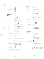
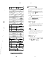
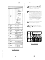
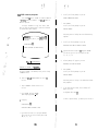
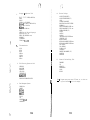
[5j-11 Parallel I/O Ports
Device
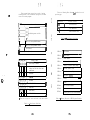
[ 6 ] Expansion Interface Specifications
Z80A PI0
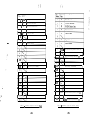
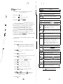
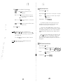
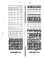
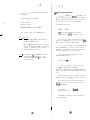
The Formula-l’s Expansion Interface Specifications are
as follows.
* Byte output mode
* Byte input mode
* Byte bi-directional mode (only Port-A)
* 5.25” floppy disk drive8 (FD-3)
* 8” f l o p p y d i s k d r i v e s (FD-8)
* C e n t r o n i c s S t a n d a r d I n t e r f a c e P r i n t e r (FP-80)
* RS-232-C Serfal Interface
* 20mA Current-Loop Serial Interface
* Bigger CRT which is driven by composite video signal. (FM-g)
+- Bit mode
:
,:.
,
* I’
I
., .t .
.,;c”
Port
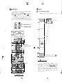
8 bits x 2 ports (Port-A, Port-B)
Handshake Line
2 lines each port (Ready, Strobe)
Interface
TTL l e v e l ( U s i n g C e n t r o n i c s S t a n d a r d
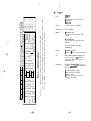
DMA
The DMA transfer requests Break-Out by the in
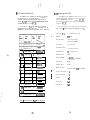
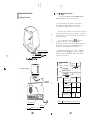
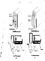
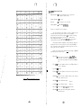
By using connectors on the rear aide, expansion devices
c a n b e c o n n e c t e d d i r e c t l y . Further, Baud-Rate of Serial Ports
and Jumper can be set respectively.
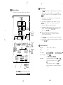
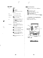
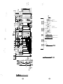
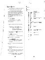
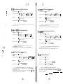
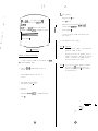
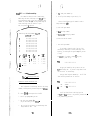
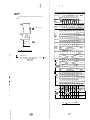
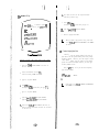
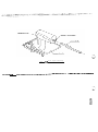
The layout of the rear view is as follows.
Interface as our standard.)
c o m i n g ‘m s i g n a l f r o m o u t s i d e t h e
Therefore, it i s p o s s i b l e t o
system unit.
input to CPU, DMA transfer requests by
specific program.
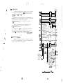
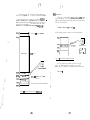
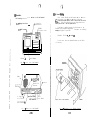
Interruption
Break-Out of Interruption Vector by the
following conditions are only possible with
Fan.
specific program.
/O
0
RS-232~C(CH-B)
Cormstor
* Receiving strobe signal from the external
devices at the byte output mode.
+ Receiving strobe signal from the external
devices at the byte input mode.
L’
r‘.
.
_-
-
Parallel I/O
Connector
Connector
* Receiving strobe signal (for input or
output) from the external devices at the
byte bi-directional mode.
8” Floppy Disu
Drive Connector
.
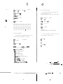
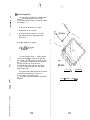
* When the conditions are true at the state
of bit mode.
Jumper, Baud-RatA
\Fuse
Power Switch
5.25” Floppy Dis
Drive Connector J
F i g . 3 : Rear View of the Formula-l
-12-
F
.
AC Connector
-130