1
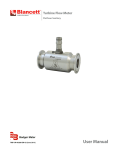
Flow Monitor
B2800 Advanced
DSY-PM-00286-EN-02 (May 2015)
User Manual
Flow Monitor, B2800 Advanced
CONTENTS
Scope of This Manual . . . . . . . . . . . . . . . . . . . . . . . . . . . . . . . . . . . . . . . . . . . . . . . . . . . . . . . . . . . . . . . . . . . .3
Unpacking and Inspection . . . . . . . . . . . . . . . . . . . . . . . . . . . . . . . . . . . . . . . . . . . . . . . . . . . . . . . . . . . . . . . .3
Safety . . . . . . . . . . . . . . . . . . . . . . . . . . . . . . . . . . . . . . . . . . . . . . . . . . . . . . . . . . . . . . . . . . . . . . . . . . . . . 3
Terminology and Symbols . . . . . . . . . . . . . . . . . . . . . . . . . . . . . . . . . . . . . . . . . . . . . . . . . . . . . . . . . . . . . .3
Considerations . . . . . . . . . . . . . . . . . . . . . . . . . . . . . . . . . . . . . . . . . . . . . . . . . . . . . . . . . . . . . . . . . . . . .3
Introduction . . . . . . . . . . . . . . . . . . . . . . . . . . . . . . . . . . . . . . . . . . . . . . . . . . . . . . . . . . . . . . . . . . . . . . . . . 4
Operating the Monitor . . . . . . . . . . . . . . . . . . . . . . . . . . . . . . . . . . . . . . . . . . . . . . . . . . . . . . . . . . . . . . . . . . .5
Buttons . . . . . . . . . . . . . . . . . . . . . . . . . . . . . . . . . . . . . . . . . . . . . . . . . . . . . . . . . . . . . . . . . . . . . . . . . 5
Modes . . . . . . . . . . . . . . . . . . . . . . . . . . . . . . . . . . . . . . . . . . . . . . . . . . . . . . . . . . . . . . . . . . . . . . . . . . 5
Programming . . . . . . . . . . . . . . . . . . . . . . . . . . . . . . . . . . . . . . . . . . . . . . . . . . . . . . . . . . . . . . . . . . . . . . . . 6
Programming Mode . . . . . . . . . . . . . . . . . . . . . . . . . . . . . . . . . . . . . . . . . . . . . . . . . . . . . . . . . . . . . . . . . 6
Return to Run Mode . . . . . . . . . . . . . . . . . . . . . . . . . . . . . . . . . . . . . . . . . . . . . . . . . . . . . . . . . . . . . . . . . 9
Run Mode . . . . . . . . . . . . . . . . . . . . . . . . . . . . . . . . . . . . . . . . . . . . . . . . . . . . . . . . . . . . . . . . . . . . . . . .9
Additonal Scaling Parameters . . . . . . . . . . . . . . . . . . . . . . . . . . . . . . . . . . . . . . . . . . . . . . . . . . . . . . . . . . . . . .9
Flow 4 mA Setting . . . . . . . . . . . . . . . . . . . . . . . . . . . . . . . . . . . . . . . . . . . . . . . . . . . . . . . . . . . . . . . . . . 10
Flow 20 mA Setting . . . . . . . . . . . . . . . . . . . . . . . . . . . . . . . . . . . . . . . . . . . . . . . . . . . . . . . . . . . . . . . . . 10
4…20 mA Calibration . . . . . . . . . . . . . . . . . . . . . . . . . . . . . . . . . . . . . . . . . . . . . . . . . . . . . . . . . . . . . . . 10
4…20 mA Test . . . . . . . . . . . . . . . . . . . . . . . . . . . . . . . . . . . . . . . . . . . . . . . . . . . . . . . . . . . . . . . . . . . . 10
Battery Replacement . . . . . . . . . . . . . . . . . . . . . . . . . . . . . . . . . . . . . . . . . . . . . . . . . . . . . . . . . . . . . . . . . . . 10
Additional Input Options . . . . . . . . . . . . . . . . . . . . . . . . . . . . . . . . . . . . . . . . . . . . . . . . . . . . . . . . . . . . . . . . 11
Additional Scaling Information . . . . . . . . . . . . . . . . . . . . . . . . . . . . . . . . . . . . . . . . . . . . . . . . . . . . . . . . . . . . 12
Pulse Output Signals for Linear Processes . . . . . . . . . . . . . . . . . . . . . . . . . . . . . . . . . . . . . . . . . . . . . . . . . . . 12
Pulse Output Signals for Non-linear Processes . . . . . . . . . . . . . . . . . . . . . . . . . . . . . . . . . . . . . . . . . . . . . . . . 13
Default K-factor Values . . . . . . . . . . . . . . . . . . . . . . . . . . . . . . . . . . . . . . . . . . . . . . . . . . . . . . . . . . . . . . . . . . 13
Troubleshooting Guide . . . . . . . . . . . . . . . . . . . . . . . . . . . . . . . . . . . . . . . . . . . . . . . . . . . . . . . . . . . . . . . . . 14
Part Number Information . . . . . . . . . . . . . . . . . . . . . . . . . . . . . . . . . . . . . . . . . . . . . . . . . . . . . . . . . . . . . . . . 14
Specifications . . . . . . . . . . . . . . . . . . . . . . . . . . . . . . . . . . . . . . . . . . . . . . . . . . . . . . . . . . . . . . . . . . . . . . . 15
Mounting Options and Dimensions . . . . . . . . . . . . . . . . . . . . . . . . . . . . . . . . . . . . . . . . . . . . . . . . . . . . . . . . . 16
Meter Mount . . . . . . . . . . . . . . . . . . . . . . . . . . . . . . . . . . . . . . . . . . . . . . . . . . . . . . . . . . . . . . . . . . . . . 16
Remote Mount . . . . . . . . . . . . . . . . . . . . . . . . . . . . . . . . . . . . . . . . . . . . . . . . . . . . . . . . . . . . . . . . . . . . 16
Swivel Mount . . . . . . . . . . . . . . . . . . . . . . . . . . . . . . . . . . . . . . . . . . . . . . . . . . . . . . . . . . . . . . . . . . . . . 17
Replacement Parts . . . . . . . . . . . . . . . . . . . . . . . . . . . . . . . . . . . . . . . . . . . . . . . . . . . . . . . . . . . . . . . . . . . . 18
Installation Drawing . . . . . . . . . . . . . . . . . . . . . . . . . . . . . . . . . . . . . . . . . . . . . . . . . . . . . . . . . . . . . . . . . . . 19
Page ii
May 2015
Scope of This Manual
SCOPE OF THIS MANUAL
This manual is intended to help you get the B2800 flow monitor up and running quickly.
IIMPORTAN
Read this manual carefully before attempting any installation or operation. Keep the manual accessible for future reference.
UNPACKING AND INSPECTION
Upon opening the shipping container, visually inspect the product and applicable accessories for any physical damage such
as scratches, loose or broken parts, or any other sign of damage that may have occurred during shipment.
NNOTE: If damage is found, request an inspection by the carrier’s agent within 48 hours of delivery and file a claim with the
carrier. A claim for equipment damage in transit is the sole responsibility of the purchaser.
SAFETY
Terminology and Symbols
Indicates a hazardous situation, which, if not avoided, is estimated to be capable of causing death or
serious personal injury.
Indicates a hazardous situation, which, if not avoided, could result in severe personal injury or death.
Indicates a hazardous situation, which, if not avoided, is estimated to be capable of causing minor or
moderate personal injury or damage to property.
Considerations
The installation of the B2800 monitor must comply with all applicable federal, state, and local rules, regulations, and codes.
EXPLOSION HAZARD - SUBSTITUTION OF COMPONENTS MAY IMPAIR SUITABILITY FOR CLASS I, DIVISION 2.
AVERTISSMENT
RISQUE D’EXPLOSION - LA SUBSTITUTION DE COMPOSANTS PEUT RENDRE CEMATÉRIEL INACCCEPTABLE POUR LES
EMPLACEMENTS DE CLASSE I, DIVISION 2.
DO NOT CONNECT OR DISCONNECT EITHER POWER OR OUTPUTS UNLESS THE AREA IS KNOWN TO BE NONHAZARDOUS.
AVERTISSMENT
RISQUE D’EXPLOSION. NE PAS DÉBRANCHER TANT QUE LE CIRCUIT EST SOUSTENSION, À MOINS QU’LL NE S’AGISSE
D’UN EMPLACEMENT NON DANGEREUX.
IIMPORTAN
Not following instructions properly may impair safety of equipment and/or personnel.
May 2015
DSY-PM-00286-EN-02
Page 3
Introduction
INTRODUCTION
The B2800 flow monitor is a state-of-the-art digital signal processing flow monitor, designed to provide exceptional flexibility
at a very affordable price. Though designed for use with Blancett flow meters, this display can be used with almost any flow
meter producing a low amplitude AC output or contact closure signal.
This flow monitor is capable of accepting a low level frequency input for calculating flow rate and total. These calculations
can then be displayed in the specified units of measurement. All B2800 flow monitors are pre-programmed at the factory, if
ordered with a Blancett flow meter. If required, however, the monitor can easily be reconfigured in the field.
The monitor’s large 8-digit by 0.75 in. (19.05 mm) numeric liquid crystal display makes extended range viewing practical. The
second 8-digit by 0.38 in. (9.65 mm) alphanumeric display provides for selectable units viewing in RUN mode and prompts for
variables in program mode. You can display rate or total, or alternate between rate and total.
Page 4
DSY-PM-00286-EN-02
May 2015
Operating the Monitor
OPERATING THE MONITOR
Rate / Total Display
And
Programming Choices
Mode
Indicator
RUN
PROGRAM
RELAY1
RELAY2
Units Display
And
Programming Choices
Programming
Keys
Figure 1: B2800 flow monitor
Buttons
MENU Enters and exits PROGRAM mode
UP
Scrolls forward through the parameter options, increments numeric variables and scrolls
backward through parameters
RIGHT
Scrolls backward through the parameter options, moves the active digit to the right and
scrolls forward through parameters
ENTER
Saves programming information, advances to the next programming parameter, and
used in the reset process
Modes
RUN
Normal operating mode
PROGRAM
Used to program parameters in the display
If your monitor was ordered with a Blancett flow meter, the two components ship from the factory calibrated as a set. If the
monitor is a replacement, the turbine’s K-factor has changed or the monitor is being used with some other pulse generating
device, the monitor must be programmed.
May 2015
DSY-PM-00286-EN-02
Page 5
Programming
PROGRAMMING
Each turbine flow meter is shipped with either a K-factor value or frequency data. If frequency data is provided, the data must
be converted to a K-factor before programming the monitor. K-factor information, when supplied, can usually be found on the
neck of the flow meter or stamped on the flow meter body. The K-factor represents the number of pulses per unit of volume.
The K-factor will be needed to program the monitor readout.
Programming Mode
See Note
Note: Only available when either
KGS or LBS are Selected
x
x
Figure 2: Advanced programming menu
Enter Programming Mode
Press MENU to enter the programming mode. The mode indicator changes from RUN to PROGRAM.
NNOTE: If any input value exceeds the meter’s capabilities for that particular parameter, the LIMIT indicator flashes, indicating
an invalid entry. Press ENTER to return to the parameter’s entry screen to reenter the value.
Select Meter Size
At the METER prompt, press ENTER. The current meter size flashes. If the current setting is correct, press ENTER to advance to
the next parameter. To change the current setting, press UP or RIGHT to scroll to the bore size of your meter. Press ENTER to
save and advance to the DISPLAY parameter.
NNOTE: The meter connection size and the bore size are different. For example, many of the one inch NPT turbines have bore
sizes that range from 3/8…1 in. (9.53…25.4 mm). Use the correct bore size so the meter will report correct flows and
totals.
Select Display Function
The monitor can display RATE or TOTAL or alternate between BOTH rate and total. At the DISPLAY prompt, press ENTER. The
monitor shows the current display mode. To change to an alternate display mode, press UP or RIGHT to scroll to the correct
display mode. Press ENTER to save and advance to the RATE UNT parameter.
Select Units of Measure
At the RATE UNT prompt, press ENTER. The monitor shows the current rate unit. If the current selection is correct, press ENTER
to advance to the next parameter. To change to an alternate unit, press UP or RIGHT to scroll to the correct rate unit. Press
ENTER to save and advance to the RATE INT parameter.
Page 6
DSY-PM-00286-EN-02
May 2015
Programming
Select Rate (Time) Interval
At the RATE INT prompt, press ENTER. The monitor shows the current time interval. If the current selection is correct, press
ENTER to advance to the next parameter. To change to an alternate time interval, press UP or RIGHT to scroll to the correct
time interval. Press ENTER to save and advance to the TOTL UNT parameter.
NNOTE: If flow rate is the only measurement of interest, press RIGHT to advance to the KFAC UNT to complete the
programming process.
Select Units of Measure
At the TOTAL UNT prompt, press ENTER. The monitor shows the current total units. If the current selection is correct, press
ENTER to advance to the next parameter. To change to an alternate unit, press UP or RIGHT to scroll to the correct totalization
unit. Press ENTER to save and advance to the TOTL MUL parameter.
NNOTE: This unit of measure does not have to reflect the rate unit you have previously chosen.
Example: Rate Units = Gallons, Total Units = Barrels
Select Total's Display Multiplier
This parameter displays the accumulated flow total in multiples of 10. For example, if the optimum totalization unit is 1000
gallons, the unit total display increments by one digit for every 1000 gallons monitored. In RUN mode, at 1000 gallons the
total monitor reads 1, at 3000 gallons, the total display reads 3. This feature eliminates having to look at a total, count the
digits, and mentally insert commas for each 1000 multiple.
At the TOTL MUL prompt, press ENTER. The monitor shows the current total multiplier. If the current selection is correct, press
ENTER to advance to the next parameter. To change to an alternate multiplier, press UP or RIGHT to scroll to the correct
multiplier unit. Press ENTER to save and advance to the KFAC UNT parameter.
NNOTE: If pounds or kilograms were chosen as the RATE UNT or TOTL UNT, the monitor advances to the SP GRAV parameter.
Specific Gravity
At the SP GRAV parameter, press ENTER. The first digit of the current specific gravity flashes. If the current setting is correct,
press ENTER to advance to the next parameter. To change the current setting, press RIGHT to move to the correct digit. Press
UP to increment the digit. Repeat for all digits. Press ENTER to save and advance to the KFAC UNT parameter.
Enter Meter's K-Factor Unit
NNOTE: The K-factor supplied with the meter, or calculated from calibration data, is needed to complete this step.
At the KFAC UNT prompt, press ENTER. The display shows the current K-factor unit. If the current selection is correct, press
ENTER to advance to the next parameter. To change the K-factor, press UP or RIGHT to scroll to the correct K-factor. Press
ENTER to save and advance to the SCALE F parameter.
NNOTE: For meters calibrated in gallons, use PUL/GAL; for meters calibrated in cubic meters, use PUL/M3 or any other
unit option.
Scale Factor
The scale factor is used to force a global change to all variables. For example, under operating conditions the display
is reading a consistent three percent below the expected values at all flow rates. Rather than changing all parameters
individually, the scale factor is used to compensate for the three percent offset. Set the scale factor to 1.03 to correct the
readings. The range of scale factors is 0.5…1.5. The default scale factor is 1.0.
At the SCALE F prompt, press ENTER. The first digit of the current scale factor flashes. If the current selection is correct, press
ENTER to advance to the next parameter. To change to an alternate scale factor, press UP to increment the display digit until
it matches the first digit of the new scale factor. Press RIGHT to advance to the next digit. Repeat for all digits. Press ENTER to
save and advance to the METERTYP parameter.
May 2015
DSY-PM-00286-EN-02
Page 7
Programming
Meter Type
At the METERTYP prompt, press ENTER. The current meter type displays. If the current selection is correct, press ENTER
to advance to the next parameter. To change the type, press UP or RIGHT. Press ENTER to save and advance to the next
parameter. If GAS is selected, the operating pressure (psig) and operating temperature (° F) must be entered. If LIQUID is
selected, the monitor advances to the DAMPING parameter.
NNOTE: The 4…20 mA zero and span values are not factory set.
Operating Pressure
At the OP PRES prompt, press ENTER. The first digit of the current setting flashes. If the current setting is correct, press
ENTER to advance to the next paramter. To change the current setting, press RIGHT to move to the correct digit. Press UP to
increment the digit until it matches the new operating pressure. Repeat for all digits. Press ENTER to save and advance to the
OP TEMP parameter.
Operating Temperature
At the OP TEMP prompt, press ENTER. The first digit of the current setting flashes. If the current setting is correct, press
ENTER to advance to the next paramter. To change the current setting, press RIGHT to move to the correct digit. Press UP to
increment the digit until it reaches the new operating temperature. Repeat for all digits. Press ENTER to save and advance to
the DAMPING parameter.
Damping Factor
The damping factor is increased to enhance the stability of the flow readings, and decreased to allow the flow meter to react
faster to changing values of flow. This parameter can be any value 0…99 with 0 being the default.
At the DAMPING prompt, press ENTER. The first digit of the current damping setting flashes. If the current selection is correct,
press ENTER to advance to the next parameter. To change the damping factor, press UP to increment the digit. Press RIGHT
to move to the next digit. After all digits are entered, press ENTER to save and advance to the PULS OUT parameter.
Totalizer Pulse Output
The pulse output parameter can be either enabled or disabled. When enabled, this output generates a 20 mS duration pulse
for every time the least significant digit of the totalizer increments. The amplitude of the pulse is dependent on the voltage
level of the supply connected to the pulse output and is limited to a maximum 30V DC.
Linearization
Linearization enhances the accuracy of the display. The linearization accepts a maximum of ten points and requires additional
calibration data from the meter being used with the monitor. Typically, calibration information can be obtained in three,
five and ten points from the flow meter’s manufacturer. If linearization is not needed, press RIGHT to advance to the next
parameter. To complete linearization, press ENTER at the LINEAR prompt. The meter advances to the NUM PTS parameter.
Number of Points
If the number of points is set to 0, linearization is disabled. Press ENTER. The most significant digit of the number of points
entry begins to flash. The first number can be a 1 or a 0 only. Press UP to increment the first digit. Press RIGHT to move to the
least significant digit. When both digits have been entered, press ENTER to save and advance to the FREQ 1 parameter.
Frequency
At the FREQ 1 prompt, press ENTER. The first digit of the first linear point’s frequency input flashes. If the first frequency is
correct, press ENTER to advance to the next parameter. To change the frequency, press UP to increment the digit. Press
RIGHT to move to the next digit. After all digits are entered, press ENTER to save and advance to the COEFF 1 parameter.
Coefficient
The coefficient is the value applied to the nominal K-factor to correct it to the exact K-factor for that point. The coefficient is
calculated by dividing the actual K-factor for that point by the average K-factor for the flow meter.
Coefficient = Actual K-Factor
Average K-Factor
At the COEFF prompt, press ENTER. The first digit of the coefficient flashes. If the first coefficient is correct, press ENTER
to advance to the next parameter. To change the frequency, press UP to increment the digit. Press RIGHT to move to the
next digit. Repeat for all digits. After all digits are entered, press ENTER to save and advance to the next set of linear points.
Continue entering pairs of frequency and coefficient points until all data has been entered. Press MENU twice at the NUM PTS
prompt to exit to the LINEAR prompt. Press RIGHT to advance to the PASSWORD parameter.
Page 8
DSY-PM-00286-EN-02
May 2015
Additonal Scaling Parameters
Password
The password setting restricts access to PROGRAM mode. Initially, the password is set to all zeros and any user can modify
the paramter settings. To change the password, press ENTER at the PASSWORD prompt. The first digit flashes. Press UP to
increment the digit and RIGHT to advance to the next digit. After entering all digits, press ENTER to store the password and
advance to RST PSWD. The new password is now required to enter PROGRAM mode. With this password set, any user is able to
reset the stored totals on the monitor.
NNOTE: This password will allow the operator to manually reset totals.
Reset Password
The reset password parameter restricts resetting the totals on the monitor. The PASSWORD must also be set to restrict the total
reset. Initially, the password is set to all zeros and any user can reset the stored totals on the monitor. To change the password,
press ENTER at the RST PSWD prompt. The first digit flashes. Press UP to increment the digit and RIGHT to advance to the next
digit. After entering all digits, press ENTER to store the password and return to the METER parameter. The reset pasword is
now required to reset the totals on the monitor.
NNOTE: Entering a password in the PASSWORD screen and leaving the default password in the RST PSWD screen allows for
total resets (not requiring a password), but restricts programming modification.
Return to Run Mode
After entering all parameters, press MENU to return to RUN mode.
Run Mode
Reset Total
To reset the monitor’s total display, in RUN mode, press MENU and ENTER simultaneously until TOTAL RST starts to flash. The
display returns to the RUN mode at the conclusion of the reset procedure.
Store Total
The current total can be manually stored in the monitor’s flash memory. This procedure may be needed prior to changing the
settings or replacing the battery. Press and hold ENTER for two seconds. The display flashes TOTALSVD and then returns to
RUN mode.
Automatic Store Total
The monitor is equipped with a store total feature that works automatically, saving the current total to flash memory. The
frequency of saves depends on the power supply option chosen.
Battery Powered:Once per hour and just before a low battery condition turns the unit off.
Loop Powered: Once every ten minutes.
ADDITONAL SCALING PARAMETERS
x
x
Figure 3: 4…20 mA programming menu
NNOTE: The programming instructions in this section are only available for loop powered units. Battery powered units do not
include these programming parameters.
May 2015
DSY-PM-00286-EN-02
Page 9
Battery Replacement
Flow 4 mA Setting
Zero is the default flow rate at the 4 mA setting. If the current selection is correct, press ENTER to advance to the Flow 20 mA
parameter. To change the setting, press UP to increment the flashing digit and press RIGHT to move to the next digit. Press
ENTER to save and advance to the Flow 20 mA parameter.
Flow 20 mA Setting
The turbine meter’s maximum flow rate is the default value for the 20 mA setting. If the current selection is correct, press
ENTER to advance to the 4…20 mA Calibration parameter. To change the setting, press UP to increment the flashing digit and
press RIGHT to move to the next digit. Press ENTER to save and advance to the 4…20 mA Calibration parameter.
4…20 mA Calibration
The 4…20 mA Calibration parameter is the fine adjustment of the 4…20 mA output. The 4 mA setting is typically between
35…50. To set the 4 mA value, connect an ammeter in series with the loop power supply. At the 4MA OUT prompt, press UP to
increment and RIGHT to decrement the 4 mA value to until a steady 4 mA reading is reached on the ammeter. Press ENTER to
lock in this value and advance to 20MA OUT. The 20 mA adjustment is performed using the same procedure as the
4 mA adjustment.
4…20 mA Test
The monitor contains a diagnostic routine that allows the simulation of mA values between 4…20 to check output tracking.
At the 4-20TEST prompt press UP to increment the simulated mA output or RIGHT to decrement the value in increments of
1 mA. The ammeter should track the simulated mA output. If a 4…20 mA test in not necessary, press ENTER once to escape
the testing at any time.
NNOTE: If you ordered the B2800 flow monitor with a Blancett turbine flow meter, the 4…20 mA was programmed and
factory calibrated.
Mag
Input
2J
Keypad
Connector
JP2
1 2 3 4 5
1
2
3
Pulse
Inuput
4
5
6
+ mA4-20
+
-
DC
+ Out
Pulse
TB1
Freq. In
10…30V DC
1…5V DC
Figure 4: Typical ammeter connection
BATTERY REPLACEMENT
Battery powered monitors use a single 1.5V, D size alkaline battery. When replacement is necessary, use a clean fresh battery
to ensure continued trouble-free operation. It is recommended that the total be saved to memory before the battery
is removed.
1. Unscrew the two captive screws on the front panel to gain access to the battery.
2. Replace the battery, being sure to observe the proper polarity.
3. Refasten the front panel.
Page 10
DSY-PM-00286-EN-02
May 2015
Additional Input Options
ADDITIONAL INPUT OPTIONS
The B2800 flow monitor is capable of receiving magnetic pickup input (small signal sine wave) or a contact closure input
(pulse). Since most Blancett turbine flow meters use a magnetic pickup, the B2800 flow monitor is shipped configured for
magnetic pickup input. To change to a contact closure input, remove JP2 from the top two pins and jumper them to the
bottom two pins. See Figure 6.
Pulse Input Card
30V DC (Max)
1
10K
+
20 mS Pulse
2
3
4
5
6
-
+
-
+
-
+ Pulse In
- Pulse In
Magnetic Pickup
Analog Input Card - 4-20 mA
10…30V DC
(Loop Supply Voltage - 5)
0.02
RMAX =
- Common
Figure 5: Wiring diagram
Loop Powered
Battery Powered
Mag
Input
2J
Keypad
Connector
30V DC (Max)
1
10K
2
+ Out
Pulse
20 mS Pulse
Mag
Input
2J
JP2
1 2 3 4 5
3
4
+ mA4-20
5
+
Pulse
Inuput
Keypad
Connector
-
JP2
1 2 3 4 5
6
Pulse
Inuput
TB1
30V DC (Max)
Freq. In
10K
20 mS Pulse
10…30V DC
1
2
+ Out
Pulse
3
4
5
6
+ mA4-20
+
-
TB1
Freq. In
N/C N/C
1…5V DC
250 Typ
RMAX =
(Loop Supply Voltage - 5)
0.02
Magnetic Pickup
Magnetic Pickup
Figure 6: Circuit board layouts
May 2015
DSY-PM-00286-EN-02
Page 11
Additional Scaling Information
ADDITIONAL SCALING INFORMATION
This information is supplied as a general introduction to the basic concepts used to scale rate displays. The applicability of the
information is dependent on the type and capabilities of the specific display/monitor used.
Flow meters producing an electronic signal are normally supplied in one of two output formats. The pulse format generates
some form of alternating signal that can be raw, that is no amplification or wave shaping can be done prior to transmission to
the readout. The output pulse rate is related proportionally to flow rate. Pulses can also be modified to produce higher output
amplitudes or specific wave shapes.
The other output format is an analog signal. This is a continuous, variable voltage or current signal that is normally scaled to
the dynamic range of the meter. Typical analog signals are 0…5V DC, 0…10V DC, and 4…20 mA. The analog signals may or
may not be derived from a raw pulse signal produced by the flow meter.
Scaling for any of these input signals always requires at least two scaling points for a linear process – zero or minimum flow
point and the maximum flow point. Additionally, each scaling point has two components, the actual input signal value and
the desired display value at that input signal for that scaling point.
For example, a pulse output flow meter has a flow of 50 gpm at a pulse rate of 100 Hz. The actual input signal is the 100 Hz
figure, but allowing the display to read 100 would be meaningless to the operator. The solution to this problem is to scale the
display to read 50 (gpm) when the input is 100 Hz.
Pulse Output Signals for Linear Processes
Pulse output signals are related to flow rate by a constant, usually referred to as the K-factor. The K-factor is reported as the
number of accumulated pulses that represents a particular volume, such as gallon or liter. K-factors are indicated in pulses
per unit volume or counts per unit volume. An example of a K-factor, normally supplied by the manufacturer, might be 2000
counts per gallon. The K-factor is correlated to flow through a simple mathematical relationship:
Frequency = K-factor × Volume per unit of time
60
Using the previous example of 2000 counts per gallon and further assuming this meter has a maximum flow rate of 25 gpm,
the formula can be arranged to calculate the input frequency required for a scaling point as follows:
Frequency =
2000 × 1 (gal)
= 33.333 Hz at 1 gpm
60
Given that the meter has a maximum flow rate of 25 gpm, the maximum frequency would then be:
Frequency =
2000 × 25 (gal)
= 833.333 Hz at 25 gpm
60
A programmable display requires at least two points. The first point is the zero or minimum flow and the second is normally
the maximum flow rate. For the imaginary flow meter used in the example above, the scaling would be as follows:
Page 12
Input Value for Scaling Point 1
=
0
Display Value for Scaling Point 1
=
0
Input Value for Scaling Point 1
=
833.33
Display Value for Scaling Point 2
=
25
DSY-PM-00286-EN-02
May 2015
Default K-factor Values
Pulse Output Signals for Non-linear Processes
Few flow meters actually behave in a linear way. There is always some uncertainty about the exact flow at a given reported
input value. For many common flow measurement applications, the assumption of linear flow is adequate for the process
being measured. When higher accuracy is required, a technique called linearization is often employed.
When the flow meter is being calibrated, multiple data points are obtained for the particular meter being tested. A typical five
point calibration run is displayed below.
GPM (LPM)
Average Frequency
**UUT Hz Counts/GAL
UUT K (Hz × 60)/NK gpm
Error (% FS)
15.00 (59.78)
769.7
3078.59
14.90
–0.65
9.06 (34.3)
466.1
3086.75
9.03
–0.38
5.49 (20.78)
285.2
3118.64
5.52
0.65
3.32 (12.57)
171.7
3103.95
3.32
0.17
2.00 (7.57)
103.6
3101.80
2.01
0.10
**UUT = Unit Under Test
If this meter produced an actual linear output, the K-factor calculation for the Unit Under Test would be exactly the same for
each measurement point. Inspection of the UUT K in the example provided shows that this is not the case and indicates that
this meter is not a perfectly linear device.
Many programmable displays allow for linearization and can provide a better match of the displayed flow values with the
actual flow values by incorporating more measurement points. In the example, the unit would be programmed for six points,
the five data points and a zero point, and use pairs of input values to accomplish the linearization.
DEFAULT K-FACTOR VALUES
Meter Size
Default K-factor
Lower Limit
Upper Limit
3/8 in. (9.53 mm)
20,000
16,000
24,000
1/2 in. (12.7 mm)
13,000
10,400
15,600
3/4 in. (19.05 mm)
2750
2200
3300
7/8 in. (22.23 mm)
2686
2148
3223
1 in. (25.4 mm)
870.0
696.0
1044
1-1/2 in. (38.1 mm)
330.0
264.0
396.0
2 in. (50.8 mm)
52.0
41.6
62.0
3 in. (76.2 mm)
57.0
45.6
68.0
4 in. (101.6 mm)
29.0
23.2
35.0
6 in. (152.4 mm)
7.0
5.6
8.0
8 in. (203.2 mm)
3.0
2.4
4.0
10 in. (254 mm)
1.6
1.3
2.0
May 2015
DSY-PM-00286-EN-02
Page 13
Troubleshooting Guide
TROUBLESHOOTING GUIDE
Issue
No LCD display
No rate or total
displayed
Remedy
• Check battery voltage. Should be 1.5V DC. Replace if low or dead.
• Check connection from meter pickup to display input terminals.
• Check turbine meter rotor for debris. Rotor should spin freely.
• Check programming of flow monitor.
• This is usually an indication of external noise. Keep all AC wires separate from DC wires.
Flow rate display
interprets reading
constantly
• Check for large motors close to the meter pickup.
• Check for radio antenna in close proximity.
• Try disconnecting the pickup from the monitor pig tail. This should stop the noise.
Flow rate indicator
bounces
• This usually indicates a weak signal. Replace pickup and/or check all connections.
• Check K-factor.
PART NUMBER INFORMATION
B 28 A X X - C S
Units of Measure
CS- Customer Selectable
Program Level
A-Advanced
Power Option
B-Battery
L-Loop
Page 14
Mounting Style
M- Meter Mount
R- Remote Mount
S- Swivel Mount
H-Hand-Held
DSY-PM-00286-EN-02
May 2015
Specifications
SPECIFICATIONS
Power Supply Options
Power Consumption
Alphanumeric Rate and
Total Display
Battery Powered
One D size, 1.5V alkaline battery
Loop Powered
Optional 4…20 mA loop power
Battery Powered
Less than 1 milliwatt
Loop Powered
25 mA (maximum)
Eight digit, 0.75 in. (19.05 mm) high numeric display
Eight character, 0.38 in. (9.65 mm) high alphanumeric display
Fixed or toggle modes of operation for flow rate and totalizer display
One pulse for each increment of the least significant totalizer digit
Pulse Output Signal
Inputs
Pulse Type
Opto-isolated open collector transistor
Maximum Voltage
30V DC
Pulse Width
(ON state) 20 mS / max pulse rate 20 Hz
Current
(ON state) 0.9V drop @ 5.0 mA or 0.7V drop @ 0.1 mA
Frequency Range
0…3500 Hz
Trigger Sensitivity
30 mV p-p
Over Voltage Protected
±30V DC
Accuracy
±0.1%
Temperature Drift
50 ppm / ° C (maximum)
Analog Output (Loop
Powered Version)
Type
4…20 mA current loop
Resolution
1:4000
Environmental
Enclosure Rating
Operating Temperature –22…158° F (–30…70° C)
Humidity
0…90% non-condensing
Meter, Remote and
Swivel Mount
NEMA/UL/CSA Type 4X (IP-66)
Transient Over-Voltages Category 3, in accordance with IEC664
Pollution Degree
Certifications
Units of Measure
2, in accordance with IEC664
CSA
Class I, Div 1 Groups C, D; Class II, Div 1 Groups E, F, G; CSA C22.2 No.157-92, UL 913
CE
IEC 61326-1
US Gallons, oil barrels, liters, cubic meters, MGal, cubic ft, mliters, mcf, mmcf, acre ft, liq barrels,
lbs, kgs
Time Intervals
May 2015
Day, hour minute, second
DSY-PM-00286-EN-02
Page 15
Mounting Options and Dimensions
MOUNTING OPTIONS AND DIMENSIONS
Meter Mount
D
C
G dia
B
A
E
F
A
B
C
D
E
F
G dia
9.25 in.
(235.0 mm)
7.00 in.
(177.8 mm)
5.75 in.
(146.0 mm)
4.00 in.
(101.6 mm)
3.45 in.
(87.6 mm)
1.50 in.
(38.1 mm)
0.875 in.
(22.2 mm)
Remote Mount
D
F
E
B
I dia
C
A
G
.25 in. dia
(6.4 mm)
(4 HOLES)
H
A
B
C
D
E
F
G
H
I dia
7.00 in.
(177.8 mm)
2.40 in.
(61.0 mm)
2.25 in.
(57.2 mm)
7.00 in.
(177.8 mm)
5.75 in.
(146.0 mm)
4.38 in.
(111.2 mm))
3.45 in.
(87.6 mm)
1.50 in.
(38.1 mm)
0.875 in.
(22.2 mm)
Page 16
DSY-PM-00286-EN-02
May 2015
Mounting Options and Dimensions
Swivel Mount
C
D
B
A
E
G dia
F
A
B
C
D
E
F
G dia
12.25 in.
(311.2 mm)
7.00 in.
(177.8 mm)
5.75 in.
(146.0 mm)
4.00 in.
(101.6 mm)
3.45 in.
(87.6 mm)
1.50 in.
(38.1 mm)
0.875 in.
(22.2 mm)
May 2015
DSY-PM-00286-EN-02
Page 17
Replacement Parts
REPLACEMENT PARTS
Page 18
Component
Part Number
Keypad
B260713
Battery
B280601
Battery Tie Wrap
B228036
Pickup Cable
B222-121
Desiccant Bag
B260630
PVC Union
B220016
PVC Reducer Bushing
B220056
Rubber Washer
B228207
Steel Lock Washer
B220018
PCB Shield (battery units)
B280603
Desiccant Shield
B280680
Cord Grip
B220103
DSY-PM-00286-EN-02
May 2015
Installation Drawing
A
B
C
F
F
D
G
G
E
H
H
INSTALLATION DRAWING
1
2
A
B
12
DSY-PM-00286-EN-02
C
D
E
12
11
11
10
10
9
9
8
8
7
7
6
6
5
5
4
4
3
3
2
D
59380
1
B280001
B280001
May 2015
Page 19
Flow Monitor, B2800 Advanced
Control. Manage. Optimize.
BLANCETT is a registered trademark of Badger Meter, Inc. Other trademarks appearing in this document are the property of their respective entities. Due to continuous research,
product improvements and enhancements, Badger Meter reserves the right to change product or system specifications without notice, except to the extent an outstanding
contractual obligation exists. © 2015 Badger Meter, Inc. All rights reserved.
www.badgermeter.com
The Americas | Badger Meter | 4545 West Brown Deer Rd | PO Box 245036 | Milwaukee, WI 53224-9536 | 800-876-3837 | 414-355-0400
México | Badger Meter de las Americas, S.A. de C.V. | Pedro Luis Ogazón N°32 | Esq. Angelina N°24 | Colonia Guadalupe Inn | CP 01050 | México, DF | México | +52-55-5662-0882
Europe, Middle East and Africa | Badger Meter Europa GmbH | Nurtinger Str 76 | 72639 Neuffen | Germany | +49-7025-9208-0
Europe, Middle East Branch Office | Badger Meter Europe | PO Box 341442 | Dubai Silicon Oasis, Head Quarter Building, Wing C, Office #C209 | Dubai / UAE | +971-4-371 2503
Czech Republic | Badger Meter Czech Republic s.r.o. | Maříkova 2082/26 | 621 00 Brno, Czech Republic | +420-5-41420411
Slovakia | Badger Meter Slovakia s.r.o. | Racianska 109/B | 831 02 Bratislava, Slovakia | +421-2-44 63 83 01
Asia Pacific | Badger Meter | 80 Marine Parade Rd | 21-06 Parkway Parade | Singapore 449269 | +65-63464836
China | Badger Meter | 7-1202 | 99 Hangzhong Road | Minhang District | Shanghai | China 201101 | +86-21-5763 5412
Legacy Document Number: 02-DSY-PM-00397