1
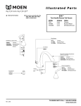
Turbine Flow Meter B142 Gas QuikSert R RACINE, WI USA MODEL XXX-XXX S/N XXXXXXXX CL I DIV 1 GP C,D MAX. WP/T 2220 PSI 15.3 MPa 350°F SINGLE SEAL ® US 215035 C W/ B111113 INSTALLED Vmax = 10V Imax = 3mA Ci = 0µF Li = 1.65H C LA SS IFIE D ELECTRICAL SAFETY E112860 TUR-UM-00272-EN-02 (June 2014) User Manual Turbine Flow Meter, B142 Gas QuikSert Page ii June 2014 User Manual CONTENTS Introduction . . . . . . . . . . . . . . . . . . . . . . . . . . . . . . . . . . . . . . . . . . . . . . . . . . . . . . . . . . . . . . . . . . . . . . . . . 5 Theory of Operation . . . . . . . . . . . . . . . . . . . . . . . . . . . . . . . . . . . . . . . . . . . . . . . . . . . . . . . . . . . . . . . . . . . . 5 Specifications . . . . . . . . . . . . . . . . . . . . . . . . . . . . . . . . . . . . . . . . . . . . . . . . . . . . . . . . . . . . . . . . . . . . . . . . 7 Installation . . . . . . . . . . . . . . . . . . . . . . . . . . . . . . . . . . . . . . . . . . . . . . . . . . . . . . . . . . . . . . . . . . . . . . . . . . 8 Other Factors Affecting Performance . . . . . . . . . . . . . . . . . . . . . . . . . . . . . . . . . . . . . . . . . . . . . . . . . . . . . . .9 Mounting . . . . . . . . . . . . . . . . . . . . . . . . . . . . . . . . . . . . . . . . . . . . . . . . . . . . . . . . . . . . . . . . . . . . . . . .9 Operational Startup . . . . . . . . . . . . . . . . . . . . . . . . . . . . . . . . . . . . . . . . . . . . . . . . . . . . . . . . . . . . . . . . . 10 Calibration . . . . . . . . . . . . . . . . . . . . . . . . . . . . . . . . . . . . . . . . . . . . . . . . . . . . . . . . . . . . . . . . . . . . . . . . . 10 Troubleshooting Guide . . . . . . . . . . . . . . . . . . . . . . . . . . . . . . . . . . . . . . . . . . . . . . . . . . . . . . . . . . . . . . . . . 14 Nominal K Factor Values . . . . . . . . . . . . . . . . . . . . . . . . . . . . . . . . . . . . . . . . . . . . . . . . . . . . . . . . . . . . . . . . . 14 Replacing Turbine Cartridges . . . . . . . . . . . . . . . . . . . . . . . . . . . . . . . . . . . . . . . . . . . . . . . . . . . . . . . . . . . . . 15 Replacement Procedure . . . . . . . . . . . . . . . . . . . . . . . . . . . . . . . . . . . . . . . . . . . . . . . . . . . . . . . . . . . . . . 15 Gas Compensation Considerations . . . . . . . . . . . . . . . . . . . . . . . . . . . . . . . . . . . . . . . . . . . . . . . . . . . . . . . 15 Absolute Pressure and Temperature . . . . . . . . . . . . . . . . . . . . . . . . . . . . . . . . . . . . . . . . . . . . . . . . . . . . . . 15 Effects of Changing Pressures . . . . . . . . . . . . . . . . . . . . . . . . . . . . . . . . . . . . . . . . . . . . . . . . . . . . . . . . . . 16 Effects of Changing Temperatures . . . . . . . . . . . . . . . . . . . . . . . . . . . . . . . . . . . . . . . . . . . . . . . . . . . . . . . 16 Fixed Pressure and Temperature Conversions . . . . . . . . . . . . . . . . . . . . . . . . . . . . . . . . . . . . . . . . . . . . . . . . 16 K factor Calculation in Standard Cubic Feet . . . . . . . . . . . . . . . . . . . . . . . . . . . . . . . . . . . . . . . . . . . . . . . . . . 17 Dynamic Systems . . . . . . . . . . . . . . . . . . . . . . . . . . . . . . . . . . . . . . . . . . . . . . . . . . . . . . . . . . . . . . . . . . 17 Symbol Explanations . . . . . . . . . . . . . . . . . . . . . . . . . . . . . . . . . . . . . . . . . . . . . . . . . . . . . . . . . . . . . . . . . . . 18 Certificate of Compliance . . . . . . . . . . . . . . . . . . . . . . . . . . . . . . . . . . . . . . . . . . . . . . . . . . . . . . . . . . . . . . . . 19 June 2014 Page iii Turbine Flow Meter, B142 Gas QuikSert Page iv June 2014 User Manual INTRODUCTION The B142 gas turbine flow meter is designed with wear resistant moving parts to provide a long service life with very low maintenance. Should the B142 meter be damaged, the turbine is easily replaced in the field with a drop-in repair kit rather than replacing the entire flow meter (see Replacing Turbine Cartridges on page 15 for repair kit information). Repair parts are constructed of stainless steel alloy and tungsten carbide. THEORY OF OPERATION Gas moving through the turbine flow meter causes the rotor to turn at a speed proportional to the flow rate. The rotor blade cuts the magnetic field that surrounds the magnetic pickup, which in turn generates a frequency output signal that is directly proportional to the volumetric flow rate (see Figure 1). The signal is used to represent flow rate and/or totalization of a gas passing through the turbine flow meter and is always expressed as the number of electric pulses that the meter produces per cubic foot. This value, called the K factor, is constant over each flow meter’s range and is unique to the meter. Output Signal Magnetic Pickup Rotor Figure 1: B142 turbine flow meter June 2014 Page 5 Turbine Flow Meter, B142 Gas QuikSert 1” NPT B A R RACINE, WI USA MODEL XXX-XXX S/N XXXXXXXX CL I DIV 1 GP C,D MAX. WP/T 2220 PSI 15.3 MPa 350°F SINGLE SEAL ® US 215035 C W/ B111113 INSTALLED Vmax = 10V Imax = 3mA Ci = 0µF Li = 1.65H C LA SS IFIE D ELECTRICAL SAFETY E112860 C D Figure 2: Dimensions A B C D 2.95 in. (74.9 mm) 3.12 in. (79.2 mm) 3.61 in. (92.0 mm) 1.80 in. (45.7 mm) Magnetic Pickup (B111113) Turbine Assembly Cartridge Retaining Rings (2 Required) Figure 3: Parts identification Page 6 June 2014 User Manual SPECIFICATIONS Physical Installation Mounts between 2 inch ANSI raised face flanges. Horizontal or vertical mounting Flow Range/Nominal K Factors See pressure drop graphs Low Range 7…70 acfm (10…100 mcfd)/365 pulses per acf (12,900 pulses per m3) Mid Range 14…210 acfm (20…300 mcfd)/190 pulses per acf (6710 pulses per m3) High Range 35…350 acfm (50…500 mcfd)/85 pulses per acf (3000 pulses per m3) Working Pressure Vacuum to 2220 psig (15.3 MPa) Pressure Drop 3 inches of water column (7.5 mbar) at maximum rated flow (dry air) Pressure Port 1/8 inch NPTF (plugged) Temperature –40…330° F (–40…165° C) Electrical Output Voltage 100 mVp-p minimum when used with Blancett B111113 magnetic pickup Accuracy Linearity ± 2% of reading over the specified measurement range Uncertainty ± 1% of reading (when calibration data is entered into an intelligent Blancett monitor/transmitter) Repeatability ± 0.5% Certifications Intrinsically Safe Class I Division 1 Groups C, D Entity parameters with Blancett B111113 magnetic pickup installed for US and Canada. Complies with UL 913 and CSA 22.2 No. 157-92 Vmax= 10V Imax = 3 mA Ci = 0 µF Li = 1.65 H Explosion Proof Class I Division 1 Groups C, D. Complies with UL1203 and CSA C22.2 No. 30-M1986 Single Seal Complies with ANSI/ISA 12.27.01-2003 Construction Body and Cartridge 316/316L stainless steel Bearing Mounts 304 stainless steel Set Screws – Pressure Port Plug 316 stainless steel Bearings and Rotor Shaft Tungsten carbide Rotor 410 stainless steel Connections Pickup Mates with AN3106A-10SL Conduit 1 in. NPT (25.4 mm) June 2014 Page 7 Turbine Flow Meter, B142 Gas QuikSert INSTALLATION Before installation, the flow meter should be checked internally for foreign material and to be sure that the rotor spins freely. Gas lines should also be cleared of all debris. The flow meter must be installed with the flow indication arrow, etched on the exterior of the meter body, pointing in the correct direction of flow. The preferred mounting orientation is to have the meter installed in horizontal piping, with the pickup facing upward. However, the meter will function in any position. While the flow meter body and magnetic pickup are sold as separate items, in most instances they are ordered at the same time and come assembled from the factory. If the magnetic pickup was not ordered with the meter body or replacement of the magnetic pickup becomes necessary, all that is needed to install it is to thread the pickup into the pickup port until it is bottomed out. Finger tightening is all that is required for proper installation. The gas that is to be measured must be free from any large particles that may obstruct the rotor from turning. If particles are present, a filter of at least 60 mesh (0.0092 clearance) should be installed upstream before operation of the flow meter. The preferred plumbing setup is one containing a bypass line (see Figure 3) that allows for meter inspection and repair without interrupting flow. If a bypass line is not used, it is important that all control valves be located downstream of the flow meter (see Figure 5). Isolation Valve Flow Straightner (Optional) Display 1 2 QuikSert Turbine Flow Meter Isolation Valve 10 Pipe Diameters Minimum 5 Pipe Diameters Minimum Bypass Line Figure 4: Bypass line installation It is recommended that a minimum length, equal to ten (10) pipe diameters of straight pipe, be installed on the upstream side and five (5) diameters on the downstream side of the flow meter. Otherwise meter accuracy may be affected. Piping should be the same size as the flange size. If adequate straight runs of pipe are not available or if erratic flow readings are experienced, place a bundled-tube flow straightener upstream of the flow meter installation. Flow Straightner (Optional) Display 1 QuikSert Turbine Flow Meter 10 Pipe Diameters Minimum 2 Isolation Valve 5 Pipe Diameters Minimum Figure 5: Installation without bypass line Page 8 June 2014 User Manual Other Factors Affecting Performance Do not locate the flow meter or connection cable close to electronic motors, transformers, sparking devices, high voltage lines, or place connecting cable in conduit with wires furnishing power for such devices. These devices can induce false signals in the flow meter coil or cable, causing the meter to read inaccurately. Severe pulsation and/or severe mechanical vibration will affect accuracy and shorten the life of the meter. Steps should be taken to remedy these conditions if they are present. NNOTE: Incompatible gases will deteriorate internal parts and cause the meter to read inaccurately. Mounting The B142 turbine meter is supplied with two “centering rings” that make installation straightforward. Gaskets and either bolts or threaded rods supplied by the customer are also required. See Figure 4. 1. Insert the bottom two bolts between the mounting flanges and install the nuts loosely. 2. Place the centering rings on the outside diameter of the B142 meter and align the bolt notches. 3. Place the centering rings with the B142 meter installed on the two bottom bolts between the flanges. 4. Insert and center the face gaskets. 5. Insert the remaining bolts and nuts. 6. Tighten the nuts to the flange manufacturer's specifications. If problems arise with the flow meter or monitor, consult the Troubleshooting Guide on page 14. If further problems arise, consult the factory. If the internal components of the turbine flow meter are damaged beyond repair, order replacement turbine cartridges. Pipe Flange Bolt Notch Gasket Centering Ring Bolt Nut Figure 6: Installation using centering rings June 2014 Page 9 Turbine Flow Meter, B142 Gas QuikSert Operational Startup The following practices should be observed when installing and starting the meter. MAKE SURE THAT GAS FLOW HAS BEEN SHUT OFF AND PRESSURE IN THE LINE RELEASED BEFORE ATTEMPTING TO INSTALL THE METER IN AN EXISTING SYSTEM. 1. After meter installation, close the isolation valves and open the bypass valve. 2. Open the upstream isolating valve slowly to eliminate hydraulic shock while charging the meter with gas. Open the valve to full open. 3. Open the downstream isolating valve to permit the meter to operate. 4. Close the bypass valve to a full off position. 5. Adjust the downstream valve to provide the required flow rate through the meter. NNOTE: The downstream valve may be used as a control valve. CALIBRATION The meter is calibrated on clean, dry air at the factory and tagged with a K factor (pulses per cubic foot). All attached electronics have been calibrated to match the flow meter’s K factor. Ensure that the mating factory display is configured to the proper operating pressures and temperatures of your application. The B142 meter can be re-calibrated by any conventional meter proving processes used to calibrate standard meters. The following graphs show how the capacities of the flow meters vary with pressure variations. Separate graphs are provided for high, medium and low flow ranges. Page 10 June 2014 June 2014 High Range 1 (6.9) 10 (6.9) 100 (69) Flow Rate 1000 MCFD (694) (SCFM) 10,000 (6,944) 100,000 (69,444) 10 (69) Pressure PSIG (kPa) 100 (690) Measuring Range vs. System Pressure High Range 1,000 (6,900) User Manual Figure 7: High range flow rates Page 11 Page 12 Mid Range 1 (6.9) 10 (6.9) 100 (69) Flow Rate 1000 MCFD (694) (SCFM) 10,000 (6,944) 100,000 (69,444) 10 (69) Pressure PSIG (kPa) 100 (690) Measuring Range vs. System Pressure Mid Range 1,000 (6,900) Turbine Flow Meter, B142 Gas QuikSert Figure 8: Mid range flow rates June 2014 June 2014 Low Range 1 (6.9) 10 (6.9) 100 (69) Flow Rate 1000 MCFD (694) (SCFM) 10,000 (6,944) 100,000 (69,444) 10 (69) Pressure PSIG (kPa) 100 (690) Measuring Range vs. System Pressure Low Range 1,000 (6,900) User Manual Figure 9: Low range flow rates Page 13 Turbine Flow Meter, B142 Gas QuikSert TROUBLESHOOTING GUIDE Trouble Possible Cause Remedy Incorrect K factor entry Correct K factor Debris on rotor support Clean meter Buildup of foreign material on meter bore Clean meter Incorrect K factor entry Correct K factor Wrong magnetic pickup Use only B111113 pickup Incorrect or missing pressure and/or temperature entries Correct pressure and/or temperature entries Debris on rotor Clean meter and add filter Worn bearing Replace rotor and add filter Erratic system indication, meter alone works well (remote monitor application only) Ground loop in shielding Ground shield one place only. Look for internal electronic instrument ground. Reroute cables away from electrical noise. Indicator shows flow when shut off Mechanical vibration causes rotor to oscillate without turning Isolate meter Erratic indication at low flow, good indication at high flow Rotor has foreign material wrapped around it Clean meter and add filter Rotor not turning Clean rotor or replace rotor cartridge Faulty pickup Replace pickup Broken wire in cable between flow sensor and receiving electronics Repair or replace cable Bypass flow, leak Repair or replace bypass valves, or faulty solenoid valves Meter indicates higher than actual rate Meter indicates lower than actual flow rate No flow indication System works perfect, except indicates lower flow over entire range Table 1: Troubleshooting NOMINAL K FACTOR VALUES Gas Meter Flow Range Nominal K factor Low 7…70 acfm (10…100 mcfd) 365 Medium 14…210 acfm (20…300 mcfd) 190 High 35…350 acfm (50…500 mcfd) 85 Table 2: Gas K factors Page 14 June 2014 User Manual REPLACING TURBINE CARTRIDGES If a turbine is damaged and it becomes necessary to service the meter, repairs are easily accomplished in the field using slide-in replacement cartridges. Cartridge replacement kits come complete with the turbine cartridge and two retaining rings. Size Part Number Low Flow Cartridge B142-20L-Kit Mid Flow Cartridge B142-20M-Kit High Flow Cartridge B142-20H-Kit Replacement Procedure 1. Using a knife edge or a small flat bladed screwdriver, remove both retaining rings. With the retaining rings absent, the old turbine cartridge should be easily removed. 2. Clean any foreign materials from the bore of the meter body that may restrict sliding the new turbine cartridge into place. 3. Replace the downstream retaining ring with one of the new retaining rings supplied in the kit. 4. With the meter body on a flat surface and the downstream end facing down, the direction arrow on the outside of the meter body should also be facing down. Place the turbine cartridge at the opening of the meter body with the arrow on the turbine cartridge facing the same direction as the arrow on the meter body. 5. Rotate the turbine cartridge so that the gap in the cartridge lines up with the magnetic pickup, then squeeze the cartridge to reduce the gap until the cartridge slides into the meter body. NNOTE: In a properly aligned cartridge the pressure port at the bottom of the meter body will also line up with the round hole at the bottom of the turbine cartridge. 6. Install the inlet retaining ring. Gas Compensation Considerations Gaseous fluids measured by the B142 gas turbine meter are compressible and are also affected by temperature changes, as illustrated by the ideal gas law equation: P1 V1 T1 = P2 V2 T2 This equation allows the calculation of gas volumes when the pressure and/or temperature values vary from standard conditions. Standard conditions are generally assumed to be 0 psig and 60° F. Because pressure and temperature have a large impact on the mass of gas moving through the flow meter, both values must be entered into the receiving electronics for accurate gas readings to occur. Absolute Pressure and Temperature The ideal gas law equation shows that the volume of gas is determined by the specific pressure and temperature applied to the gas under running conditions. June 2014 Page 15 Turbine Flow Meter, B142 Gas QuikSert In this equation, the pressure (P) is absolute pressure, that is, the observed gauge pressure plus the atmospheric pressure. The commonly used domestic unit of measure for absolute pressure is pounds per square inch absolute (psia). Atmospheric pressure is considered to be 14.73 psi. Therefore, Absolute pressure (psia) is the sum of the gage pressure plus 14.73. Absolute Pressure = Gage Pressure (psig) + 14.73 The absolute temperature in the equation (T) is expressed in degrees Rankine, which is calculated by adding 459.67 to the temperature in ° F. Absolute Temperature = Observed Temperature (° F) + 459.67 Effects of Changing Pressures For applications where the pressure does not remain constant and “Standard” units of measure must be determined, the degree to which changing pressures affect readings must be known. Relatively small changes in pressure can produce large errors in the calculation of standard volumes, especially at low ambient temperatures. NNOTE: The effect of changing pressure is much greater than the effect of changing temperature. The overall effect of changing temperature and pressure is the algebraic sum of the individual effects. Effects of Changing Temperatures For applications where the temperature does not remain constant, it may be desirable to compensate for large fluctuations in temperature. In many applications, temperature changes will not produce serious measurement errors and can be disregarded. In situations where temperature changes are more extreme, for example seasonal temperature changes from winter to summer, reading accuracy can be adversely affected if the measurement is not adjusted for temperature effects. Fixed Pressure and Temperature Conversions Generally, gas volumes are reported in standard cubic feet but are measured in actual cubic feet. NNOTE: Standard cubic feet and actual cubic feet are equivalent for gases at standard conditions of 0 psi and 60° F. Simple conversions between Actual and Standard measurements are easy if the system pressure and temperature are known. The general conversion formulas are: Standard Cubic Feet = Actual Cubic Feet = Actual Cubic Feet x P a x T s Ps x T a Standard Cubic Feet x P s x T a P a x Ts Where: Pa = system pressure in psia (14.73 + gage pressure) Ps = standard pressure in psia Ta = system temperature in ° R (system temperature in ° F + 459.67) Ts = standard temperature in ° R (standard temperature in ° F + 459.67) = 519.76° R Example 1 One actual cubic foot at a pressure of 90 psig and 85° F is equivalent to how many standard cubic feet? Standard Cubic Feet = 1 x (90+14.73) x 519.67 14.73 x (85 + 459.67) = 104.73 x 519.67 14.73 x 544.67 = 54,425 8,023 = 6.784 This example shows that there are 6.784 standard cubic feet of gas in 1 actual cubic foot of gas at a running pressure of 90 psig and 85° F. Page 16 June 2014 User Manual K factor Calculation in Standard Cubic Feet If the running conditions are held constant, the K factor adjustment for converting actual cubic feet to standard cubic feet will also remain constant. In applications where a direct readout in standard cubic feet is desirable the following formula can be used to determine the K factor for any given set of operating conditions: Adjusted K factor = Factory K factor x P s x T a Pa x Tr Example 2 A 2 inch B142 gas turbine meter has a factory K factor of 190 pulses per actual cubic foot and is installed in an application operating at 100 psig at 80° F. Calculate the adjusted K factor that will allow the downstream electronics to display flow in standard cubic feet. Where: Factory K factor = the K factor from the factory supplied in pulses per acf (actual ft3). Pa = system pressure in psia (14.73 + gage pressure) Ps = standard pressure in psia Ta = system temperature in °R (system temperature in ° F + 459.67) Ts = standard temperature in °R (standard temperature in ° F + 459.67) = 519.76° R Adjusted K factor = 190 x14.73 x (80 + 459.67) (100 + 14.73) x (60 + 459.67) = 190 x 14.73 x 539.67 114.73 x 519.67 1,510,375 = = 25.333 59,622 NNOTE: If a Blancett readout such as the B3000 is being used, entering the operating pressure (Op Pres) and operating temperature (Op Temp) will allow the readout to calculate the adjusted K factor automatically, eliminating the need to do manual conversions. In this example, as long as the pressure and temperature stay at 100 psig and 80° F, a K factor of 25.33 will allow the downstream electronics to display rate and total in scfm. Dynamic Systems In systems where pressure and/or temperature vary constantly, the alternative to extracting scf from acf data is to use of a flow computer and discrete pressure and temperature transducers. Flow Computer A B C D ADVANCE BACKUP CANCLE DEC. PT. 1 2 4 4 5 6 7 8 9 ENT 0 CLR Temperature Sensor Flow Sensor by HEDLAND by HEDLAND ® SENSOR S.N.: 64802 CAL. POINT: 154.9 °F: 12. RANGE: -40 °F - 350 °F OUTPUT: 4 - 20 mA Pressure Sensor RTD R SENSOR S.N.: 64 PRESSURE SENSOR: OUTPUT: 4 - 20 mA RACINE, WI USA MODEL XXX-XXX S/N XXXXXXXX CL I DIV 1 GP C,D MAX. WP/T 2220 PSI 15.3 MPa 350°F SINGLE SEAL ® US 215035 C W/ B111113 INSTALLED Vmax = 10V Imax = 3mA Ci = 0µF Li = 1.65H C LA SSI FIE D ELECTRICAL SAFETY E112860 Figure 10 Typical flow computer inputs June 2014 Page 17 Turbine Flow Meter, B142 Gas QuikSert SYMBOL EXPLANATIONS REFER TO ACCOMPANYING DOCUMENTS. EXPLOSION HAZARD - SUBSTITUTION OF COMPONENTS MAY IMPAIR SUITABILITY FOR CLASS I, DIVISION 2. O NOT CONNECT OR DISCONNECT EITHER POWER OR OUTPUTS UNLESS THE AREA IS KNOWN TO BE NOND HAZARDOUS. IIMPORTAN Not following instructions properly may impair safety of equipment and/or personnel. Electrical Symbols Function Direct Current Alternating Current Earth (Ground) Protective Ground Chassis Ground Symbol Page 18 June 2014 User Manual CERTIFICATE OF COMPLIANCE Certificate: 1667574 Master Contract: 215035 Project: 2428682 Date Issued: July 19,2011 Issued to: Racine Federated Inc. 8635 Washington Ave Racine, WI 53406 USA Attention: William Roeber The products listed below are eligible to bear the CSA Mark shown with adjacent indicators ‘C’ and ‘US’ for Canada and US or with adjacent indicator ‘US’ for US only or without either indicator for Canada only. ® C PRODUCTS CLASS 2258 04 CLASS 2258 84 US Issued by: Edward Foo, C.E.T. - PROCESS CONTROL EQUIPMENT -Intrinsically Safe, Entity -For Hazardous Locations - PROCESS CONTROL EQUIPMENT -Intrinsically Safe, Entity --For Hazardous Locations -Certified to US Standards Class I, Div. 1, Groups C and D; Class II, Div. 1, Groups E, F and G: • Model 280605, Battery Powered B2800 Series Flow Monitor. Intrinsically safe when installed per Drawing NO.B280001 and using Duraeell 1.5 V D-cell (p/n MN 1300) or Energizer 1.5 V (p/n E95). Opto-isolated entity parameters are Vmax = 30 V, Imax = 100 mA, Ci = 0 µF, Li = O. Output to Turbine Flow Meter having Entity Parameters of Voc = 3.5V ; Isc = 1.8mA ; Ca = 15µF ; La = 1.65H. Temperature code T3C at maximum Ambient 70 °C. Enclosure Type 4X. • Model B280606, Loop Powered B2800 Series Flow Monitor. Intrinsically Safe when installed per Drawing No. B280002. Opto-isolated entity parameters are Vmax = 30 V, Imax = 100 mA, Ci = 0.0 µF, Li = 0. 4-20 rnA Current loop entity parameters are Vmax = 30 V, Imax = 100 mA, Ci = 0.5 µF, Li = O. Output to Turbine Flow Meter having Entity Parameters of Voe = 3.5V ; Isc = 1.8mA ; Ca = 15µF ; La = 1.65H. Temperature code T3C at maximum Ambient 70°C. Enclosure Type 4X. DQD 507 Rev. 2009-09-01 June 2014 Page: 1 Page 19 Turbine Flow Meter, B142 Gas QuikSert Certificate: 1667574 Master Contract: 215035 Project: 2428682 Date Issued: July 19,2011 • Turbine Flow Meter, Models BII00 and Bl30 QuikSert, Intrinsically Safe with Entity Parameters Vmax = l0V, Imax = 7mA, Ci = 0µF, Li = 0.9H. “Single Seal”, MWP 5000 PSI (34.5MPa), 350° F. • Gas Turbine Flow Meter, Model Bl42 Series, Intrinsically Safe with Entity Parameters Vmax = l0V, Imax = 3mA, Ci = 0µF, Li = 1.65H. “Single Seal”, MWP 5000 PSI (34.5MPa), 350° F. APPLICABLE REQUIREMENTS CAN/CSA C22.2 No. 0-M91 (R2001) - General Requirements - Canadian Electrical Code, Part II CSA C22.2 No. 142 - Ml987 - Process Control Equipment CSA-C22.2 No. 157-92 - Intrinsically Safe and Non-Incendive Equipment for Use in Hazardous Locations CSA-C22.2 No. 94-M91 - Special Purpose Enclosures UL Std No. 913 -7th Ed. - Intrinsically Safe Apparatus and Associated Apparatus for Use in Class I, II and III, Division 1, Hazardous Locations UL No. 50 - 12th Ed. - Enclosures for Electrical Equipment, Non-Environmental Considerations UL No. 50E - 1st Ed. - Enclosures for Electrical Equipment, Environmental Considerations UL No. 746C - 6th Ed. - Polymeric Materials - Use in Electrical Equipment Evaluations ANSI/ISA-12.27.01-2003 - Requirements for Process Sealing Between Electrical Systems and Flammable or Combustible Process Fluids Page 20 June 2014 User Manual Supplement to Certificate of Compliance Certificate: 1667574 Master Contract: 215035 The products listed, including the latest revision described below, are eligible to be marked in accordance with the referenced Certificate Product Certification History ProjectDate Description 2428682 July 19, 2011 2388024 March 15, 2011 2392258 February 16, 2011 2302190 July 30, 2010 2284108 March 26, 2010 2131250 March 31, 2009 1921676 July 19, 2007 1667574 October 4, 2005 Update to include alternative Gas Turbine Flow Meter, Model B142 Series. Update to cover Turbine Flow Meters Entity Certification. Update to report 1667574 to include additional private label. Update to include “Single Seal Device” Marking. Update to Report 1667574 to include an alternate Battery Holder and Battery Bracket assembly. Update of report to add humidity vent and revise model code scheme (including multiple listing). Update Report 1667574 for alternate construction. 1. Transfer Contents of MC 185535 (Legacy 105056) to MC 215035 & cancel MC 185535 (Legacy 105056); History 1439967 2003/10/08 June 2014 Original certification of Model B2800 Flow Monitor (battery and loop powered) as intrinsically safe for Class I, Groups C, D; Class II, Groups E, F, G. Page 21 Turbine Flow Meter, B142 Gas QuikSert INTENTIONAL BLANK PAGE Page 22 June 2014 User Manual INTENTIONAL BLANK PAGE June 2014 Page 23 Turbine Flow Meter, Gas QuikSert Control. Manage. Optimize. BLANCETT and QuikSert are registered trademarks of Badger Meter, In. Other trademarks appearing in this document are the property of their respective entities. Due to continuous research, product improvements and enhancements, Badger Meter reserves the right to change product or system specifications without notice, except to the extent an outstanding contractual obligation exists. © 2014 Badger Meter, Inc. All rights reserved. www.badgermeter.com The Americas | Badger Meter | 4545 West Brown Deer Rd | PO Box 245036 | Milwaukee, WI 53224-9536 | 800-876-3837 | 414-355-0400 México | Badger Meter de las Americas, S.A. de C.V. | Pedro Luis Ogazón N°32 | Esq. Angelina N°24 | Colonia Guadalupe Inn | CP 01050 | México, DF | México | +52-55-5662-0882 Europe, Middle East and Africa | Badger Meter Europa GmbH | Nurtinger Str 76 | 72639 Neuffen | Germany | +49-7025-9208-0 Europe, Middle East Branch Office | Badger Meter Europe | PO Box 341442 | Dubai Silicon Oasis, Head Quarter Building, Wing C, Office #C209 | Dubai / UAE | +971-4-371 2503 Czech Republic | Badger Meter Czech Republic s.r.o. | Maříkova 2082/26 | 621 00 Brno, Czech Republic | +420-5-41420411 Slovakia | Badger Meter Slovakia s.r.o. | Racianska 109/B | 831 02 Bratislava, Slovakia | +421-2-44 63 83 01 Asia Pacific | Badger Meter | 80 Marine Parade Rd | 21-06 Parkway Parade | Singapore 449269 | +65-63464836 China | Badger Meter | 7-1202 | 99 Hangzhong Road | Minhang District | Shanghai | China 201101 | +86-21-5763 5412 Legacy Document Number: 02-TUR-UM-00012