1
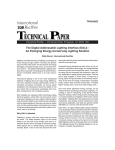
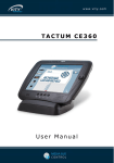
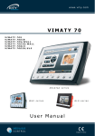
User manual
AMX DALI Connection
With COMM-TEC Gateway
CTG-DALI
For AMX – NetLinx Systems
Version 1
Edition 01.08.2004
© COMM-TEC
Siemensstr. 14
D-73066 Uhingen
www.comm-tec.de
1
Rev. …
1.RANGE OF FUNCTIONS CTG-DALI .......................................................................................... 3
2.INDIVIDUAL STEPS FOR SUCCESSFUL INSTALLATION AND ACTIVATION ...................... 4
2.1 Installation And Cabling DALI System .................................................................................. 4
2.2 Installation DALI Gateway ...................................................................................................... 5
2.3 Installation RS232 Port ........................................................................................................... 5
2.3.1 Pin Assignment .................................................................................................................. 6
PC.................................................................................................................................................... 6
2.4 Activation Of DALI Devices With CTG-DALI-Grouper ......................................................... 6
2.5 Integration Of AMX Driver Software CTDALI For Netlinx Controller.................................. 7
2.5.1 Files On Your Computer .................................................................................................... 7
2.5.2 Communication With The Module ...................................................................................... 7
2.5.3 SYSTEM_CALLs................................................................................................................ 7
2.5.4 Addressing ......................................................................................................................... 8
2.6 Individual AMX Programming ................................................................................................ 8
2.6.1 Direct Control Of Brightness Value .................................................................................... 9
2.6.2 Access Maximum, Minimum Value .................................................................................. 10
2.6.3 Scene Access................................................................................................................... 10
2.6.4 Relative Dimming ............................................................................................................. 11
2.6.5 Set Scene Value .............................................................................................................. 11
2.6.6 Further Access Options.................................................................................................... 12
2.6.7 Acknowledgements .......................................................................................................... 12
2.6.8 Error Analysis ................................................................................................................... 12
3 FURTHER INFORMATION ........................................................................................................ 13
3.1 What Is DALI? Fundamentals, Figures, Data And Facts ................................................... 13
3.2 COMM-TEC DCC2000 DALI Light And Room Control ....................................................... 14
4. APPENDIX ................................................................................................................................ 16
A.
Table 1 - Times................................................................................................................ 16
B.
Table 2 – Dimming Values ............................................................................................. 16
C.
Sample Program ............................................................................................................. 17
2
Rev. …
1.
Range Of Functions CTG-DALI
The following functions and performances for DALI systems are available with the use of COMMTEC gateways CTG-DALI for AMX NetLinx systems:
DALI function description
Addressing of DALI devices (1
system with 64 DALI devices)
Configuration threshold values
Min/Max, system error value,
other threshold values
Definition of groups (up to 16 per
DALI device)
Change of scene values (up to
16 per DALI device)
Access of groups, individual
devices and broadcast with
scene values, relative dimming
and absolute value setting
Set dimmer speed
Set speed for start-up of scenes
Access of DALI Min/Max values
Analysis of acknowledgements
such as lighting error, bus error,
error in DALI device
Operation via HTML
Operation via standard
pushbuttons
Operation via AMX touch panels
CTG-DALI with AMC
control and AMX
driver software
Yes
No
x
x
Remarks
With CTG-DALI and PC with
Windows program CT-DALIGrouper
x
x
x
Also possible with CT-DALIGrouper
x
x
x
x
x
x
With individual programming
x
3
Rev. …
2.
Individual Steps For Successful Installation And Activation
Installation and activation of all hardware and software components takes place in 6 steps:
1) Installation and cabling DALI system
2) Installation DALI gateway
3) Installation RS232 interface
4) Activation DALI devices and CT-DALI-Grouper
5) Integration of driver software
6) Individual AMX programming
Following we defer to the individual steps; not all steps or parts thereof have to be performed by
the AMX supplier. However, the tools provided by COMM-TEC allow for this.
2.1 Installation And Cabling DALI System
An installation company performs the electrical installation according to the regulations for high
voltage current installations. Furthermore, the technical framework, such as the limitation of
maximum participants per DALI line or cable length are to be observed.
The 2-core DALI control cable can be
installed together with the high voltage
current installation and is operated with
low voltage (22.5V DC via CTG-DALI). For
the DALI control cable no additional
electrical installation tools, accessories,
meters or testers are required. No special
data cables have to be used; a common
5x1.5mm2 NYM cable can be used as
power supply cable for EVG and data
cable for DALI. No polarity has to be
observed, each EVG can be accessed
individually, no group cabling is necessary
(see figure 2.1.1).
Fluorescent light
Light bulb
After installation, the DALI system is
addressed and configured, meaning that
each DALI device gets its own address. In
this way each DALI device can be
assigned to max 16 groups. This
configuration is made with the PC
software CT-DALI-Grouper. The CTGDALI can be integrated without further
configuration into an existing DALI system.
In this case the installation company has
to define the group and scene functions. If
the system is not yet configured, go to
chapter 2.2.
Shutters
Figure 2.1.1
4
Rev. …
Technical specifications:
•
•
•
•
•
•
•
•
•
•
•
DALI control cables: e.g. 2-core cable 2x1.5mm2 NYM or any control cable
Max. 64 DALI devices in one system
Max. cable length DALI signal: 300m
DALI power supply 22.5V DC
Max. voltage drop DALI signal: 2V
Max. power consumption DALI system: 250mA
Max. distance DALI EVGs to fluorescent lights in separate array: 2m
Max. distance DALI devices for phase control to light bulbs or halogen (high voltage/low
voltage (power adaptor)): depending on lead resistance
Wiring DALI: delta or series connection
Communication speed 1200 bits/sec
Tolerance of time specification is ±10%.
2.2 Installation DALI Gateway
The DALI gateway is mounted on a DIN rail inside the switchgear cabinet. Terminals D+ and Dare connected to DALI bus. The polarity does not have to be observed.
Terminals “230V” are connected to mains power supply.
SubD9 port (RS232) serves the connection of PC/laptop or AMS control via RS232 port.
DALI bus
Figure 2.2.1
Note:
If using COMM-TEC
interface CTG-DALI no
control unit to be
Mains power supply for
CTG-DALI. Additional
adaptors are not to be
DALI
further DALI
integrated.
DALI via
power
connected.
230V mains power supply
2.3 Installation RS232 Port
The gateway is connected via 5-core cable to serial interface (RS232) of NetLinx master (pin
assignment see 2.3.1).
CAUTION! No further pins to be connected!
The necessary settings of serial AMX interface (baud rate, parity, etc.) are automatically carried
out by AMX module.
5
Rev. …
2.3.1 Pin Assignment
PC
RS232
9-pin SubD
male
Gateway
9-pin SubD
female
Pin
n.c.
2
3
n.c.
5
n.c.
7
8
n.c.
Pin
1
2
3
4
5
6
7
8
9
AMX
Controller
NI series
9-pin SubD
male
Pin
n.c.
2
3
n.c.
5
n.c.
7
8
n.c.
AMX
Controller
all
Description
n.c.
RxD
TxD
n.c.
GND
n.c.
CTS
RTS
n.c.
2.4 Activation Of DALI Devices With CTG-DALI-Grouper
All DALI devices connected via DALI bus have got a short address (0-63) ex factory. Thus with
DALI activation first addressing has to be performed. For this COMM-TEC provides you with the
PC program CTDALI-Grouper.
For individual
steps please
refer to the
separate
manual.
Fluorescent
light
Interface
Light bulb
Configuration and
activation of DALI
system with
COMM-TEC PC
program CT-DALIGrouper
After successful
configuration
connect serial
interface of
AMX NetLinx
control system
to RS232
interface of
DALI gateway
CTG-DALI (pin
assignment see
2.3).
Shutters
Figure 2.1
6
Rev. …
2.5 Integration of AMX Driver Software CTDALI For Netlinx Controller
The supplied CD contains the finished module in compiled runtime version, meaning it is not
available as NetLinx source code. It is integrated in your main program after section
DEFINE_START (see sample program in appendix).
Additionally in section DEFINE_VARIABLE three variables containing status and value messages
and defining the number of EVGs for acknowledgements are to be declared.
2.5.1 Files On Your Computer
By integrating the supplied SYSTEM_CALLs in the main program control functions on DALI bus
are actuated.
For enabling the NetLinx Compiler to integrate the SYSTEM_CALLs, these must be copied
before use into a folder on hard drive. Into which folder they are to be copied depends on the
installation of the AMX software. In standard instillation all SYSTEM_CALLs are stored in folder
“C:\Programme\Gemeinsame Dateien\AMX Share\SYCS”.
Please copy all *.LIB files there.
2.5.2 Communication With The Module
The module demands two addresses – firstly the interface to which the gateway is physically
connected, and secondly a virtual interface, via which the complete communication runs. To
differentiate, the following terms are used:
Physical interface:
Virtual interface:
DEV
vDEV
From the program only the virtual interface is accessed, the physical interface only appears in
section DEFINE_DEVICE and in access of the module.
2.5.3 SYSTEM_CALLs
The package CTDALI1 includes 5 SYSTEM_CALLs to be integrated into the main program for
activation.
The current acknowledgement values and status messages are available in acknowledgement
arrays.
7
Rev. …
2.5.4 Addressing
One DALI line can manage up to 64 bus participants, numbered 0-63 in DALI jargon. In the AMX
world this numbering is changed, so that no individual participant “0” exists.
Furthermore, the groups 1-16 (DALI 0-15) are accessible.
The address 0 serves the global addressing of all participants of a line, meaning:
Address
Description AMX
Term DALI
0
1-64
101-116
broadcast, all participants
EVG 1-64
groups 1-16
broadcast
addresses 0-63
group 0-15
Current brightness values of the maximum 64 addresses can be provided.
Error values (lights/EVGs) can be provided.
2.6 Individual AMX Programming
If you choose not to use SYSTEM_CALLs, all commands may be triggered in virtual device with
SEND_COMMANDs.
Both alternatives are given in the examples. Caution: If using the SEND_COMMANDs the
command syntax has to be carefully observed.
8
Rev. …
2.6.1 Direct Control Of Brightness Value
Brightness values see table 2.
SYSTEM_CALL ‘CT_DALI_1_SetAbs_NX’
Meaning of parameters:
<virtual DALI address>
<DALI address>
<brightness value>
<speed>
(<virtual DALI address>,
<DALI address>,
<brightness value>,
<speed>)
- virtual device address, via which the module
communicates with the gateway
- #0
broadcast
#1-64
individual address
#101-116
group address
- 0-254
(see table 2)
- 0-15
(see table 1)
Examples:
Set all participants of group 3 with maximum speed to maximum value:
Set bus participant #14 (DALI address 13!) within 16 seconds from current to 80% (value from
table 2):
Note:
Alternatively, with SEND_COMMANDs the brightness value can be given as a percentage. The
value input has to be directly followed by “P”.
Set bus participant #14 (DALI address 13!) within 16 seconds from current to 80%:
9
Rev. …
2.6.2 Access Maximum, Minimum Value
SYSTEM_CALL ‘CT_DALI_1_SetMax_NX’
(<virtual DALI address>,
<DALI address>)
(<virtual DALI address>,
<DALI address>)
SYSTEM_CALL ‘CT_DALI_1_SetMin_NX’
Meaning of parameters:
<virtual DALI address>
<DALI address>
- virtual device address (see above)
- #0
broadcast
#1-64
individual address
#101-116
group address
Examples:
Set all participant of group 3 to maximum value:
Set bus participant #14 (DALI address 13!) to maximum value:
2.6.3 Scene Access
Every bus participant can store up to 16 scene values.
SYSTEM_CALL ‘CT_DALI_1_Scene_NX’
Meaning of parameters:
<virtual DALI address>
<DALI address>
<value>
<speed>
(<virtual DALI address>,
<DALI address>,
<value>,
<speed>)
- virtual device address (see above)
- #0
broadcast
#1-64
individual address
#101-116
group address
- scene number (1-15)
- 0-15
(see table 1)
Examples:
Set all participant of group 3 within 2.8 seconds to scene 15:
Set bus participant #14 (DALI address 13!) within 32 seconds to its value for scene 8:
10
Rev. …
2.6.4 Relative Dimming
Continuous change of brightness;
Please remember: the started dimming process must be ended!
Note: these commands for relative dimming do not switch the concerned EVG on or off.
SYSTEM_CALL ‘CT_DALI_1_Dimm_NX’
Meaning of parameters:
<virtual DALI address>
<DALI address>
<direction>
<speed>
(<virtual DALI address>,
<DALI address>,
<direction>,
<speed>)
- virtual device address (see above)
- #0
broadcast
#1-64
individual address
#101-116
group address
- 1 – brighter; 2 – darker; 0 – stop
- 1-15
Examples:
Set all participant of group 3 fast brighter:
:
Stop dimming for bus participant #14 (DALI address 13!):
2.6.5 Set Scene Value
Description of EVG with certain value for a certain scene.
SYSTEM_CALL ‘CT_DALI_1_Set_Scene_Val_NX’
Meaning of parameters:
<virtual DALI address>
<DALI address>
<value 1>
<value 2>
(<virtual DALI address>,
<DALI address>,
<value 1>,
<value 2>)
- virtual device address (see above)
- Caution! Here only individual address valid
#1-64
individual address
- scene number (1-15)
- 0-254
(see table 2)
Examples:
Set scene value #11 of EVG #23 to 100%:
11
Rev. …
2.6.6 Further Access Options
All selectable addresses (0 for broadcast; 1-64 for individual EVGs and 101-116 for the groups)
are mapped directly on levels in the module, meaning they can alternatively be controlled via
command SEND_LEVEL (see example program).
2.6.7 Acknowledgements
With the integration of the module two data fields are created (see example) containing the
acknowledgements of EVGs.
When activated all values below this threshold and > 0 correspond with the minimum value.
The first data field contains the current brightness value of the corresponding EVG; theoretically
values between 0 and 254 are possible. Only theoretically, because most DALI electronic ballasts
have a minimum value of either 1% (corresponds to value 85) or 3% (corresponds to value 126).
The second data field contains possible error messages. The values have the following meaning:
-0
-2
- all other values
- ok
- light fitting error
-bus error / error EVG
2.6.8 Error Analysis
In the module channel 127 can be switched on for error analysis. The monitor displays plain text
messages, which may contain important information.
Proceed as follows:
- Start a monitor connection to master (serial or via Telnet)
- Activate local echo
echo on
- Activate plain text messages msg on
- Activate messages module
on [vdvdali,127]
Now also all control commands for testing may be input via SEND_COMMANDs (description see
above under SYSTEM_CALLs).
Example:
Set all EVGs immediately to minimum value:
Set all EVGs of group 5 to secene value 12 within 2 seconds:
Switch off EVG 1 (DALI #0!) immediately:
12
Rev. …
3
Further Information
3.1 What Is DALI? Fundamentals, Figures, Data And Facts
DALI stands for “Digital Addressable Lighting Interface” and is the definition for the standardized
digital device interface and was created by the manufacturers of these devices.
With this standard the compatibility of device of different manufacturers such as Osram, Tridonic,
Helvar or Philips in a lighting installation is guaranteed.
DALI is not a new system for central building control systems such as LON, EIB or Luxmate but a
meaningful addition for practical application of lighting control. The reason: Systems such as EIB
and LON are designed for much more complex tasks within the building and are thus more
expensive.
With the DALI technology innovative, flexible, easy and cost efficient solutions can be put into
practice. DALI replaces here the 1-10V control technology of electronic ballasts for lighting (EVG)
and will replace them medium-term.
Cabling 1-10V for analog EVG
1-10V voltage
e.g. fluorescent
light
Mains power supply
Figure 1.1
This can be dropped for DALI
compatible devices. Every DALI
device still needs 230V power
supply, but the electronics for
dimming 0-100% a located in the
DALI EVG (figure 1.2). Via the
digital, bi-directional control with
DALI EVGs the actions are actuated
right in the DALI device – with this
also acknowledgement of devices
(e.g. defective light fitting) is
possible. To operate a DALI system
controls are mandatory.
EVGs and other devices such as
transformers are mandatory for
several illuminants, such as
fluorescent lights or halogen
lights. For the dimming of
fluorescent lights controllable
EVGs are mandatory. Until
today so-called analog 1-10V
EVGs were utilized.
Disadvantage: inaccurate control
and costly installations.
Additionally, analog EVGs with
1-10V control need a switched
230V signal e.g. via a relay for
on/off switching (figure 1.1).
Cabling DALI-EVG
Lighting
control
fluorescent
light
Figure 1.2
13
Rev. …
DALI provides among others the following functions:
• Available DALI actuators: EVGs for fluorescent lights, phase control dimmers, shutter
actuators, relays, etc.
• Easy cabling of control wire
• One DALI system consists of:
- max. 64 individual devices
- max. 16 groups
- max. 16 scenes
• Synchronized scene transmissions, meaning all accessed light fittings reach their target
brightness at the same time
• Groups and scene values are stores in the DALI device
• Status display such as light fitting error
• Adjustment of threshold values, dimming speed
• Emergency power features
Further information under: www.dali-ag.org
3.2 COMM-TEC DCC2000 DALI Light And Room Control
The comfort controller for up to three DALI systems powered by AMX manages per device up to 3
DALI systems with 64 DALI devices. The system is a compact solution and needs no
programming. Additionally, each controller integrates 4 relays for room functions such as shutters
and 4 inputs for key control-sections or sensors. The configuration of the DALI system, change of
operating settings, scene values etc. takes place via PC web browser and HTML interface via
integrated AMX web
server.
The controls work
separately as light and
room controls. Several
DCC2000 can be
networked via
Ethernet for buildingwide solutions.
System bus
Integration of EIB,
LON is optional.
As control concept a
certain number of
DALI control unit
standard pushbuttons
Shutters
(32), AMX touch
panels (4) or LCD
Door openers
Light or
keypads (4) can be
motion
sensors
employed.
Air con
Screen
DALI
world 3
DALI
world 2
14
DALI world 1 with
up to 64 DALI
devices
Rev. …
The following functions and features for DALI systems are available with the COMM-TEC
DCC2000 DALI light and room control:
DALI function
Addressing of DALI devices (up
to 3 systems with 64 DALI
devices each)
Configuration threshold values
Min/Max, system error value,
other threshold values
Definition of groups (up to 16 per
DALI device)
Change of scene values (up to
16 per DALI device)
Access of groups, individual
devices and broadcast with
scene values, relative dimming
and absolute value setting
Dimmer speed setting
Scene value speed setting
Access of DALI Min/Max values
Analysis of acknowledgements
such as light fitting errors, bus
errors, errors DALI device
HTML configuration and operator
page
Operation via HTML
Operation via standard
pushbuttons
Operation via AMX touch panels
DCC2000
Yes
No
x
Remark
x
x
x
For the function setting not
programming is necessary. This is
included in the DCC2000 software.
Configuration via Ethernet (PC)
with HTML pages of DCC2000
DALI controller (web server
integrated).
x
x
x
x
x
x
x
x
x
15
Rev. …
4.
Appendix
A.
Table 1 - Times
Times for the setting of absolute values or scenes
Value
0
1
2
3
4
5
6
7
8
9
10
11
12
13
14
15
Duration
< 0.7 sec
0.7 sec
1.0 sec
1.4 sec
2.0 sec
2.8 sec
4.0 sec
5.6 sec
8.0 sec
11.3 sec
16.0 sec
22.6 sec
32.0 sec
45.2 sec
64.0 sec
90.5 sec
B.
Table 2 – Dimming Values
Luminous flux
Digital dimming value
0%
0.1%
0.5%
1.0%
3%
5%
10%
20%
30%
40%
50%
60%
70%
80%
90%
100%
0
1
60
85
126
144
170
195
210
220
229
235
241
246
250
254
$00
$01
$3C
$55
$7E
$90
$AA
$C3
$D2
$DC
$E5
$EB
$F1
$F6
$FA
$FE
16
Rev. …
C.
Sample Program
Here the gateway is physically connected
Communication via this address
Number of EVGs
Current values
Current states
Set all EVGs immediately to max. value
Set all EVGs immediately to min. value
17
Rev. …
- Select duration for setting of scene
or absolute value
- Select speed for relative dimming
Speed 2-10
Set scene
Set scene 1
Set scene 2
Group 3 set direct values with selected speed
brighter
darker
18
Rev. …
Set all EVGs via bar graph
Text output on panel
(for first 10 EVGs)
Selected speed / duration
19
Rev. …