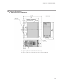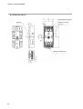
1
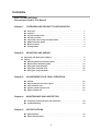
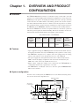
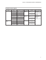
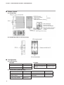
No. CP-SP-1074E
FRS100
Multiburner Control
User's Manual
Thank you for purchasing the FRS100
Multiburner Control.
This manual contains information for
ensuring the correct use of the FRS100.
It also provides necessary information
for installation, maintenance, and troubleshooting.
This manual should be read by those
who design and maintain equipment
that uses the FRS100. Be sure to keep
this manual nearby for handy reference.
RESTRICTIONS ON USE
This product has been designed, developed and manufactured for general-purpose
application in machinery and equipment.
Accordingly, when used in applications outlined below, special care should be taken to
implement a fail-safe and/or redundant design concept as well as a periodic
maintenance program.
• Safety devices for plant worker protection
• Start/stop control devices for transportation and material handling machines
• Aeronautical/aerospace machines
• Control devices for nuclear reactors
Never use this product in applications where human safety may be put at risk.
NOTICE
Be sure that the user receives this manual before the product is used.
Copying or duplicating this user’s manual in part or in whole is forbidden. The information and specifications in this manual are subject to
change without notice.
Considerable effort has been made to ensure that this manual is free
from inaccuracies and omissions. If you should find an error or omission, please contact Yamatake Corporation.
In no event is Yamatake Corporation liable to anyone for any indirect,
special or consequential damages as a result of using this product.
©1999 Yamatake Corporation ALL RIGHTS RESERVED
SAFETY PRECAUTIONS
■ About Icons
The safety precautions described in this manual are indicated by various icons.
Please be sure you read and understand the icons and their meanings described
below before reading the rest of the manual.
Safety precautions are intended to ensure the safe and correct use of this product, to prevent injury to the operator and others, and to prevent damage to property. Be sure to observe these safety precautions.
WARNING
Warnings are indicated when mishandling this
product might result in death or serious injury.
CAUTION
Cautions are indicated when mishandling this
product might result in minor injury to the user, or
only physical damage to the product.
■ Examples
Use caution when handling the product.
The indicated action is prohibited.
Be sure to follow the indicated instructions.
i
WARNING
Use this device for batch operation of the burner (at least one start and
stop in a 24-hour period). Do not use for continuous burner operation
(nonstop combustion for 24h or longer).
This device does not have the prepurge and ignition sequencing functions required for burner ignition. Use this device as part of a system
whose design gives careful consideration to the prepurge timer and
sequence timing, following established safety guidelines.
Wire terminals 1 and 2 so that they receive power continuously whenever the power switch is turned on. This is absolutely necessary to
ensure operation of the self-check circuits at startup.
Therefore, do not wire a thermostat between the power switch and terminal 1 or 2. Doing so might cause a serious combustion equipment
accident.
Connect loads (ignition transformer, solenoid valve, etc.) directly to the
output terminals of this device. If they are not directly connected, combustion safety cannot be ensured.
Do not allow the pilot or main burner "Safety Time" (ignition trial time)
to exceed the specifications of the burner or equipment manufacturer.
If they do, fuel may accumulate in the combustion chamber and form
an explosive air-fuel mixture, resulting in a serious explosion hazard.
Before wiring, mounting, or removing this device, be sure to turn the
power off. Wiring with the power on can result in an electric shock.
Do not connect a solenoid valve to the high voltage side of the circuit.
If a ground fault occurs, the ground fault current may energize and
open the solenoid valve. This device will not be able to prevent the
valve from opening and fuel from flowing out.
Even after the power to this device is turned off, terminal F continues
to hold an electrical charge. To avoid electrical shock, do not touch terminal F.
Carry out the pilot turndown test carefully. If the flame detector is set
so that it detects a pilot flame that is too small to ignite the main burner, this device will not be able to detect a flame failure in the main burner. In that case, fuel will continue to be supplied, causing a serious
explosion hazard.
Before the pilot turndown test or ignition spark response test, make
sure that all manual fuel valves are closed.
ii
WARNING
If the pilot turndown test must be carried out repeatedly, completely
shut down all equipment each time the test is finished, and completely
discharge unburned gas or fuel that has accumulated in the ducts and
combustion chamber. Failure to discharge unburned gas or fuel may
result in an explosion.
When the pilot turndown test is complete, turn OFF the power switch to
shut down the power. Restore all test jumpers and limit interlock/regulator settings to their previous states. If operation begins without the
above steps, damage to the equipment, gas leak or explosion may
result.
Do not start regular operation of the equipment without first completing the trial-run adjustments for this device, as well as the tests specified by the equipment manufacturer.
To prevent electric shock, turn the power off and discharge terminals F
and G before removing this device from the subbase. Use lead wires to
connect terminals F and G of the flame simulator (FSP300C100) to terminals F and G of this device for 10 seconds or more.
CAUTION
Installation, wiring, inspection, adjustment, etc. should be carried out
by a trained and experienced technician who has knowledge and
technical skills related to combustion equipment and flame safeguard
control devices.
Do not install where exposed to any of the following:
• Certain chemicals or corrosive gases (ammonia, sulfur, chlorine,
ethylene compounds, acid, etc.)
• Splashing water or excessive humidity
• High temperatures
• Prolonged vibration
If timers and auxiliary relays are needed for additional functions, select
ones with high reliability, and be sure to design the circuit correctly.
When installing and wiring, be sure to follow the instructions in this
manual and in the user's manual for the combustion equipment.
Make sure the flame detector does not detect ultraviolet rays other
than those of the burner flame. If the flame detector responds to other
ultraviolet rays, it will report that there is a flame even if the burner
flame goes out. As a result, fuel will continue to be discharged,
causing a very serious explosion hazard.
iii
CAUTION
Follow all applicable regulations when doing the wiring work.
Connect the blue signal lead from the Minipeeper Ultraviolet Flame
Detector to terminal 5 and the white lead to terminal 6. Turning on the
power when the flame detector is incorrectly wired could damage the
UV tube.
Run the high-voltage ignition transformer cable separately and keep it
at least 10 cm away from this device.
Make sure that ignition transformer high-voltage cables are properly
connected to prevent faulty contact. Faulty contact might generate
high-frequency radio waves which can cause malfunction.
The ignition transformer ground lead should be connected directly to
the burner body or to a metallic part electrically connected to the
burner body.
Keep power lines and ignition transformer high-voltage cables
separate from the flame detector wires.
Always supply electric power at the voltage and frequency stated on
the model label of this device.
Always connect the power supply last. Otherwise, touching a terminal
accidentally could result in electric shock or damage.
In keeping with technical standards for electrical equipment, the burner
body must have an earth ground connection with a resistance of less
than 100 Ω.
After the wiring is complete, be sure to check that it is correct.
Incorrect wiring may cause damage or faulty operation.
Make sure that the flame detector does not detect the ignition spark. If
the flame detector can detect the spark, change the detector's line of
sight or change the ignition electrode's position.
Only an experienced technician who has knowledge and technical
skills related to combustion equipment and combustion safety should
carry out the pilot turndown test.
This product is equipped with functions that are extremely important
for the safe operation of combustion equipment. Carefully follow the
instructions for its use that are given in this user's manual.
iv
CAUTION
If the safety shutoff has been activated, check all of the items on the
checklists in Chapter 3, ADJUSTMENTS FOR TRIAL OPERATION
before restarting the equipment.
Check the flame current at least once per month. Doing so can prevent
shutdowns caused by a weak flame current signal.
This device has an operating life. Assuming that the operating life of
the combustion equipment used with this device is longer, be sure to
do periodic maintenance and replacement of this device.
In the event that this device is replaced, do all of the checks listed in
Chapter 3, ADJUSTMENTS FOR TRIAL OPERATION.
When doing a maintenance inspection of the burner, be sure to do the
pilot turndown test. Inspection must be done at least once a year.
Conduct periodic inspections in accordance with the user's manual of
the equipment manufacturer.
When cleaning the burner, clean the flame detector as well.
Do not transport this device while it is mounted on a DIN rail. Remove
it from the subbase and pack it in its original box. If it is transported
while on a DIN rail, it might fall off and be damaged.
v
Conventions Used in This Manual
The following conventions are used in this manual:
Handling Precautions:
Handling Precautions indicate items that the user should pay attention to
when handling the FRS100.
Note:
(1), (2), (3):
Notes indicate information that might benefit the user.
Numbers within parentheses indicate steps in a sequence or parts of an
explanation.
vi
Contents
SAFETY PRECAUTIONS
Conventions Used in This Manual
Chapter 1.
OVERVIEW AND PRODUCT CONFIGURATION
■
■
■
■
■
■
■
■
Chapter 2.
Overview • • • • • • • • • • • • • • • • • • • • • • • • • • • • • • • • • • • • • • • • • • • • • • • • • • • • • • • • • • • • • • • • • 1
Features • • • • • • • • • • • • • • • • • • • • • • • • • • • • • • • • • • • • • • • • • • • • • • • • • • • • • • • • • • • • • • • • • 1
System configuration • • • • • • • • • • • • • • • • • • • • • • • • • • • • • • • • • • • • • • • • • • • • • • • • • • • • 1
Security function • • • • • • • • • • • • • • • • • • • • • • • • • • • • • • • • • • • • • • • • • • • • • • • • • • • • • • • • • 2
Precautions for facility instrumentation• • • • • • • • • • • • • • • • • • • • • • • • • • • • • • • • • • 2
Model selection guide • • • • • • • • • • • • • • • • • • • • • • • • • • • • • • • • • • • • • • • • • • • • • • • • • • • • 3
Names of parts • • • • • • • • • • • • • • • • • • • • • • • • • • • • • • • • • • • • • • • • • • • • • • • • • • • • • • • • • • • 4
Configuration • • • • • • • • • • • • • • • • • • • • • • • • • • • • • • • • • • • • • • • • • • • • • • • • • • • • • • • • • • • • 4
MOUNTING AND WIRING
2-1 Mounting and Wiring the Subbase • • • • • • • • • • • • • • • • • • • • • • • • • • • • • • • • • • • • • • • • • • • 5
2-2 Wiring• • • • • • • • • • • • • • • • • • • • • • • • • • • • • • • • • • • • • • • • • • • • • • • • • • • • • • • • • • • • • • • • • • • • • • • • 8
■ Manual ignition (intermittent pilot) • • • • • • • • • • • • • • • • • • • • • • • • • • • • • • • • • • • • • • • 9
■ Burner flame monitoring only • • • • • • • • • • • • • • • • • • • • • • • • • • • • • • • • • • • • • • • • • • 14
■ Wiring the flame detector • • • • • • • • • • • • • • • • • • • • • • • • • • • • • • • • • • • • • • • • • • • • • • • 19
■ Wiring the solenoid valve • • • • • • • • • • • • • • • • • • • • • • • • • • • • • • • • • • • • • • • • • • • • • • • 20
■ Wiring the surge absorber • • • • • • • • • • • • • • • • • • • • • • • • • • • • • • • • • • • • • • • • • • • • • • 21
Chapter 3.
ADJUSTMENTS FOR TRIAL OPERATION
■
■
■
■
■
Chapter 4.
Outline • • • • • • • • • • • • • • • • • • • • • • • • • • • • • • • • • • • • • • • • • • • • • • • • • • • • • • • • • • • • • • • • • • 22
How to measure the flame signal • • • • • • • • • • • • • • • • • • • • • • • • • • • • • • • • • • • • • • • 23
Pilot turndown test • • • • • • • • • • • • • • • • • • • • • • • • • • • • • • • • • • • • • • • • • • • • • • • • • • • • • 24
Ignition spark response test • • • • • • • • • • • • • • • • • • • • • • • • • • • • • • • • • • • • • • • • • • • • 26
Safety shutoff test • • • • • • • • • • • • • • • • • • • • • • • • • • • • • • • • • • • • • • • • • • • • • • • • • • • • • • 27
MAINTENANCE AND INSPECTION
■ Frequency of maintenance and inspection • • • • • • • • • • • • • • • • • • • • • • • • • • • • • 28
■ Troubleshooting • • • • • • • • • • • • • • • • • • • • • • • • • • • • • • • • • • • • • • • • • • • • • • • • • • • • • • • • 29
Chapter 5.
SPECIFICATIONS
■ Specifications • • • • • • • • • • • • • • • • • • • • • • • • • • • • • • • • • • • • • • • • • • • • • • • • • • • • • • • • • • 32
■ External dimensions • • • • • • • • • • • • • • • • • • • • • • • • • • • • • • • • • • • • • • • • • • • • • • • • • • • • 33
vii
Chapter 1.
OVERVIEW AND PRODUCT
CONFIGURATION
■ Overview
The FRS100 Multiburner Control is a combustion safety control with a safe-start
circuit, for use with manually ignited combustion equipment. To ensure safety, the
FRS100 prevents ignition if anything abnormal is detected at start up, and shuts
off the fuel valve if a flame failure occurs during operation. It is used in conjunction with an ultraviolet flame detector or flame rod for batch operation of a burner.
For continuous burner operation (nonstop combustion for 24h or longer), instead of
the FRS100, use the AUR350C, which has a continuous self-checking function.
Because the FRS100 does not have an ignition function, it is used for systems in
which an operator ignites the burner manually. This device should be used in combination with external instrumentation that supplies a purge function.
Key Characteristics of the FRS100
Compatible
burner
operation
type
Purge
function
Ignition
function
Flame
monitoring
Batch
No
No
Yes
Behavior if
flame failure
occurs
Does not
recycle
Compatible
flame
detectors
• Ultraviolet
sensor
• Flame rod
■ Features
• Upon equipment startup, the FRS100 checks both itself and the flame detector.
If anything abnormal is detected, the FRS100 prevents ignition to ensure safety.
• The FRS100 is designed to be compact, and can be plugged into the wiring
sub-base. The sub-base can be mounted by screws or onto a DIN rail.
• The power supply state and ignition detection can be verified easily from the
LEDs on the front display. Completion of the start check is indicated by the
LED on the center of the body behind the front cover.
• Flame voltage output (0 to 5Vdc) can be checked by the FSP136A100, or
continuously monitored by a panel meter or recorder.
• The FRS100 has a dedicated connector so that the optional FRS60A Flame
Meter can be attached.
■ System configuration
In terms of the overall system, the FRS100 serves as the flame monitoring device.
It is used as shown in the diagram below.
High limit controller
Temperature
controller
Air pressure
lower interlock
FRS100
Air
PS
Flame
detector
L
PS
PS L
Fuel
MV
Gas pressure
lower interlock
Exhaust
T/C T/C
Combustion
chamber
H
MV
PV PV
IG
Gas pressure
upper interlock
Ignition Combustion equipment
transformer
1
Chapter 1. OVERVIEW AND PRODUCT CONFIGURATION
■ Security function
The FRS100 is designed to ensure safety, and plays an important safety role by
monitoring the burner operation and the flame.
1. Combustion monitoring and safety shutoff
• Detects flame failure in the burner and quickly shuts off the fuel and shuts
down the burner.
• When an ignition failure, flame failure or flame-out occurs, the FRS100 follows a fixed sequence in shutting down each piece of equipment.
2. Startup, operation, and shutoff of combustion equipment
• The FRS100 operates each device according to a predetermined sequence
and timing.
3. Safe startup
• At every startup signal, the FRS100 checks for false flame in the flame detector and flame detection circuit.
• If a problem is detected, the FRS100 does not start the burner.
4. Redundant design
• Maintains safety even if its own self-check circuit fails.
• Will not deviate from the proper ignition sequence.
■ Precautions for facility instrumentation
In designing facilities that use combustion safety devices, be sure to give careful
consideration to the safety guidelines listed below.
• For safety standards for industrial facilities using combustion equipment, see the
technical guidelines published by the Ministry of Health, Labour and Welfare
• For general safety rules for industrial combustion furnaces, see JIS B 8415.
• For technical safety guidelines for gas combustion furnaces in industrial use, see
publications by the Japan Gas Association.
● Important points for ensuring safety
1. Connect the load directly to the FRS100.
2. Design the interlock so that it can directly cut off power to the load.
3. Be sure to use a safe startup circuit upon startup.
4. Do not set up a bypass, such as manual operation, for any load.
5. Have a redundant main valve and pilot valve.
● Precautions for system design
Since the FRS100 does not have purge or ignition functions, they must be provided externally.
2
Chapter 1. OVERVIEW AND PRODUCT CONFIGURATION
■ Model selection guide
Model
Standard model
High-sensitivity
model
Model No.
Rated power supply
FRS100B100
100Vac
50 / 60Hz
FRS100B200
200Vac
50 / 60Hz
FRS100B104
100Vac
50 / 60Hz
FRS100B204
200Vac
50 / 60Hz
FRS100C100
100Vac
50 / 60Hz
FRS100C200
200Vac
50 / 60Hz
FRS100C104
100Vac
50 / 60Hz
FRS100C204
200Vac
50 / 60Hz
FRS100C150
100Vac
50 / 60Hz
FRS100C250
200Vac
50 / 60Hz
FRS100C154
100Vac
50 / 60Hz
FRS100C254
200Vac
50 / 60Hz
Power
consumption
3W max.
Flame failure
response
Flame detector
3 ±1s
(flame voltage 2V)
Flame Rod
C7007A, C7008A
2s max.
(flame voltage 2V)
Ultraviolet Flame
Detector
C7012A, C7012C
7W max.
3 ±1s
Minipeeper
(flame voltage 4.2V) Ultraviolet Flame
Detector
2s max.
C7035A, C7027A
(flame voltage 4.2V)
7W max.
3 ±1s
(flame voltage 3.5V)
2s max.
(flame voltage 3.5V)
3
Chapter 1. OVERVIEW AND PRODUCT CONFIGURATION
■ Names of parts
● FRS100 body
● FRS50A100 subbase (sold separately)
■ Configuration
● Flame Detector
FRS100B
Name
FRS100C
Model No.
Ultraviolet Flame Detector
C7012A/C
Flame Rod
C7007A, C7008A
Name
Model No.
Minipeeper Ultraviolet Flame C7035A, C7027A
Detector
● Optional Parts (sold separately)
Name
4
Model No.
Name
Model No.
Subbase
FRS50A100
Flame Meter
RS60A
Flame simulator for
C7035A, C7027A
FSP300
Flame Simulator for
Flame Rod
123514A, 121708
Lightning surge absorber
83968019-001
Chapter 2.
2 - 1
MOUNTING AND WIRING
Mounting and Wiring the Subbase
CAUTION
Do not install where exposed to any of the following:
• Certain chemicals or corrosive gases (ammonia, sulfur, chlorine, ethylene
compounds, acid, etc.)
• Splashing water or excessive humidity
• High temperatures
• Prolonged vibration
Do not transport this device while it is mounted on a DIN rail. Remove it from
the subbase and pack it in its original box. If it is transported while on a DIN
rail, it might fall off and be damaged.
When installing and wiring, be sure to follow the instructions in this manual
and in the user's manual for the combustion equipment.
● Mounting location
Maintain space around the control as shown below for heat radiation, and to facilitate mounting, removal, wiring and maintenance.
Above: 50mm min.
Above: 50mm min.
PRS 100 FLAM
E RELAY
POWER
FLAME
PRS 100 FLAM
E RELAY
PRS 100 FLAM
E RELAY
POWER
POWER
FLAME
FLAME
20mm min.
20mm min.
20mm min.
20mm min.
Below: 20mm min.
Below: 20mm min.
Gang-mounting
Stand-alone mounting
Handling Precautions
• If there is room, leave as much space as possible between the FRS and
other FRS units to allow for heat radiation.
• If ambient temperature is close to the allowable upper limit, reduce the
internal temperature of the control panel by mounting a panel cooler or a
cooling fan.
Allowable ambient temperature upper limits
• Gang-mounting: 45°C
• Stand-alone mounting: 60°C
5
Chapter 2. MOUNTING AND WIRING
● Mounting direction
• Mount a vertical plane so that the arrow on the subbase is facing upwards.
• Mount so that the display panel is upward.
PRS 100 FLA
ME RE LAY
POWER
Indicator
FLAME
• Do not mount below direction.
● DIN rail mounting
(1) Pull the DIN rail mounting plate downwards.
(2) Place the subbase on the DIN rail so that the arrow on the subbase is facing
upwards.
(3) Push in DIN rail mounting plate into the DIN rail.
UP
UP
Pull down
6
Place the subbase
UP
Push the DIN rail
mounting plate into
the DIN rail
Chapter 2. MOUNTING AND WIRING
(4) Wire the subbase terminals as instructed in 2-2 Wiring.
(5) Pull the bottom of the controller cover downwards to remove.
(6) Press the controller into the subbase with the display facing upwards.
(7) Tighten the mounting screw on the center of the body to fix onto the subbase
with a maximum torque of 0.3N•m.
FRS100
Subbase
Push the FRS100
into the subbase
E LAY
FRS 100 FLAME R
POWER
UP
FLAME
E LAY
FRS 100 FLAME R
POWER
FLAME
Tighten the screw
and fix
Cover
Flame voltage
meter terminals
(8) If necessary, wire the flame voltage meter terminals.
(9) Mount the cover on the control body.
● Direct panel mounting
(1) Drill two M4 mounting holes in the panel so that the arrow on the subbase will
be facing upward.
32
UP
M4 (2 locations)
(2) Attach the subbase to the panel using two M4 screws at a maximum torque of
0.7N•m.
(3) Wire the subbase terminals as instructed in 2-2 Wiring.
(4) Pull the bottom of the controller cover downwards to remove.
(5) Press the controller into the subbase with the display facing upwards.
(6) Tighten the mounting screw on the center of the body to fix onto the subbase
with a maximum torque of 0.3N•m.
(7) If necessary, wire the flame voltage meter terminals.
(8) Mount the cover on the control body.
Handling Precautions
• Do not tighten the subbase mounting screws using a torque exceeding
the maximum torque. Doing so might damage the subbase.
7
Chapter 2. MOUNTING AND WIRING
2 - 2 Wiring
WARNING
Wire terminals 1 and 2 so that they receive power continuously whenever the
power switch is turned on. This is absolutely necessary to ensure operation
of the self-check circuits at startup.
Therefore, do not wire a thermostat between the power switch and terminal 1
or 2. Doing so might cause a serious combustion equipment accident.
Connect loads (ignition transformer, solenoid valve, etc.) directly to the output
terminals of this device. If they are not directly connected, combustion safety
cannot be ensured.
CAUTION
If timers and auxiliary relays are needed for additional functions, select ones
with high reliability, and be sure to design the circuit correctly
Make sure the load connected to each terminal does not exceed the rating
indicated in the specifications.
When installing and wiring, be sure to follow the instructions in this manual
and in the user's manual for the combustion equipment.
Follow all applicable regulations when doing the wiring work.
Run the high-voltage ignition transformer cable separately and keep it at
least 10 cm away from this device.
Make sure that ignition transformer high-voltage cables are properly
connected to prevent faulty contact. Faulty contact might generate highfrequency radio waves which can cause malfunction.
The ignition transformer ground lead should be connected directly to the
burner body or to a metallic part electrically connected to the burner body.
Keep power lines and ignition transformer high-voltage cables separate from
the flame detector wires.
Always supply electric power at the voltage and frequency stated on the
model label of this device.
Always connect the power supply last. Otherwise, touching a terminal
accidentally could result in electric shock or damage.
In keeping with technical standards for electrical equipment, the burner body
must have an earth ground connection with a resistance of less than 100 Ω.
After the wiring is complete, be sure to check that it is correct. Incorrect
wiring may cause damage or faulty operation.
8
Chapter 2. MOUNTING AND WIRING
■ Manual ignition (intermittent pilot)
High voltage side
Ground side
Interlock contact
normal status
Emergency
stop switch Operation switch
Starting purge
102X
100X
Stop switch
Purge timer
100X
100T
102X
During purge
100T
101X
Purge completion
100T
102X
Power
1
2
Power circuit
1K
Ignition switch
Start check circuit
Purge
completion
102X
7
Start contact
Operation
input circuit
1K
2K
(F)
(G)
5
6
8
Pilot valve
4
Main valve
2K
3
Limit
Flame detector
Ignition
transformer
Flame
amplifier circuit
Internal circuit
–
A
B
Combusiton
lamp
Flame voltage
0-5Vdc
+
Subbase
Handling Precautions
• When the high voltage side is distinguishable from the ground side, connect the high voltage side to terminal 1 and the ground side to terminal 2.
9
Chapter 2. MOUNTING AND WIRING
● Explanation of operation
• Normal operation and shutdown
No
1
2
3
4
5
6
Input status
FRS100 activity
Power ON
Receives power across terminals 1 and 2.
Push-button
If the system is ready for operation, with interlock
operation switch ON contacts in their normal state (closed), when the
operation button is pushed, the prepurge begins.
When the time preset for the purge timer (100T)
has elapsed, the purge completion relay (102X) is
energized.After the prepurge ends, the FRS100
accepts the following operations:
Start contacts ON
If the limit switch status is normal (contacts closed),
pushing the start button applies power across
terminals 7 and 2. Then, after completion of the
start check, relay 1K turns on.
Ignition switch ON When the ignition switch is pushed (contacts closed),
terminal 8 supplies power to the pilot valve and
ignition transformer. The ignition transformer turns
on and the pilot valve opens.
The flame detector detects the pilot burner flame.
Relay 2K turns on. When relay 2K turns on, power
is supplied through terminal 4 and the combustion
lamp lights up.
Ignition switch OFF The N.O. contacts of the ignition switch open, cutting
power to the ignition transformer, which turns off.
Since power is supplied through relays 1K and 2K,
power through terminal 4 continues to maintain the
operation of the pilot valve. When the ignition
switch is turned off, its N.C. contacts close, supplying power to the main valve, which opens.
Start contacts OFF The power applied across terminals 7 and 2 is cut,
relay 1K turns off, and the power to terminal 4 is
also cut. The pilot valve and main valve close and
the combustion lamp turns off.
All loads are de-energized, and when the flame
detector detects the flame failure, relay 2K turns off.
The FRS100 returns to standby status and waits
for the next start signal.
(3)Start contacts ON
(2)Operation switch
(1)Power ON
Start check (2s)
(4)Ignition switch
Flame detection
(5)Ignition switch
OFF (5-10s)
Output activity
(POWER LED lights up)
Purge completion (102X)
(Start check operation LED
lights)
• Ignition transformer ON
• Pilot valve opens
• (FLAME LED lights)
• Combustion lamp lights
• Ignition transformer OFF
• Pilot valve continues
open
• Main valve opens
• Pilot valve closes
• Main valve closes
(FLAME LED turns off)
• Combustion lamp turns
off
• (Start check operation
LED turns off)
(6)Start contacts OFF
Interlock contact
Operation switch
Stop switch
Purge timer 100T
During purge 101X
Purge completion 102X
Start contact (term.7-2)
Ignition transformer
Pilot valve
Main valve
Combustion lamp
POWER LED
FLAME LED
Start check LED
10
Elapsed time
Chapter 2. MOUNTING AND WIRING
• Ignition failure
No
1
2
3
4
5
6
Input status
FRS100 activity
Power ON
Receives power across terminals 1 and 2.
Push-button
If the system is ready for operation, with interlock
operation switch ON contacts in their normal state (closed), when the
operation button is pushed, the prepurge begins.
When the time preset for the purge timer (100T)
has elapsed, the purge completion relay (102X) is
energized.After the prepurge ends, the FRS100
accepts the following operations:
Start contacts ON
If the limit switch status is normal (contacts closed),
pushing the start button applies power across
terminals 7 and 2. Then, after completion of the
start check, relay 1K turns on.
Ignition switch ON When the ignition switch is pushed (contacts closed),
terminal 8 supplies power to the pilot valve and
ignition transformer. The ignition transformer turns
on and the pilot valve opens.
If the pilot burner fails to ignite, the flame detector
cannot detect the pilot burner flame, and relay 2K
does not turn on.
Ignition switch OFF Since the ignition switch contacts are open, power
to the ignition transformer is cut, and ignition
transformer operation stops.
Because relay 2K did not turn on, the voltage at
terminal 4 is zero, and the pilot valve returns
closed. Voltage is also not supplied to the main
valve, so it does not open.
Start contacts OFF Power across terminals 7 and 2 is cut, and relay
1K turns off.
The FRS100 returns to standby status and waits
for the next start signal.
(3)Start contacts ON
(2)Operation switch
(1)Power ON
Start check (2s)
(4)Ignition switch
No flame detection
(5)Ignition switch
OFF (5-10s)
Output activity
(POWER LED lights up)
Purge completion (102X)
(Start check operation LED
lights)
• Ignition transformer ON
• Pilot valve opens
• Ignition transformer OFF
• Pilot valve closes
(Start check operation
LED turns off)
(6)Start contacts OFF
Interlock contact
Operation switch
Stop switch
Purge timer 100T
During purge 101X
Purge completion 102X
Start contact (term.7-2)
Ignition transformer
Pilot valve
Main valve
Combustion lamp
POWER LED
FLAME LED
Start check LED
Elapsed time
11
Chapter 2. MOUNTING AND WIRING
• Flame failure during combustion
No
1
2
3
4
5
6
7
Input status
FRS100 activity
Power ON
Receives power across terminals 1 and 2.
Push-button
If the system is ready for operation, with interlock
operation switch ON contacts in their normal state (closed), when the
operation button is pushed, the prepurge begins.
When the time preset for the purge timer (100T)
has elapsed, the purge completion relay (102X) is
energized.After the prepurge ends, the FRS100
accepts the following operations:
Start contacts ON
If the limit switch status is normal (contacts closed),
pushing the start button applies power across
terminals 7 and 2. Then, after completion of the
start check, relay 1K turns on.
Ignition switch ON When the ignition switch is pushed (contacts closed),
terminal 8 supplies power to the pilot valve and
ignition transformer. The ignition transformer turns
on and the pilot valve opens.
The flame detector detects the pilot burner flame.
Relay 2K turns on. When relay 2K turns on, power
is supplied through terminal 4 and the combustion
lamp lights up.
Ignition switch OFF The N.O. contacts of the ignition switch open, cutting
power to the ignition transformer, which turns off.
Since power is supplied through relays 1K and 2K,
power through terminal 4 continues to maintain the
operation of the pilot valve. When the ignition
switch is turned off, its N.C. contacts close, supplying power to the main valve, which opens.
Flame failure occurs Relay 2K turns off after the flame response period,
the voltage that was supplied from terminal 4 is cut
off, the pilot valve and the main valve close, and
the combustion lamp turns off.
Start contacts OFF Power across terminals 7 and 2 is cut, and relay
1K turns off.
The FRS100 returns to standby status and waits
for the next start signal.
(3)Start contacts ON
(2)Operation switch
(1)Power ON
Output activity
(POWER LED lights up)
Purge completion (102X)
(Start check operation LED
lights)
• Ignition transformer ON
• Pilot valve opens
• (FLAME LED lights)
• Combustion lamp lights
• Ignition transformer OFF
• Pilot valve continues
open
• Main valve opens
• (FLAME LED turns off)
• Pilot valve closes
• Main valve closes
• Combustion lamp turns off
(Start check operation
LED turns off)
Start check (2s)
Flame failure
(4)Ignition switch
Flame response
Flame detection
(6)Start contacts
(5)Ignition switch
OFF
OFF (5-10s)
Interlock contact
Operation switch
Stop switch
Purge timer 100T
During purge 101X
Purge completion 102X
Start contact (term.7-2)
Ignition transformer
Pilot valve
Main valve
Combustion lamp
POWER LED
FLAME LED
Start check LED
Elapsed time
12
Chapter 2. MOUNTING AND WIRING
• False flame detection during startup
No
1
2
3
4
5
6
Input status
FRS100 activity
Power ON
Receives power across terminals 1 and 2.
Push-button
If the system is ready for operation, with interlock
operation switch ON contacts in their normal state (closed), when the
operation button is pushed, the prepurge begins.
When the time preset for the purge timer (100T)
has elapsed, the purge completion relay (102X) is
energized.After the prepurge ends, the FRS100
accepts the following operations:
Start contacts ON
When the limit switch is in a normal state (contacts
closed), pushing the start button applies power
across terminals 7 and 2. The start check is
carried out, but relay 1K does not turn on because
a false flame is detected.
Ignition switch ON Even though the ignition switch contacts are
closed, no voltage is applied to terminal 8, and so
the ignition transformer and the pilot valve do not
operate.
Ignition switch OFF The ignition switch contacts open, and relays 1K
and 2K remain off. No voltage is supplied from
terminal 4, and the load is not energized.
Start contacts OFF The power across terminals 7 and 2 is cut off, and
the FRS100 returns to standby status and waits
for the next start signal.
(3)Start contacts ON
Flame detection
(2)Operation switch
Start check (2s)
Output activity
(POWER LED lights up)
Purge completion (102X)
(FLAME LED lights up)
(FLAME LED turns off)
(6)Start contacts OFF
(1)Power ON
Interlock contact
Operation switch
Stop switch
Purge timer 100T
During purge 101X
Purge completion 102X
Start contact (term.7-2)
Ignition transformer
Pilot valve
Main valve
Combustion lamp
POWER LED
FLAME LED
Start check LED
Elapsed time
13
Chapter 2. MOUNTING AND WIRING
■ Burner flame monitoring only
(In a case where the FRS100 is not used in its usual combustion safety role of
shutting valves, etc.)
High voltage side
Ground side
Power
1
2
Power circuit
2K
Start contact
Start check circuit
7
1K
Contact output
common
(G)
2K
5
6
8
Start check
completion
4
Flame output
2K
3
(F)
Flame detector
Operation
input circuit
Flame
amplifier circuit
Internal circuit
–
A
B
Flame voltage
0-5Vdc
+
Subbase
Handling Precautions
• When the high voltage side is distinguishable from the ground side, connect the high voltage side to terminal 1 and the ground side to terminal 2.
14
Chapter 2. MOUNTING AND WIRING
● Explanation of operation
• Normal operation
No
1
2
Input status
Power ON
Start contacts ON
3
Flame detection
4
Start contacts OFF
FRS100 activity
Power is applied across terminals 1 and 2.
Pressing the start contact supplies power across
terminals 7 and 2. After completion of the start
check, relay 1K turns on. Since relay 1K turns on,
the start check completion output from terminal
8 turns on.
The flame detector detects the flame of the pilot
burner. Relay 2K turns on. Since relay 2K turns on,
the flame output from terminal 4 turns on.
The power supplied across terminals 7 and 2 is
cut off, relay 1K turns off, and the power to
terminals 4 and 8 is also cut off. The start check
completion output and flame output turn off.
Since the flame detector detects a flame failure,
relay 2K turns off. The FRS100 returns to standby
status and waits for the next start signal.
(1)Power ON
(2)Start contacts ON
Start check (2s)
Output activity
(POWER LED lights)
• (Start check operation
LED lights up)
• Start check completion
output turns on
• (FLAME LED lights up)
• Flame output ON
• (Start check LED turns
off)
• Start check completion
output OFF
• (FLAME LED turns off)
• Flame output OFF
(4)Start contacts OFF
(3)Flame detection
Start contact (term.7-2)
Start check completion
Flame output
POWER LED
FLAME LED
Start check LED
Elapsed time
15
Chapter 2. MOUNTING AND WIRING
• Ignition failure
No
1
2
Input status
Power ON
Start contacts ON
3
Ignition failure
4
Start contacts OFF
FRS100 activity
Power is applied across terminals 1 and 2.
Pressing the start contact supplies power across
terminals 7 and 2. After completion of the start
check, relay 1K turns on. Since relay 1K turns on,
the start check completion output from terminal
8 turns on.
If the burner does not ignite, the flame detector
does not detect a burner flame, and relay 2K does
not turn on.
The power supplied across terminals 7 and 2 is
cut off, relay 1K turns off, power to terminals 4
and 8 is cut off, and the start check completion
output turns off.
The FRS100 returns to standby status and waits
for the next start signal.
(1)Power ON
(2)Start contacts ON
Start check (2s)
Output activity
(POWER LED lights)
• (Start check operation
LED lights up)
• Start check completion
output turns on
• (Start check LED turns
off)
• Start check completion
output OFF
(4)Start contacts OFF
Start contact (term.7-2)
Start check completion
Flame output
POWER LED
FLAME LED
Start check LED
Elapsed time
16
Chapter 2. MOUNTING AND WIRING
• Flame failure during combustion
No
1
2
3
4
5
Input status
Power ON
Start contacts ON
FRS100 activity
Power is applied across terminals 1 and 2.
Pressing the start contact supplies power across
terminals 7 and 2. After completion of the start
check, relay 1K turns on. Since relay 1K turns on,
the start check completion output from terminal
8 turns on.
Flame detection
The flame detector detects the flame of the pilot
burner. Relay 2K turns on. Since relay 2K turns on,
the flame output from terminal 4 turns on.
Flame failure occurs After the flame response period, relay 2K turns off,
the voltage supplied from terminal 4 is cut off, and
the flame output turns off.
Start contacts OFF The power supplied across terminals 7 and 2 is
cut off, relay 1K turns off, power to terminals 4 and
8 is cut off, and the start check completion output
turns off.
The FRS100 returns to standby status and waits
for the next start signal.
(1)Power ON
(2)Start contacts ON
Start check (2s)
(3)Flame
detection
Output activity
(POWER LED lights)
• (Start check operation
LED lights up)
• Start check completion
output turns on
• (FLAME LED lights up)
• Flame output ON
• (FLAME LED turns off)
• Flame output OFF
• (Start check LED turns
off)
• Start check completion
output OFF
(4)Flame failure
Flame response
(5)Start contacts OFF
Start contact (term.7-2)
Start check completion
Flame output
POWER LED
FLAME LED
Start check LED
Elapsed time
17
Chapter 2. MOUNTING AND WIRING
• False flame is detected at startup
No
1
2
Input status
Power ON
Start contacts ON
3
Start contacts OFF
FRS100 activity
Output activity
Power is applied across terminals 1 and 2.
(POWER LED lights)
By pushing the start contacts, power is applied
(FLAME LED lights)
across terminals 7 and 2. The start check is
carried out, and relay 1K does not turn on because
a false flame is detected.
Power across terminals 7 and 2 is cut off. The
(FLAME LED turns off)
FRS100 returns to standby status and waits for
the next start signal.
(1)Power ON
Flame detection
(2)Start contacts ON
Start check (2s)
(3)Start contacts OFF
Start contact (term.7-2)
Start check completion
Flame output
POWER LED
FLAME LED
Start check LED
Elapsed time
18
Chapter 2. MOUNTING AND WIRING
■ Wiring the flame detector
CAUTION
Connect the blue signal lead from the Minipeeper Ultraviolet Flame Detector
to terminal 5 and the white lead to terminal 6. Turning on the power when the
flame detector is incorrectly wired could damage the UV tube.
● Wiring between the C7035/C7027 Minipeeper Ultraviolet Flame Detector and the FRS100C
C7035A
C7027A
Terminal 5 (F) Blue
Terminal 5 (F) Blue
Terminal 6 (G) White
Terminal 6 (G) White
•
Allowable lead length
• Type of signal lead
2mm2, 600Vac IV (indoor vinyl) insulated power
lead
Approx. 200m
• Allowable lead length
● Wiring between the Flame Rod and the FRS100B
Flame rod
(F)
Terminal 5
(G)
•
Allowable lead length
• Type of signal lead
• Allowable lead length
Terminal 6
High-frequency coaxial cable 5C2V, 7C2V
Approx. 30m
● Wiring between the C7012A, C7012C Ultraviolet Flame Detector and the FRS100B
C7012C
C7012A
Terminal 5
Terminal 6
•
Blue
(F)
Yellow
Black
Black
(G)
Allowable lead length
• Type of signal lead
• Allowable lead length
Power
Terminal 5
Terminal 6
(F)
(G)
5
4
6
3
1
2
Power
High-frequency coaxial cable 5C2V, 7C2V
Approx. 50m
19
Chapter 2. MOUNTING AND WIRING
■ Wiring the solenoid valve
CAUTION
Do not connect a solenoid valve to the high voltage side of the circuit. If a
ground fault occurs, the ground fault current may energize and open the
solenoid valve. This device will not be able to prevent the valve from opening
and fuel from flowing out.
● Correct connection
100V
Burner
Power
Flame relay
FRS100
Ground side (G)
N
(Ground fault)
L
Combustion unit
High voltage side (H)
Valve (closed)
Fuel
Ground current will not flow to the solenoid valve if the valve is wired as shown in
the figure above, even if faulty insulation on the voltage side (H) causes a ground
fault. Accordingly, the valve will not open, eliminating the risk of fuel discharge.
● Wrong connection
(Ground fault)
100V
Burner
Power
Flame relay
FRS100
Ground side (G)
N
L
Combustion unit
High voltage side (H)
Valve (open)
Fuel
Ground current will flow to the solenoid valve if the valve is wired as shown in the
figure above and if a ground fault occurs. Accordingly, the solenoid valve will open
regardless of the flame relay, causing fuel discharge.
20
Chapter 2. MOUNTING AND WIRING
■ Wiring the surge absorber
Wire as shown below when using a surge absorber (model No.83968019-001,
ordered separately) for protection from lightning surge.
Handling Precautions
• Use a JIS C 3306, 0.75mm2 power lead (lead diameter 0.18, 30-strand)
or higher for wiring to the power supply.
• Attach a Faston receptacle (#187, made by AMP) to one end of the
power lead, and make the wire connection as short as possible.
• Ground the surge absorber mounting bracket by attaching to a grounded
metal part such as the burner body.
21
Chapter 3.
ADJUSTMENTS FOR TRIAL
OPERATION
WARNING
Do not allow the pilot or main burner "Safety Time" (ignition trial time) to
exceed the specifications of the burner or equipment manufacturer. If they do,
fuel may accumulate in the combustion chamber and form an explosive airfuel mixture, resulting in a serious explosion hazard.
Even after the power to this device is turned off, terminal F continues to hold
an electrical charge. To avoid electrical shock, do not touch terminal F.
Before the pilot turndown test or ignition spark response test, make sure that
all manual fuel valves are closed.
Do not start regular operation of the equipment without first completing the
trial-run adjustments for this device, as well as the tests specified by the
equipment manufacturer.
CAUTION
Installation, wiring, inspection, adjustment, etc. should be carried out by a
trained and experienced technician who has knowledge and technical skills
related to combustion equipment and flame safeguard control devices.
Check the flame current at least once per month. Doing so can prevent
shutdowns caused by a weak flame current signal.
■ Outline
The following table shows the test adjustment items described in this chapter:
Item
Applicable Unit
Flame signal measurement method
All units
Pilot turndown test
Units using the pilot burner
Ignition spark response test
All units
Safety shutdown test
All units
Handling Precautions
•
After adjusting the above items, make sure that all of the adjustment
requirements are satisfied. All of the adjustment requirements must be
satisfied by the final mounting position of the flame detector.
● Required equipment
• Tester (input impedance, 100kΩ or more)
Range: 0 to 300Vac, 0 to 5Vdc
• Two jumper leads with crocodile clips, AWG14 (2mm2) or more, approximately
30cm long.
• Insulation tester: 500Vdc megger
● Preliminary inspection
• Check all connections.
• Make sure that the controller is mounted at a location within the allowable ambient temperature.
22
Chapter 3. ADJUSTMENTS FOR TRIAL OPERATION
• Make sure that the flame detector is properly mounted.
(Refer to its instruction manual.)
• Disconnect the loads and flame detector wiring. Measure the insulation resistance across the terminals and panel ground, and make sure that the resistance is
50MΩ or more using an insulation tester or megger of 500Vdc or more.
• Check that all fuel valves and cocks are closed, and the combustion chamber has
been completely vented.
■ How to measure the flame signal
Handling Precautions
• When using the high-sensitivity model, limit the flame voltage to 4.5V or
less.
(1) Start the controller, and measure the flame voltage for each burner under various conditions (at startup, normal operation, etc.).
(2) When measuring the flame voltage, insert the tester probes into the holes to connect to terminals A and B at the bottom front of the controller as shown below.
FRS100 FLAME RELAY
POWER
FLAME
Terminal A
Terminal B
Tester
Input impedance, 100kΩ or more
Black
Red
+
–
0 to 5Vdc range
(3) Refer to the following table for voltage values:
Recommended flame voltage
Checklist
• Make sure that flame monitoring is correct.
2Vdc min.
• The viewing window of the flame detector
must be free of dirt.
• The monitoring tube must not be blocked
with soot.
(4) If the flame signal fluctuates, check the flame detector mounting position and
wiring again.
23
Chapter 3. ADJUSTMENTS FOR TRIAL OPERATION
■ Pilot turndown test
This test is intended to check that the flame is reliably transferred to the main burner when the flame detector detects the pilot flame, even if gas pressure and air pressure change to their worst conditions.
WARNING
Do not allow the pilot or main burner "Safety Time" (ignition trial time) to
exceed the specifications of the burner or equipment manufacturer. If they
do, fuel may accumulate in the combustion chamber and form an explosive
air-fuel mixture, resulting in a serious explosion hazard.
Carry out the pilot turndown test carefully. If the flame detector is set so that it
detects a pilot flame that is too small to ignite the main burner, this device will
not be able to detect a flame failure in the main burner. In that case, fuel will
continue to be supplied, causing a serious explosion hazard.
Before the pilot turndown test or ignition spark response test, make sure that
all manual fuel valves are closed.
If the pilot turndown test must be carried out repeatedly, completely shut
down all equipment each time the test is finished, and completely discharge
unburned gas or fuel that has accumulated in the ducts and combustion
chamber. Failure to discharge unburned gas or fuel may result in an
explosion.
When the pilot turndown test is complete, turn OFF the power switch to shut
down the power. Restore all test jumpers and limit interlock/regulator settings
to their previous states. If operation begins without the above steps, damage
to the equipment, gas leak or explosion may result.
CAUTION
Only an experienced technician who has knowledge and technical skills
related to combustion equipment and combustion safety should carry out the
pilot turndown test.
Handling Precautions
• If a fuel pressure limit switch is used, and its contacts are open, turn it
ON with a jamper cable during this test.
● Test procedure
(1) Turn the operation switch OFF.
(2) Close the manual valves to stop the gas supply to the pilot burner and main
burner.
(3) Open the manual valve to the pilot burner.
(4) Turn the power switch ON, and then turn the start switch on, and press and hold
the ignition switch. The pilot will ignite and the pilot valve will open. Ignition
will begin and the combustion lamp will light. Release the ignition switch.
24
Chapter 3. ADJUSTMENTS FOR TRIAL OPERATION
(5) Close the pilot manual valve slowly. The pilot flame will gradually grow smaller. Continue to close the manual valve until the flame detector can not detect the
flame.
Record the gas pressure immediately before the flame relay turns OFF and the
combustion lamp is lit up.
(6) Open the manual valve for the pilot slowly to adjust the pressure to a level
immediately before the combustion lamp goes off. Then, press the ignition
switch again to ignite the pilot.
(7) Release the ignition switch.
Open the manual valve for the main burner and check that the main burner
ignites smoothly within one second after the valve is opened.
(8) Try different gas pressures between the minimum and maximum levels, igniting
the main burner five or six times. Make sure that the main burner ignites
smoothly every time.
(9) If the main burner does not ignite properly, the reason is probably that the pilot
flame is too small. Increase the size of the pilot flame, and carry out the following adjustment:
• Either slightly take the monitor line of the flame detector away from the axis
of the pilot flame, or stop the iris down to correct the visible flame size. (Set
the flame size so that the main pilot ignites smoothly at the minimum flame
sensitivity.)
(10) After making this adjustment, repeat steps 5 to 8, and make sure that main
burner ignition is reliable.
(11) When this test is completed, return the manual valve for the main burner to its
fully open position. Check that the flame signal is appropriate.
(12) If any limit switch has jumper cables attached, disconnect them to return the
limit switch to its previous state.
25
Chapter 3. ADJUSTMENTS FOR TRIAL OPERATION
■ Ignition spark response test
This test should be carried out on any equipment that uses an ultraviolet flame
detector. The test is to check that the ultraviolet flame detector does not respond to
UV rays emitted from the ignition spark.
● Ultraviolet flame detector
CAUTION
Make sure that the flame detector does not detect the ignition spark. If the
flame detector can detect the spark, change the detector's line of sight or
change the ignition electrode's position.
Make sure the flame detector does not detect ultraviolet rays other than those
of the burner flame. If the flame detector responds to other ultraviolet rays, it
will report that there is a flame even if the burner flame goes out. As a result,
fuel will continue to be discharged, causing a very serious explosion hazard.
Carry out the following test to check that the ultraviolet flame detector or flame rod
does not respond to the UV rays emitted from the ignition spark (so that the
FLAME LED does not light up).
(1) Close the manual fuel valves to the pilot and main burners.
(2) Start the combustion equipment and measure the flame voltage in the pilot ignition sequence to check whether or not there is an effect on the flame voltage.
(3) If the FLAME LED is lit, make adjustments using the following procedure
while referring to the equipment user’s manual.
• Move of the ultraviolet sensor or flame rod so that there is no effect.
• Put a shielding plate in the optical path of the ultraviolet sensor so that the
effect of the spark on the flame voltage is 0.4Vdc or less.
26
Chapter 3. ADJUSTMENTS FOR TRIAL OPERATION
● Cautions regarding UV sources other than flames
The table below shows various radiation sources other than the burner flame that
may activate the flame detector. Make sure that the flame voltage is not affected
under any conditions of the flame response test.
Ultraviolet ray sources
Red-hot chamber wall with temperature 1260°C or more
Sparks
• Ignition transformer
• Welding arc
• Lightning
Gas laser
Sunlamp
Germicidal lamp
Strong flashlight (toward UV sensor)
Gamma ray and X-ray sources
Regression analyzer
Electron microscope
X-ray camera
High-voltage vacuum switch
High-voltage capacitor
Radioactive isotope
Other sources producing ultraviolet rays, gamma rays and X-rays
■ Safety shutoff test
After all operational adjustments have been completed, carry out the safety shutoff
test.
• Pilot ignition failure (ignition failure)
(1) Close the manual fuel valves to the pilot and main burners.
(2) Press the ignition switch to begin combustion.
(3) The pilot valve opens for pilot burner ignition, but ignition is not possible.
Check that the FLAME LED does not light up, and the main valve does not
open.
Do not hold the ignition switch for a long time.
• Flame failure during normal combustion
(1) Open the pilot and main manual fuel valves.
(2) Press the ignition switch to start operation.
(3) When the sequence has progressed correctly and normal combustion (main
valve open) has begun, close the pilot and main manual fuel valves to put
out the burner flame. Then, check that the flame failure is detected and that
safety shutoff occurs correctly.
27
Chapter 4.
MAINTENANCE AND INSPECTION
WARNING
Before wiring, mounting, or removing this device, be sure to turn the power
off. Wiring with the power on can result in an electric shock.
Even after the power to this device is turned off, terminal F continues to hold
an electrical charge. To avoid electrical shock, do not touch terminal F.
To prevent electric shock, turn the power off and discharge terminals F and G
before removing this device from the subbase. Use lead wires to connect
terminals F and G of the flame simulator (FSP300C100) to terminals F and G
of this device for 10 seconds or more.
CAUTION
Installation, wiring, inspection, adjustment, etc. should be carried out by a
trained and experienced technician who has knowledge and technical skills
related to combustion equipment and flame safeguard control devices.
Conduct periodic inspections in accordance with the user's manual of the
equipment manufacturer.
If the safety shutoff has been activated, check all of the items on the checklists in Chapter 3, ADJUSTMENTS FOR TRIAL OPERATION before
restarting the equipment.
When doing a maintenance inspection of the burner, be sure to do the pilot
turndown test. Inspection must be done at least once a year.
When cleaning the burner, clean the flame detector as well.
This device has an operating life. Assuming that the operating life of the
combustion equipment used with this device is longer, be sure to do periodic
maintenance and replacement of this device.
In the event that this device is replaced, do all of the checks listed in Chapter
3, ADJUSTMENTS FOR TRIAL OPERATION.
■ Frequency of maintenance and inspection
Determine an inspection cycle taking into consideration the following factors:
• Type of equipment
• Ambient conditions of installation site (dust, temperature, etc.)
• The effect of burner failure on equipment operation.
(1) Carry out the safety shutoff test described in Chapter 3, ADJUSTMENTS
FOR TRIAL OPERATION at least once a month.
(2) Measure the flame voltage at least once a month.
(3) Check the viewing window on the ultraviolet flame detector, the flame rod, etc.
for dirt, and clean as necessary.
(4) Check the ambient temperature.
(5) If equipment will be seriously damaged by a burner failure, carry out this
inspection more frequently.
28
Chapter 4. MAINTENANCE AND INSPECTION
■ Troubleshooting
If a problem occurs, remove the front cover of the controller. Determine the operating state of the controller and type of trouble by checking the start check, POWER
and FLAME LED display states. The start check LED is located in the center inside
the cover, and the POWER and FLAME LEDs are located on the front display.
❍ LED out
● LED lit
Before
startup,
terminal 7
OFF
After startup,
terminal 7
ON
POWER
LED
Start check LED
FLAME
LED
Results
Remedy (check items)
❍
❍
❍
●
●
●
The flame is being
detected. (normal
operation)
●
●
❍
The flame has not
been detected.
Check flame detector, burner,
flame relay, valves, ignition
transformer and flame relay.*
●
❍
●
False flame
Check burner flame, flame detector
and flame relay.*
●
❍
❍
1K relay is not ON.
Check power supply at operation
input terminal (7). Check flame
relay.*
The power is not ON.
Check panel power switch and
wiring.
-
* To check if the controller is operating correctly, apply a flame signal input to the controller by using
a flame simulator. Make sure that 2K relay is turned ON and the FLAME LED is lit.
The following table shows the required flame voltages:
FRS100C
Standard model:
High sensitivity model:
2V min.
3V min.
FRS100B
Standard model:
2V min.
● How to connect the flame simulator
• 123514A/B flame simulator
Contact the terminal 5 lead wire to the probe end.
Contact the terminal 6 lead wire to the plug end.
• 121708 flame simulator
Contact the terminal 5 to the F lug.
Contact the terminal 6 to the G lug.
Handling Precautions
• Keep the check time short and remove the simulator promptly after
completion of the check.
• Do not touch the terminals F and G during operation or during the
check. Doing so might cause electric shock.
29
Chapter 4. MAINTENANCE AND INSPECTION
● Wiring check of ultraviolet flame detector used with the FRS100C
Check that the wiring to the ultraviolet flame detector is correct using the steps
below.
• Procedure for the C7035
(1) Remove the ultraviolet tube from the socket.
(2) Supply power to the FRS100.
(3) Measure the DC voltage in the socket with a digital voltmeter or tester.
• Connect the plus probe to the No. 1 pin on the socket (white wire)
• Connect the minus probe to the No. 3 pin on the socket (blue wire)
+
Blue
F
G
White
Digital voltmeter
(Tester on the market)
Pin No. 3
prove
Pin No. 1
prove
–
Socket
• Reference voltage (by TR6841 of ADVANTEST)
Power voltage
Observed voltage
85%
+150 to 180Vdc
100%
+160 to 210Vdc
110%
+180 to 230Vdc
Handling Precautions
• If the above measured value is negative, the wiring is probably
reversed.
• Before mounting the UV tube, make sure that the wiring is correct.
30
Chapter 4. MAINTENANCE AND INSPECTION
● Connecting a flame simulator (models FSP300, 121708 and 123514)
Handling Precautions
• Do the operation check in one sitting, and afterwards remove all test
wiring at once.
• Do not touch terminals F and G during the operation check. Doing so
might cause electric shock.
• FSP300
(1) Wire terminals F to F and G to G as shown below.
(2) Turn the FLAME MODE switch of the FSP300 on.
FRS100C
PRS 100 FLA
ME RELAY
POWER
FLAME
FSP300C
Terminal 5 (F)
FSP300C100
Terminal 6 (G)
S2
S1
G
OFF
Flame mode
switch ON
• 121708
ON
F
• 123514A
FRS100B
FRS100B
PRS 100 FLA
ME RELAY
121708
121708
F
Terminal 5
F terminal wire
PRS 100 FLA
ME RELAY
POWER
POWER
FLAME
FLAME
Terminal 6
Terminal 5
F terminal wire
Terminal 6
G terminal wire
G terminal wire
Terminal G
plug
G
Terminal F
prove
123514A
Connect terminal 5 to terminal F and
terminal 6 to terminal G.
Connect terminal 5 to the terminal F probe
and terminal 6 to the terminal G plug.
31
Chapter 5.
SPECIFICATIONS
■ Specifications
Item
32
Specifications
Rated power supply
100Vac 50 / 60 Hz
200Vac 50 / 60 Hz
Allowable voltage
-15 to +10% of rated voltage
Power consumption
FRS100B: 3W max. FRS100C: 7W max.
Contact ratings
250VA: terminal 3-4 for flame output 250VA (1K and 2K)
: terminal 3-8 for start check output 250VA (1K)
Flame sensitivity
Ignition detection level:
Flame voltage:
1V or less
Flame-out detection level:
FRS100B series flame voltage: 0.2V or more
FRS100C series flame voltage: 0.4V or more
Flame signal output
Use at least 0.75mm2 wire, a max. of 5m long, with IV (indoor vinyl) insulation.
Output terminals: A (-) and B (+) on body
Required input impedance of externally connected equipment: 100kΩ min.
Ambient temperature
Stand-alone mounting:
Gang mounting (2 units or more):
-20 to +60°C
-20 to +45°C
Ambient humidity
90% RH 40°C (condensation not allowed)
Vibration resistance
4.9m/s2 max., 10 to 60Hz for 2h each in X, Y and Z directions (when directly
mounted on panel)
Insulation resistance
50MΩ min. between terminals and ground terminal by 500Vdc megger
Dielectric strength
No failure after applying 1500Vac for 1min or 1800Vac for 1s between terminals
and ground terminal (excluding flame detector input of terminals 5 and 6)
Lightning-induced surge
10kV, 1.2 x 50µs (JEC-187, surge impedance 75Ω or more) when the following
surge absorber is attached to a power supply contact (terminal 2) and the ground
terminal:
• Recommended surge absorber: 83968019-001
Life
100,000 operations (at ordinary temperature and humidity, and rated voltage)
Body color
Gray
Mounting
Mounted on DIN rail or screw mounted (when using the FRS50A100 subbase)
Mass
FRS100B:
FRS100C:
FRS50A subbase :
Optional parts
(sold separately)
Subbase
Flame Meter
Lightning-induced surge absorber
Flame Simulator for Flame Rod
Flame Simulator for C7035A, C7027A
Approx. 270g
Approx. 270g
Approx. 70g
Model No.:
Model No.:
Model No.:
Model No.:
Model No.:
FRS50A100
FRS60A
83968019-001
123514A, 121708
FSP300C
Chapter 5. SPECIFICATIONS
■ External dimensions
● FRS100 mounted on FRS50A100
(Unit: mm)
DIN rail
Subbase (FRS50A100,
sold separately)
FRS100
Cover
*1. Space required to mount and remove the body
*2. Space required to mount and remove the body from DIN rail
33
Chapter 5. SPECIFICATIONS
● FRS50A100 subbase
M3.5 terminal screws (8)
DIN rail
Subbase mounting
holes (2)
DIN rail mounting plate
34
Revision History
Printed
date
Manual Number
Edition
Dec. 2007 CP-SP-1074E 14th Edition
Revised pages
Description
Allover revision
Specifications are subject to change without notice.
Advanced Automation Company
1-12-2 Kawana, Fujisawa
Kanagawa 251-8522 Japan
URL: http://www.azbil.com
Printed on recycled paper.
(07)
Printed in Japan.
1st Edition: Issued in Oct. 1999
14th Edition: Issued in Dec. 2007