1
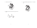
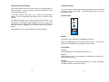
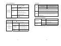
for
Thermal Receipt Printer
TM200 USER’S MANUAL
User’s Manual
Table of Contents
Introduction
Introduction .................................................... ii
CHAPTER 1
Setting Up the Printer
Unpacking....................................................................... 1-1
Connecting Cable ........................................................... 1-2
Installing or Replacing the Paper Roll ............................ 1-5
Adjustments and Settings............................................... 1-8
Using the Printer ............................................................. 1-9
CHAPTER 2
Reference Information
Printing Specifications ................................................... 3-1
Paper Specifications...................................................... 3-3
Electrical Characteristics ............................................... 3-3
Environmental Conditions ............................................. 3-4
CHAPTER 4
The printers have the following features:
Printing
High-speed printing: 180 mm/sec, 60 lines /sec maximum.
The Self Test
The Self Test................................................................... 2-1
CHAPTER 3
TM200 series printers are high-quality POS printers, and design for use
with electronic instruments such as system ECR, POS, banking
equipment, computer peripheral equipments.
Low-noise thermal printing.
Application Software
®
Command protocol is based on the ESC / POS standard.
Various layouts are possible by using page mode.
Characters can be scaled up to 4 times as large as standard size.
Troubleshooting
General questions ......................................................... 4-1
Printing questions.......................................................... 4-1
Cleaning the print head ................................................. 4-3
Auto cutter questions .................................................... 4-4
Hexadecimal Dump............................................................... 4-6
Bar code printing is possible by using a bar code command. i.e. Bar
codes can be printed both in vertical direction, and in the horizontal
direction.
Repeated operations and copy printing are possible by using macro
APPENDIXES
Appendix A
DIP Switch and Paper Near End Settings..................... A-1
Appendix B
Connectors .................................................................... A-7
definitions.
Character font size (12 x 24 font or 9 x 17 font) can be selected
using a command.
MU04001D
i
ii
Printer Handling
Chapter 1. Setting Up the Printer
Easy drop-in paper roll loading
Unpacking
An auto-cutter is standard
The illustration below shows the items should included for the standard of
TM200 printer package. If any items are damaged or missing, please
contact with your dealer for assistance.
Support “partial” and “full” cutter.
Printer allows easy maintenance for tasks such as head cleaning
Three different print densities can be selected by DIP switches.
The built-in interface provides control capability for two drawers.
Interface: RS-232, Parallel Port, USB interface.
Paper roll
AC adapter
Power cord
Options and Accessories
TM200 power supply unit
Communication cable
RS-232 interface board
Parallel interface board
User’s manual
USB interface board
Printer
Standard cable cover set (included wall mounting bracket)
Top waterproof cover
Thermal paper reel
Communication cable
iii
Windows driver
1-1
Connecting the Cables
Connecting the drawer
You can connect up to three cables to the printer. They all connect to the
connector panel on the back of the printer, which is shown below:
WARNING:
Use a drawer that matches the printer specification. Using an
improper drawer may damage the drawer as well as the printer.
CAUTION:
Do not connect a telephone line to the drawer kick-out connector;
otherwise the printer and the telephone line may be damaged.
Plug the drawer cable into the drawer kick-out connector on the back of
the printer next to the power supply connector.
Interface
Drawer kick-out
Power supply
Power supply
Notes:
There is a caution label above the drawer kick-out connector.
Depending on the interface installed, the interface connector on your
printer may look different from the one illustrated.
Before connecting any of the cables, make sure that both the printer and
the computer are turned off.
Connecting the computer
You need an appropriate interface cable.
1.
2.
Plug the cable connector securely into the printer’s interface
connector.
If the printer has a serial interface, tighten the screws on both sides
of the cable connector.
If the printer has a parallel interface, squeeze the wire clip on the
printer together until they lock in place on both sides of the connector.
3.
Attach the other end of the cable to the computer.
1-2
1-3
Connecting the Power Supply
Installing or Replacing the Paper Roll
WARNING:
Notes:
Be sure to use paper rolls that meet the specifications. Do not use
paper rolls that have the paper glued to the core because the printer
cannot detect the paper end correctly.
Make sure that you use the optional +24V power supply or
equivalent for your printer. Using an incorrect power supply may
caused fire or electrical shock.
1.
Make sure that the printer is not receiving data; otherwise, data may
be lost.
2.
Open the paper roll cover by pressing the cover-open button. If
the cover-open button will not open the cover, see page 4-3 or 4-5
in Troubleshooting.
CAUTION:
When connecting or disconnecting the power supply from the printer,
make sure that the power supply is not plugged into an electrical
outlet. Otherwise you may damage the power supply or the printer.
If the power supply’s rated voltage and your outlet’s voltage do not
match, contact your dealer for assistance. Do not plug in the power
cord. Otherwise, you may damage the power supply or the printer.
1.
Make sure that the printer’s power switch is turned off, and the
power supply’s power cord is unplugged from the electrical
outlet.
2.
Check the label on the power supply to make sure that the
voltage required by the power supply matches that of your
electrical outlet.
3.
Plug in the power supply’s cable as shown below. Notice that
the flat side of the plug faces down.
Notes:
Do not open the print cover while the printer is operating. This may
damage the printer.
3.
Remove the used paper roll core if there is one.
Notes:
To remove the DC cable connector, make sure that the power supply’s
power cord is unplugged; then grasp the connector at the arrow and pull
it straight out.
1-4
1-5
4.
Insert the paper roll as shown.
6.
Pull out a small amount of paper, as shown. Then close the
cover.
5.
Be sure to note the correct direction that the paper comes off
the roll.
1-6
1-7
Adjustments and Settings
Using the Printer
The TM200 Series are set up at the factory to be appropriate for
almost all users. It does, however, offer some settings for users
with special requirements.
You can control the basic paper feeding operations of the printer with
the button on the control panel. The indicator lights help you monitor
the printer’s status.
It has DIP switches that allow you to change communication
settings, such as handshaking and parity check, as well as print
density.
Control Panel
The TM200 Series also have a near-end sensor for the paper. This
can give you a warning when the paper is almost out. If you find
that there is not enough paper remaining on the roll when the
near-end detector is triggered, you can change the near-end sensor
setting.
POWER
See Appendix A if you need to make any of these changes.
FEED
ERROR
PAPER
Button
The button can be disabled by the ESC c 5 command.
Press the FEED button once to advance paper one line. You can also
hold down the FEED button to feed paper continuously.
Panel lights
POWER
The POWER light is on whenever the printer is on.
ERROR
This indicates an error. See Chapter 4 for information on what to do
when this light comes on.
PAPPER
This light indicates the near end of the paper roll. Install a new paper
roll and the printer will continue printing.
1-8
1-9
Indicator on Control Panel
POWER
ERROR
Chapter 2. The self test
The self test lets you know if your printer is operating properly. It checks
the control circuits, printer mechanisms, print quality, ROM version, and
DIP switch settings.
Status
Description
Power light “On”
Printer power is on.
Power light “Off”
Power cable is not connected with
printer
Status
Description
Running the self test
ERROR light is “On”
(not blinking), and
heard beeper sound
Turn off the printer and check if
cutter was seized.
1. Make sure the printer is turned off and the printer covers are closed
properly.
This test is independent of any other equipment or software.
PAPER
FEED
ERROR light is
”Blinking“
2. Make sure a paper roll has been installed properly.
Make sure that the printer cover is
properly closed. Press the printer
cover audibly clicks into place.
ERROR light is Off,
but noting is printed
Try to run the self test to check that
the printer works properly. See the
self test instructions in Chapter 1.
Status
Description
PAPER light is “On“
There is a paper roll inside the
printer.
PAPER “Red” light is
“On”
The paper roll is near end.
PAPER “Red” light is
“Blinking“
The paper roll is not installed or is
at the end. Install a new paper
roll. See Chapter 1 for
instructions.
PAPER light is “Off“
If power is connected, and PAPER
light still Off, please turn off power,
and check if printer on
programming mode.
1-10
3. While holding down the FEED button, turn on the printer using the
switch on the front of the printer to begin the self test. The self test prints
the printer settings, and then prints the following, cuts the paper, and
pauses.
If you want to continue SELF-TEST
Please press the FEED button
4. Press the FEED button to continue printing.
pattern using the built-in character set.
The printer prints a
5. The self test automatically ends and cuts the paper after printing the
following.
***
completed
***
Please re-start to exit SELF-TEST
2-1
Chapter 3. Reference Information
Standard
Printing Specifications
Printing method:
Thermal line printing
Dot density:
203 dpi x 203 dpi (8 dot/mm)
W x H (mm)
Font A
1.23 x 2.97
Printing direction:
Unidirectional with friction feed
12 x 24
(.05” x .11”)
Printing width:
72mm (2.83”), 576 dot positions
Font B
0.87 x 2.10
Characters per line
48 (Font A)
9 x 17
(.035” x .08”)
(default):
64 (Font B)
Kanji
2.97 x 2.97
24 x 24
(.11” x .11”)
Character spacing (default): 0.28 mm (0.1”) (2 dots) (Font A)
0.28mm
Double-height
CPL
W x H (mm)
1.23 x 5.92
48
64
(.05” x .24”)
0.87 x 4.20
(.035” x .17”)
2.97 x 5.92
24
(.11” x .24”)
CPL
48
64
24
(.01”) (2 dots) (Font B) Programmable by
control command.
Printing speed -High-speed mode:
Paper feeding speed:
180 mm / sec (approxi. 7.0” / sec)
60 lines / sec (computed value for 3.18mm
(1/8”) feed)
28.4 lines / sec maximum
(4.23 mm (1/6”) feed, at 24V, 28。C (82。F),
density level 2)
Approximately 180 mm / sec (7.0”/sec)
continuous paper feeding
Receive Buffer Size
80K Bytes
Number of characters:
Alphanumeric characters: 95
International characters: 32
Extended graphics: 128x7pages
(including one space page)
Traditional/ Simplified Chinese, Japanese,
Kanji characters
Character structure:
Font A: 12 x 24 (including 2-dot
spacing horizontally)
Font B: 9 x 17 (including 2-dot spacing
horizontally)
Kanji: 24 x 24
Default font: Font A
3-1
Double-width
W x H (mm)
Font A
2.47 x 2.97
12 x 24
(.10” x .11”)
Font B
1.73 x 2.10
9 x 17
(.07” x .08”)
Kanji
5.92 x 2.97
24 x 24
(.24” x .11”)
Double-weight/ Double-height
CPL
W x H (mm)
2.47 x5.92
24
(.10” x .24)
1.73 x 4.20
32
(.07” x .17”)
5.92 x 5.92
12
(.24” x .24”)
CPL
24
32
12
* CPL = Characters Per Line
* Space between characters is not included
* Characters can be scaled up to 64 times as large as the standard sizes.
3-2
Paper Specifications
Reliability
Size:
Width: 80.0mm+0.5mm
(3.15” + 0.02”)
Life:
Maximum outside
83 mm (3.27”)
diameter:
Paper roll
(single-ply):
Paper roll spool
Inside: 12mm (0.47”)
diameter:
Outside: 18mm (0.71”)
Paper must not be pasted to
15,000,000 lines
Thermal head:
100 million pulses, 50 km
Auto cutter:
1,200,000 cuts
(End of Life is defined to have reached the end of its
life when it reaches the beginning of the Wear out Period.)
52,000,000 lines
MCBF:
(This is an average failure interval based on failures
the paper roll spool.
relating to wear out and random failures up to the life of
Take up paper roll
80 + 0.5 mm
15 million lines.)
width:
(3.15”+0.02”)
Environmental Conditions
Electrical Characteristics
Temperature:
+24 VDC + 7%
Supply voltage:
Current
consumption:
Operating:
5℃ to 45℃ (41℉ to 113 ℉)
Storage:
-10℃to 50℃ (14℉ to 122 ℉),
except for paper
(standard accessory power supply)
High-speed mode:
(at 24V)
Mechanism:
Low-power-
Mean: Approximately 1.7A
Peak: Approximately 7.7A
Humidity:
Operating:
10 to 90 % (RH)
Storage:
10 to 90 % RH, except for paper
Mean: Approximately 1.2A
consumption
Peak: Approximately 6.6A
mode:
Standby
Mean: Approximately 0.2A
3-3
3-4
Chapter 4. Troubleshooting
If the self test works properly, check the following:
Make sure that the power supply cables are correctly plugged into the
printer, the power unit, and to the power outlet.
1. Check the connection at both ends of the interface cable
between the printer and the computer. Also make sure that this
cable meets the specifications for both the printer and the
computer.
2. The data transmission settings may be different between the
printer and computer. Make sure that the printer’s DIP switch
settings for data transmission are the same as the computer.
You can print the printer’s interface settings using the self test.
Make sure that power is supplied to the power outlet. If the outlet is
controlled by a switch or timer, use another outlet.
If the printer still does not print, contact your dealer or a qualified
service person.
Printing questions
※Printing is poor.
※The ERROR light is on (not blinking), and heard beeper sound but
nothing is printed.
Paper dust on the heating element of the thermal print head can
lower the print quality. Try cleaning the print head as described
below:
This chapter gives solutions to some printer questions you may have.
General questions
※The lights on the control panel do not come on.
First, turn off the printer and check if cutter was seized.
If there is no cutter seized and the print head is not overheated, turn
off the printer and turn it back on after about 10 seconds.
※The ERROR light is blinking.
Make sure that the printer cover is properly closed. Press the printer
cover audibly clicks into place.
If the ERROR light is still flashing, contact a qualified service person.
※If the PAPER “Red” light is On.
The paper roll is at or near the end. Install a new paper roll. See
Chapter 1 for instructions.
※If the PAPER “Red” light is blinking.
The paper roll is not installed or is at or near the end. Install a new
paper roll. See Chapter 1 for instructions.
※Buzzers make beep sound.
Normal buzzers beep sound:
The buzzers can indicate the printer is completed print. It will beep
sound after printer cut the paper to indicate the printing is finished.
Abnormal buzzers beep sound:
Cutter seized will make the buzzers beep sound. For this status, turn off
the printer and check if cutter was seized.
If the printer not installed with interface board, it will make the buzzers
beep sound. To make sure that the interface board is properly installed.
Note:
You may disable the buzzers function by changing DIP switch
settings, “SW3” of pin 1, and 2 setting to “ON”.
※The ERROR light is Off, but nothing is printed.
Try to run the self test to check that the printer works properly. See
the self test instructions in Chapter 1 to run the self test. If the self
test does not work, contact your dealer or a qualified service person.
4-1
4-2
Cleaning the print head
CAUTION:
After printing, the print head can be very hot. Be careful not to touch it.
Also let it cool before you clean it. Do not damage the print head by
touching it with your fingers or any hard object.
4. Then turn the knob until you see cutter blade back to the lowest
position, as shown in the illustration below. This returns the
cutter blade to the normal position. Also notice that there is a
label near the cutter to assist you.
When paper
jams, turn the
knob until the
cutter blade back
to lower position.
1.
Open the printer cover.
2.
Clean the thermal element of the print head with a cotton swab
moistened with alcohol solvent (ethanol, methanol, or IPA).
Radiation plate
Head
Thermal element
5.
Close the cutter cover.
6.
Open the printer cover.
7.
Remove the jammed paper.
Paper handling questions
※ Paper is jammed inside the printer.
Auto cutter questions
※ The auto cutter is jammed.
CAUTION:
Do not touch the print head because it can be very hot after printing
continuously for a long time.
To clear a paper jam, follow the steps below:
1. Turn the printer off and press the cover open button to open the
cover.
2. Remove the jammed paper and put the roll back in the printer
and close the cover. (Take care not to touch the print head.)
3. If paper is caught in the automatic cutter and the printer cover
cannot be opened, open the cutter cover as shown below.
4-3
If a foreign object such as a push pin or paper clip drops in the
auto cutter and causes the auto cutter to lock up, the printer enters
an error state and begins the recovery operation automatically.
If the problem is not serious, the auto cutter returns to its normal
position without any intervention by the user.
If the auto cutter does not return to its normal position by itself, follow
the steps below to correct the problem:
4-4
1.
Pull the cutter cover toward you so that you can rotate the
cutter motor knob.
Hexadecimal Dump
This feature allows experienced users to see exactly what data is
coming to the printer. This can be useful in finding software
problems. When you turn on the hex dump function, the printer
prints all commands and other data in hexadecimal format along
with a guide section to help you find specific commands.
To use the hex dump feature, follow these steps:
2.
Following the instructions on the label, rotate the knob until
the cutter blade draw back to normal position.
1.
After you make sure that the printer is off, open the cover.
2.
Hold down the FEED button while you turn on the printer.
3.
Close the cover.
4.
Run any software program that sends data to the printer.
The printer prints “Hexadecimal Dump” and then all the
codes it receives in a two-column format. The first column
contains the hexadecimal codes and the second column
gives the ASCII characters that correspond to the codes.
When paper
jams, turn the
knob until the
cutter blade back
to lower position.
Hexadecimal Dump
1B 21 00 1B 26 02 40 40 ← ! ← & ☻ @ @
1B 25 01 1B 63 34 00 1B ←%☺← c 4
←
41 42 43 44 45 43 47 48 ABCDEFGH
5.
Close the cover and turn off the printer or reset it to turn off
the hex dump mode. (or to terminate hex dump, press FEED
button three times, and when you see
*** completed ***, the hex dump mode was turned off.
3.
Close the cutter cover.
NOTE:
In case if you need disable auto cutter, just setting the DIP switch,
SW1 of “1-5” pin to “ON”, and printer can use tear-bar for paper tear off.
4-5
4-6
APPENDIXES
Set 2
SW
Function
2-1
APPENDIX A
Data receive error
Receive buffer
capacity
Handshaking
Data word length
Parity check
Parity selection
2-2
Dip Switch and Paper Near End Settings
Although the factory settings are best for almost all uses, if you have
special requirements, you can change the DIP switch or paper near
end settings.
Setting the DIP Switches
DIP switch functions
Set 1
SW
Function
ON
OFF
1-1
1-2
1-3
1-4
1-5
1-6
1-7
Print emulation
Paper near end sensor
TM200
Vertical
EPSON Emulation
Horizontal
1-8
80K bytes
2K bytes
XON / XOFF
7 bits
Enabled
Even
DTR / DSR
8 bits
Disabled
Odd
Transmission speed (See the table below)
Transmission Speed
(BPS) –bits per second
4800
9600
19200
38400
Serial interface specification
Cutter setting
Stop bit
Cutter mode
Reserved: do not
change settings
OFF
Prints “?”
Transmission Speed
Your printer has three sets of DIP switches. The functions of the
switches are shown in the following tables.
Selects print density
2-3
2-4
2-5
2-6
2-7
2-8
ON
Ignored
Refer to page ‘A-3” table
Disable
2 bits
Full
Enable
1 bit
Partial
2-7
2-8
OFF
ON
OFF
ON
ON
OFF
OFF
ON
Set 3
SW
Function
ON
OFF
3-1
3-2
3-3 ~ 3-8
Buzzer1 setting
Buzzer 2 setting
Undefined
Disable
Disable
-
Enable
Enable
-
Fixed to OFF
Dip Switch and Paper Near End Settings A–1
Dip Switch and Paper Near End Settings A-2
Print Density Selection
Print Density
Parallel interface specification
SW 1-3
SW 1-4
1 Low power consumption mode
ON
ON
2 (Normal)
OFF
OFF
3
ON
OFF
4 (Dark)
OFF
ON
Notes:
If the DIP switch setting is changed after the printer power is
turned on, the change does not take effect until the printer is
turned on again or is reset.
DIP switches should not be changed while the printer power is
on.
Set 1
SW
Function
ON
OFF
1-1
1-2
1-3
1-4
1-5
1-6
1-7
Print emulation
Paper near end sensor
TM200
Vertical
EPSON Emulation
Horizontal
1-8
Selects print density
Cutter setting
Parallel port supports
Cutter mode
Reserved: do not
change settings
Refer to page “A-5” table
Disable
EPP
Full
Enable
SPP/EPP
Partial
Fixed to OFF
Set 2
SW
Function
ON
OFF
2-1
Auto line feed
Receive buffer
capacity
Undefined
Always enabled
Always disabled
2K bytes
80K bytes
-
-
2-2
2-3 ~ 2-8
Set 3
DIP Switch and Paper Near End Settings A–3
SW
Function
ON
OFF
3-1
3-2
Buzzer1 setting
Buzzer 2 setting
Disable
Disable
Enable
Enable
3-3 ~ 3-8
Undefined
-
-
Dip Switch and Paper Near End Settings A-4
Print Density Selection
Print Density
Changing the DIP switch settings
SW 1-3
SW 1-4
1 Low power consumption mode
ON
ON
2 (Normal)
OFF
OFF
3
ON
OFF
4 (Dark)
OFF
ON
Notes:
If the DIP switch setting is changed after the printer power is
turned on, the changed does not take effect until the printer is
turned on again or is reset.
If you need to change settings, follow the steps below to make your
changes:
CAUTION:
Turn off the printer while removing the DIP switch cover to prevent an
electric short, which can damage the printer.
1.
Make sure the printer is turned off.
2.
Remove the screw from the DIP switch cover. Then take off the
DIP switch cover, as sown in the illustration below.
DIP switches should not be changed while the printer power is on.
SW3
SW2
SW1
3.
Set the switches using a pointed tool, such as tweezers or a small
screwdriver.
4.
Replace the DIP switch cover. Then secure it with the screw.
The new settings take effect when you turn on the printer.
DIP Switch and Paper Near End Settings A–5
Dip Switch and Paper Near End Settings A-6
APPENDIX B
Parallel Interface (IEEE-1284)
Connectors
Interface connector
Drawer kick-out
connector
Power supply
connector
TM200 Connector (Serial interface)
Interface connector
Drawer kick-out
Power supply
connector
connector
TM200 Connector (Parallel Interface)
Pin No.
Source
1
2
3
4
5
6
7
8
9
10
11
Host
Host / Printer
Host / Printer
Host / Printer
Host / Printer
Host / Printer
Host / Printer
Host / Printer
Host / Printer
Printer
Printer
Compatibility
mode
nStrobe
Data 0 (LSB)
Data 1
Data 2
Data 3
Data 4
Data 5
Data 6
Data 7 (MSB)
nAck
Busy
12
Printer
Perror
13
14
15
16
17
18
19~30
31
Printer
Host
Host
Select
nAutoFd
NC
GND
FG
Logic-H
GND
nInit
32
Printer
nFault
33
34
35
36
Printer
Printer
Host
GND
DK_Status
+ 5V
nSelectIn
Printer
Nibble Mode
HostClk
HostClk
Data 0(LSB)
Data 1
Data 2
Data 3
Data 4
Data 5
Data 6
Data 7 (MSB)
PtrClk
PtrClk
PtrBusy /Data3,7
PtrBusy
AckDataReq/
AckDataReq
Data2,6
Xflag /Data1,5
Xflag
HostBusy
HostBusy
NC
NC
GND
GND
FG
FG
Logic-H
Logic-H
GND
GND
nInit
nInit
nDataAvail/
nDataAvail
Data0,4
ND
ND
ND
ND
ND
ND
1284-Active
1284-Active
Drawer Connector
Interface Connector
Serial Interface (RS-232)
Pin No.
Signal name
Direction
Function
1
2
3
6
7
20
FG
RxD
TxD
DTR
SG
DSR
Input
Output
Output
Input
Frame Ground
Receive Data
Transmit Data
Data Terminal Ready
Signal Ground
Data Set Ready
A–7
Pin No.
1
2
3
4
5
6
Signal name
Frame ground
Drawer kick-out drive signal 1
Drawer open/close signal
+24V
Drawer kick-out drive signal 2
Signal ground
A-8
Byte Mode
Direction
Output
Input
Output
-