1
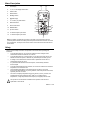
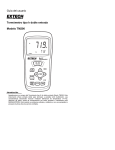
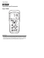
User Guide
Type K Dual Input Thermometer
Model TM200
Introduction
Congratulations on your purchase of the Extech TM200 Type K Dual Input Thermometer.
This instrument offers a dual thermocouple input and a multifunction LCD display.
Additional features include differential temperature measurement (T1-T2), Data Hold,
push-button Offset adjustment, and MIN/MAX/AVG displays. This meter is shipped fully
tested and calibrated and, with proper use, will provide years of reliable service.
Meter Description
12
1.
LCD display
2.
T1, T2, T1-T2 display select button
3.
Power button
4.
SETUP button
5.
Backlight button
6.
Min/Max button
7.
o
8.
Data Hold button
9.
Down arrow button
o
13
1
o
C F Kelvin ( K) select button
2
10. ENTER button
11. Up arrow button
12. T2 Thermocouple input socket
3
4
5
11
10
9
6
8
13. T1 Thermocouple input socket
7
Note: The battery compartment is located on the back of the instrument under the
protective jacket. Remove the rubber protective jacket that encases the meter to access
the compartment. The tripod mount access is also on the back of the instrument above
the tilt stand.
Safety
Please read the safety information and operation instructions before operating this
instrument.
•
To avoid electrical shock, do not use this instrument when voltages at the
measurement surface exceed 24V ac or 60V dc.
•
To avoid electrical shock or personal injury, do not apply more than 20V ac rms,
between the thermocouples, or between any thermocouple and earth ground.
•
If voltage on the measurement surface results in potentials of more than 1V,
measurement errors may occur.
•
If a potential exists between the thermocouples, use electrically insulated
thermocouples
•
To avoid meter damage and burn hazards, do not use this instrument to measure
temperature in a microwave oven.
•
Avoid repeated sharp flexing of the thermocouple wire as this can cause
thermocouple lead breakage. To prolong lead life, avoid sharp bends in the leads,
especially near the connector.
o
o
•
The meter can display temperature as high as 2501 F (1372 C), however, the
o
o
supplied thermocouple is rated for 500 F (260 C). To measure higher
temperatures, a high-temperature thermocouple (not supplied) must be used.
!
This symbol on the instrument indicates that the operator must refer to an
explanation in this manual.
2
TM200 V4.1 11/06
Operation
Connecting thermocouples
1.
This meter accepts one or two thermocouples. Only type K thermocouples with spade
plugs (sub-miniature type with one spade wider than the other) may be used.
2.
Plug one thermocouple into the meter's T1 input jack and optionally plug another
thermocouple into the meter’s T2 input jack.
Turn Power ON
1. Press the
button to turn the meter on.
2. If a probe is not inserted to the meter, dashes “-----” will appear on the display.
o
o
o
Selecting C / F / Kelvin ( K) unit of measure
o
o
Use the C / F / K button to select the desired unit of measure.
Taking Measurements
Hold the thermocouple in air or touch the tip of the thermocouple to a device under test
and read the temperature on the meter’s LCD. If the measured temperature exceeds the
meters high or low limits, ‘OL’ will appear in place of a temperature reading.
o
o
Important Note: The supplied thermocouples are rated for 500 F (260 C). To measure
higher temperatures, a high-temperature Type K thermocouple (not supplied) must be
used.
Display resolution
o
o
o
The meter has a 0.1 resolution on displays ranging from 0.1 to 999.9 . The resolution is
o
o
1 for temperatures 1000 and higher.
Selecting T1, T2, and T1-T2 Displays
Use the T1, T2, T1-T2 button to select the desired display configuration
•
When the meter is turned on, the T1 thermocouple reading is displayed on the
primary display and the T2 reading is displayed on the secondary (smaller display).
•
First press of the button: The T1 and T2 displays switch places (the T2 reading is now
on the primary display and the T1 reading is on the secondary display)
•
Second press: The differential (T1-T2) is shown on the primary display and the T1
temperature reading is shown on the secondary display.
•
Third press: The differential value (T1-T2) is shown on the primary display and the T2
temperature reading is shown on the secondary display.
•
Fourth press: The display configuration loops back to the start up condition (the T1
reading is displayed on the primary and the T2 reading is displayed on the secondary)
Backlight
Press the
backlight button to switch on the LCD display backlight. Press the button
again to turn the backlight off. Judicious use of the backlight feature will conserve battery
power.
Data Hold
Press the HOLD button to freeze the readings in the display. The 'HOLD' icon will appear
above the temperature reading on the display. Press the HOLD button again to return to
normal operation (the 'HOLD' hold icon will disappear).
Tripod Mount
The tripod mounting connector is located on the back of the meter. Tripods are available
through Extech Instruments distributors.
3
TM200 V4.1 11/06
MIN / MAX /AVG Display Function
In the MIN MAX mode the meter tracks the lowest (MIN), highest (MAX), and average
(AVG) readings while displaying elapsed time.
1. Press the MIN MAX button to start the Elapsed Timer (bottom left side of LCD)
2. Begin taking measurements
3. The secondary display (lower right) will display only the primary display’s highest
reading (the MAX icon will be visible on the bottom of the LCD).
4. Press the MIN MAX button to see the MIN (minimum) reading.
5. The secondary display (lower right) will display only the primary display’s lowest
reading (the MIN icon will be visible on the bottom of the LCD).
6. Press the MIN MAX button to see the AVG (reading)
7. The secondary display (lower right) will display only the primary display’s average
reading (the AVG icon will be visible on the bottom of the LCD).
8. Press and hold the MIN MAX button for three (3) seconds to exit this mode and return
to normal operation (the MIN, MAX, and AVG display icons should switch off when
this mode is successfully exited).
9. Note that in MIN MAX mode, the T1 T2 / T1-T2 button is active allowing the user to
view the MIN/MAX/AVG of the T1, T2, or T1-T2 displays.
Auto Power OFF (Sleep Mode)
The meter will automatically turn off if no keys are pressed during any twenty (20) minute
period. To configure the Sleep Mode ON or OFF:
1. With the meter ON, press the SETUP button to enter the SETUP mode (the SETUP
display icon will appear on the LCD)
2. Repeatedly press the UP arrow button until the SLP (sleep) icon appears on the LCD
3. Press the ENTER button (on or off will appear on the LCD under the SLP icon)
4. Use the UP/DOWN arrow buttons to select ON (sleep mode on) or OFF (sleep mode
defeated)
5. Press ENTER again to save the selection
6. Press SETUP again to exit the setup mode and to return to normal operation.
Display OFFSET adjustment
Use the display OFFSET feature to compensate for thermocouple irregularities and to
o
o
better match two thermocouples. The allowable offset range is ± 9 F (±5 C).
1. With the meter ON, press the SETUP button to enter the SETUP mode (the SETUP
display icon will appear on the LCD)
2. Use the UP arrow button to select input T1 or input T2 (icons are shown on left side
of LCD)
3. Press the ENTER button; the temperature reading will appear in the primary display
area. The offset will be shown in the smaller secondary display area
o
4. Use the UP/DOWN arrow buttons to program an offset. The available range is ± 9 F
o
(±5 C)
5. Press ENTER again to save the selection
6. Press SETUP again to exit the setup mode and to return to normal operation.
Turning Power OFF
Press the
button to turn power off.
4
TM200 V4.1 11/06
Maintenance
Battery Replacement
When the low battery symbol
appears on the display, replace the 9V battery:
1.
Remove the rubber protective jacket that encases the meter. If this jacket is not
removed, the battery compartment cannot be accessed.
2.
Remove the rear Phillips screw that secures the battery compartment.
3.
Open the compartment and replace the 9V battery.
4.
Secure the meter’s battery compartment and rubber jacket before using the meter.
WARNING! To avoid electrical shock, disconnect the thermocouples before removing the
battery cover.
Cleaning
Use a damp cloth with a mild detergent to periodically wipe the meter housing and display
area. Do not use abrasives or solvents to clean the meter.
5
TM200 V4.1 11/06
Specifications
Measurement Range
°
°
-328 to 2501 F (-200 to 1372 C)*
°
°
°
°
°
o
Max. Resolution
0.1 C/ F<999.9 , 1 C/ F>1000
Accuracy (T1&T2)
-148 to 2501 F (-100 to 1372 C) ± [0.5% of reading + 1.8 F(1 C)]
°
°
o
°
°
°
o
°
-328 to -148 F (-200 to -100 C)
Temperature
Coefficient
± [0.5% of reading + 3.6 F(2 C)]
°
°
0.1 times the applicable accuracy specifications per C from 0 C to
°
°
°
°
°
°
°
18 C and 28 C to 50 C (32 F to 64 F and 82 F to 122 F)
Note: Temperature accuracy does not include the accuracy of the type K probe
o
Note: Temperature accuracy specifies @ 23 ± 5 C
Note: The temperature scale is based on the international temperature scale of 1990
(ITS90)
°
°
Note: Supplied thermocouples rated for 500 F (260 C) max.
General Specifications
Display
Multi-function LCD with Backlight
Input Protection
60VDC; 24VAC rms
Display Update Rate
2.5 times per second
Over range indication
"OL" appears on the LCD
Open input indication
Dashes "-------" appears on the LCD
Low battery indication
“
Power supply
9V alkaline battery
Auto Power OFF
After 20 minutes of inactivity (programmable)
” appears on the LCD
o
o
Ambient Operating conditions 4 to 122 F (0 to 50 C) / < 80% Relative Humidity
o
o
Ambient Storage conditions
14 to 122 F (-10 to 50 C) / 10 to 80% Relative Humidity
Dimensions
6.5 x 3.0 x 1.7" (165 x 76 x 43mm) without holster
Weight
7.4oz (210g) with battery
6
TM200 V4.1 11/06
Warranty
EXTECH INSTRUMENTS CORPORATION warrants this instrument to be free of defects in parts and workmanship for one
year from date of shipment (a six month limited warranty applies on sensors and cables). If it should become necessary to
return the instrument for service during or beyond the warranty period, contact the Customer Service Department at (781)
890-7440 ext. 210 for authorization or visit our website at www.extech.com (click on ‘Contact Extech’ and go to ‘Service
Department’ to request an RA number). A Return Authorization (RA) number must be issued before any product is returned
to Extech. The sender is responsible for shipping charges, freight, insurance and proper packaging to prevent damage in
transit. This warranty does not apply to defects resulting from action of the user such as misuse, improper wiring, operation
outside of specification, improper maintenance or repair, or unauthorized modification. Extech specifically disclaims any
implied warranties or merchantability or fitness for a specific purpose and will not be liable for any direct, indirect, incidental
or consequential damages. Extech's total liability is limited to repair or replacement of the product. The warranty set forth
above is inclusive and no other warranty, whether written or oral, is expressed or implied.
Calibration and Repair Services
Extech offers complete repair and calibration services for all of the products we sell.
For periodic calibration, NIST certification or repair of this Extech product, call customer
service for details on services available. Extech recommends that calibration be performed
on an annual basis to ensure calibration integrity.
Support line (781) 890-7440
Technical support: Extension 200; E-mail: [email protected]
Repair & Returns: Extension 210; E-mail: [email protected]
Product specifications subject to change without notice
For the latest version of this User Guide, Software updates, and other
up-to-the-minute product information, visit our website: www.extech.com
Extech Instruments Corporation, 285 Bear Hill Road, Waltham, MA 02451
Copyright © 2006 Extech Instruments Corporation.
All rights reserved including the right of reproduction in whole or in part in any form.
7
TM200 V4.1 11/06