1
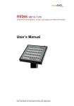
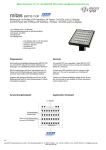
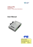
mitas BBT32-T
Control Panel with 34 Buttons, 34 LEDs, LCD Display and serial Interface
User’s Manual
microSYST Systemelectronic GmbH, Albert-Einstein-Straße 7, 92637 Weiden, Germany
Phone: +49 961 39166-0, Fax: +49 961 39166-10, www.microsyst.de, [email protected]
mitas BBT32-T
Control Panel with 34 Buttons, 34 LEDs, LC-Display and serial Interface
Table of Contents
1
GENERAL
3
2
TECHNICAL INFORMATION
4
3
4
5
2.1
Serial Communication
2.1.1 LED / Button Assignment
2.1.2 LCD Display
2.1.3 SD Card
2.1.4 CSV File
2.1.5 Starting Procedure
2.1.6 Control Frame
2.1.7 Response Frame
5
5
6
6
6
6
7
8
2.2
9
Examples
CONNECTOR PIN ASSIGNMENTS / SETTINGS
10
3.1
Connectors
10
3.2
Switches
12
3.3
Status-LEDs
13
MOUNTING OPTIONS
14
4.1
Panel Mounting
14
4.2
Housing
15
4.3
Pedestal
16
APPENDIX
17
5.1
Maintenance and Care
17
5.2
Warranty / Liability
18
5.3
Versions Overview
19
Page 2
microSYST Systemelectronic GmbH, Albert-Einstein-Straße 7, 92637 Weiden, Germany
Phone: +49 961 39166-0, Fax: +49 961 39166-10, www.microsyst.de, [email protected]
mitas BBT32-T
Control Panel with 34 Buttons, 34 LEDs, LC-Display and serial Interface
1 General
The “mitas BBT32-T” control panel reduces previous wiring and installation
efforts to a minimum.
34 buttons with LED indication form the concept of the basic unit. This unit
is operated via a serial interface RS422 or RS485.
Fault or information messages can be displayed on the integrated LC display. The messages are stored in a CSV file on a SD card.
Additionally, 3 digital inputs and 3 digital outputs are available (e.g. to connect a key switch).
Page 3
microSYST Systemelectronic GmbH, Albert-Einstein-Straße 7, 92637 Weiden, Germany
Phone: +49 961 39166-0, Fax: +49 961 39166-10, www.microsyst.de, [email protected]
mitas BBT32-T
Control Panel with 34 Buttons, 34 LEDs, LC-Display and serial Interface
2 Technical Information
General Specifications
Interface:
Baud rate:
Addresses:
Keys/LEDs:
Display:
Digital inputs:
Digital outputs:
Text memory:
Labelling:
Operating voltage:
Power consumption:
Mounting:
Protection:
Housing:
Housing dimensions:
Operating temperature:
Storage temperature:
RS485, RS422
2.4 to 115.2 kBaud, adjustable
0 to 99
8 x 4 + 2 + 2 Taster,
8 x 4 + 2 + 2 LEDs + 4 LEDs for status display
(2x POWER, FAULT und DATA)
LCD, two lines with 24 characters each,
white LED backlight
quantity: 3 (24 VDC) with additional common 0V
connection
quantity: 3 (24 VDC, max. 200 mA per output)
1024 messages on a SD card (max. 2 GB);
1 message can extend up to 8 lines
labelling strips
24 VDC ±20%, protected against polarity reversal
approx. 150 mA at 24 VDC operating voltage
plus current for digital outputs (load dependent)
panel mounting
front panel IP65
without;
option:
- housing (powder coated sheet steel),
colour: RAL 7016 (anthracite)
- housing with pole (powder coated sheet steel),
colour: RAL 7016 (anthracite)
see chapter “Mounting Options”
0 to +50 °C
-25 to +60 °C
Page 4
microSYST Systemelectronic GmbH, Albert-Einstein-Straße 7, 92637 Weiden, Germany
Phone: +49 961 39166-0, Fax: +49 961 39166-10, www.microsyst.de, [email protected]
mitas BBT32-T
Control Panel with 34 Buttons, 34 LEDs, LC-Display and serial Interface
2.1 Serial Communication
All required interface parameters can be adjusted with the help of
switches (see chapter “Connector Pin Assignments”).
After a control frame from the Master (for controlling the LEDs or text
call at the LCD), the control panel replies with a response frame that
represents the states of the buttons.
3 digital inputs and 3 digital outputs can be controlled.
2.1.1 LED / Button Assignment
Page 5
microSYST Systemelectronic GmbH, Albert-Einstein-Straße 7, 92637 Weiden, Germany
Phone: +49 961 39166-0, Fax: +49 961 39166-10, www.microsyst.de, [email protected]
mitas BBT32-T
Control Panel with 34 Buttons, 34 LEDs, LC-Display and serial Interface
2.1.2 LCD Display
•
•
•
2 lines with 24 characters each
white backlight
2 buttons, “+” and “-“ for scrolling multiline messages
2.1.3 SD Card
•
•
•
•
Type: commercial cards up to 2 GB
Formatting: FAT
1024 messages storable
A message can have up to 8 lines with 24 characters each
2.1.4 CSV File
Messages can be created in an Excel table.
The file name must be “Texte.csv”.
The first column contains the message number (0 to 1023).
The second column contains the first line of the message (24 characters max.).
The third column contains the second line of the message (24 characters max.).
:
:
The ninth column contains the eighth line of the message (24 characters max.).
Lines without message number in the first column are not evaluated. So, even
headlines are possible. The message number must be ascending.
Example:
Alert
Line 1
Line 2
Line 3
Line 4
Line 5
Line 6
Line 7
Line 8
0
Text1, Line1 Text1, Line2 Text1, Line3 Text1, Line4 Text1, Line5 Text1, Line6 Text1, Line7 Text1, Line8
1
Text2, Line1 Text2, Line2 Text2, Line3 Text2, Line4 Text2, Line5 Text2, Line6 Text2, Line7 Text2, Line8
2
Text3, Line1 Text3, Line2 Text3, Line3 Text3, Line4 Text3, Line5 Text3, Line6 Text3, Line7 Text3, Line8
3
Text4, Line1 Text4, Line2 Text4, Line3 Text4, Line4 Text4, Line5 Text4, Line6 Text4, Line7 Text4, Line8
Error
Line 1
Line 2
Line 3
Line 4
Line 5
Line 6
Line 7
Line 8
4
Text5, Line1 Text5, Line2 Text5, Line3 Text5, Line4 Text5, Line5 Text5, Line6 Text5, Line7 Text5, Line8
5
Text6, Line1 Text6, Line2 Text6, Line3 Text6, Line4 Text6, Line5 Text6, Line6 Text6, Line7 Text6, Line8
2.1.5 Starting Procedure
The display shows a starting message with the version number and the interface parameters.
Page 6
microSYST Systemelectronic GmbH, Albert-Einstein-Straße 7, 92637 Weiden, Germany
Phone: +49 961 39166-0, Fax: +49 961 39166-10, www.microsyst.de, [email protected]
mitas BBT32-T
Control Panel with 34 Buttons, 34 LEDs, LC-Display and serial Interface
2.1.6 Control Frame
Frame Structure:
ADR
D1
D2
D3
D4
D5
D6 CHK
Address of the Data bytes according to the following Checksum:
BBT32
table
XOR combination of all 7 bytes
(ADR XOR D1 XOR D2 XOR D3
XOR D4 XOR D5 XOR D6)
Bit 7
Bit 6
Bit 5
Bit 4
Bit 3
Bit 2
Bit 1
Bit 0
D1
LED 8
LED 7
LED 6
LED 5
LED 4
LED 3
LED 2
LED 1
D2
LED 16
LED 15
LED 14
LED 13
LED 12
LED 11
LED 10
LED 9
D3
LED 24
LED 23
LED 22
LED 21
LED 20
LED 19
LED 18
LED 17
D4
LED 32
LED 31
LED 30
LED 29
LED 28
LED 27
LED 26
LED 25
Message
Bit 9
Message
Bit 7
Message
Bit 8
Message
Bit 6
Display ON
Output 3
Output 2
Output 1
LED 34
LED 33
Message
Bit 5
Message
Bit 4
Message
Bit 3
Message
Bit 2
Message
Bit 1
Message
Bit 0
D5
D6
LED
A LED lights, if it’s corresponding bit is set.
Message
A message is called with a number (10 bits).
Display ON
The display is switched-on, if the bit is set.
Output
An output is set with its corresponding bit.
Page 7
microSYST Systemelectronic GmbH, Albert-Einstein-Straße 7, 92637 Weiden, Germany
Phone: +49 961 39166-0, Fax: +49 961 39166-10, www.microsyst.de, [email protected]
mitas BBT32-T
Control Panel with 34 Buttons, 34 LEDs, LC-Display and serial Interface
2.1.7 Response Frame
After every control frame, the BBT32 replies with a response frame.
Frame Structure:
ADR
A1
A2
A3
A4
A5
A6
Address of the Response bytes according to the
BBT32
following table
CHK
Checksum:
XOR combination of all 7 bytes
(ADR XOR D1 XOR D2 XOR D3
XOR D4 XOR D5 XOR D6)
Bit 7
Bit 6
Bit 5
Bit 4
Bit 3
Bit 2
Bit 1
Bit 0
A1
Button 8
Button 7
Button 6
Button 5
Button 4
Button 3
Button 2
Button 1
A2
Button 16
Button 15
Button 14
Button 13
Button 12
Button 11
Button 10
Button 9
A3
Button 24
Button 23
Button 22
Button 21
Button 20
Button 19
Button 18
Button 17
A4
Button 32
Button 31
Button 30
Button 29
Button 28
Button 27
Button 26
Button 25
Message
Bit 9
Message
Bit 7
Message
Bit 8
Message
Bit 6
Display ON
Input 3
Input 2
Input 1
Button 34
Button 33
Message
Bit 5
Message
Bit 4
Message
Bit 3
Message
Bit 2
Message
Bit 1
Message
Bit 0
A5
A6
Button
If a button is pressed, its bit is set.
Message
Number of current displayed message (10 bits).
Display ON
The display is currently ON if this bit is set.
Input
A set bit means, the input is set.
Page 8
microSYST Systemelectronic GmbH, Albert-Einstein-Straße 7, 92637 Weiden, Germany
Phone: +49 961 39166-0, Fax: +49 961 39166-10, www.microsyst.de, [email protected]
mitas BBT32-T
Control Panel with 34 Buttons, 34 LEDs, LC-Display and serial Interface
2.2 Examples
All examples are valid for device address 1.
Switch-on LED 10:
01 00 02 00 00 00 00 03
Incoming response frame:
01 00 00 00 00 00 00 01
If button 4 is pressed during the controlling, you receive following response:
01 08 00 00 00 00 00 09
Switch display on and show message 20 (all LEDs are out):
01 00 00 00 00 20 14 35
Set output 1:
01 00 00 00 00 04 00 05
If input 3 is set at the same time, you receive the following response:
01 00 00 00 00 10 00 11
Page 9
microSYST Systemelectronic GmbH, Albert-Einstein-Straße 7, 92637 Weiden, Germany
Phone: +49 961 39166-0, Fax: +49 961 39166-10, www.microsyst.de, [email protected]
mitas BBT32-T
Control Panel with 34 Buttons, 34 LEDs, LC-Display and serial Interface
3 Connector Pin Assignments / Settings
3.1 Connectors
Power Supply, Interface (8-pole Plug Connectors ST5, ST6)
All pins of ST5 are connected with those of ST6.
Pin
1
2
3
4
5
6
7
8
Assignment
GND
+24 VDC
PE
PE
TxTx+
Rx- or
Rx/TxRx+ or
Rx/Tx+
Description
Power Supply
Interface
RS422
or
RS485
Page 10
microSYST Systemelectronic GmbH, Albert-Einstein-Straße 7, 92637 Weiden, Germany
Phone: +49 961 39166-0, Fax: +49 961 39166-10, www.microsyst.de, [email protected]
mitas BBT32-T
Control Panel with 34 Buttons, 34 LEDs, LC-Display and serial Interface
Digital Outputs (6-pole Plug Connector ST12)
The outputs supply 24 VDC, maximum current load is 200 mA per output.
Pin
1
2
3
4
5
6
Labeling
A1
A2
A3
Assignment
GND
Output 1
GND
Output 2
GND
Output 3
Digital Inputs (7-pole Plug Connector ST13)
Inputs are set (via Vout) with +24 VDC.
The common GND pin is used for the connection of initiators.
Pin
1
2
3
4
5
6
7
Labeling
+
E1
+
E2
+
E3
-
Assignment
Vout
Input 1
Vout
Input 2
Vout
Input 3
0V
SD Slot (ST9)
Slot for commercial SD cards with up to 2 GB memory
Optional interface for Profibus or Profinet interfaces of microSYST
(ST1 and ST3)
Page 11
microSYST Systemelectronic GmbH, Albert-Einstein-Straße 7, 92637 Weiden, Germany
Phone: +49 961 39166-0, Fax: +49 961 39166-10, www.microsyst.de, [email protected]
mitas BBT32-T
Control Panel with 34 Buttons, 34 LEDs, LC-Display and serial Interface
3.2 Switches
RS422/485 Bus Termination, Mode (DIP S5)
At the first and the last device connected to a RS422/485 bus line, the bus
termination must be set.
Bus Termination
RS422/485
set
not set
Modus
BBT32-T
BBT32
Interface
RS422
RS485
DIP1
DIP2
DIP3
DIP4
OFF
OFF
OFF
OFF
ON
OFF
ON
OFF
DIP5
Standard setting (recommended)
Controlling like previous version
mitas RS/BBT32 (X-M22-CB325E-001)
Limitations:
- Display and upper two buttons without function
- different control frame
ON:
OFF:
DIP7
OFF
ON
DIP8
OFF
ON
Baud Rate, Test (Coding Switch BAUD, S1)
Position
0
1
2
3
4
5
6
7
8
9
A
B
C
D
E
F
Function
not allowed
Baud rate: 1200 Baud
Baud rate: 3600 Baud
Baud rate: 4800 Baud
Baud rate: 7200 Baud
Baud rate: 9600 Baud
Baud rate: 19200 Baud
Baud rate: 38400 Baud
Baud rate: 57600 Baud
Baud rate: 115200 Baud
LED Single test:
All LEDs are successively switched-on and afterwards switched-off again
Button test:
If a button is pressed, it’s corresponding LED lights up.
LCD test:
Segment test of the LCD display
HEX switch test:
Position of HEX switches is shown in the display
Page 12
microSYST Systemelectronic GmbH, Albert-Einstein-Straße 7, 92637 Weiden, Germany
Phone: +49 961 39166-0, Fax: +49 961 39166-10, www.microsyst.de, [email protected]
mitas BBT32-T
Control Panel with 34 Buttons, 34 LEDs, LC-Display and serial Interface
Data Format (Coding Switch SCOM, S2)
Position
0
1
2
3
4
5
6
7
8
9
A
B
C
D
E
F
Parity
N (none)
N (none)
N (none)
N (none)
E (even)
E (even)
E (even)
E (even)
O (odd)
O (odd)
O (odd)
O (odd)
Stop Bits
1
1
2
2
1
1
2
2
1
1
2
2
Data Bits
7
8
7
8
7
8
7
8
7
8
7
8
not allowed
ADR*10 (Coding Switch S4)
The switch sets the decade of the address.
ADR*1 (Coding Switch S3)
The switch sets the unit position of the address.
3.3 Status-LEDs
The status LEDs of the front have the following meaning:
LED
POWER 24VDC
POWER 5VDC
DATA
FAULT
Meaning
lights static green if the supply power +24 VDC is connected
lights static green, if the supply power +5 VDC is internally created
lights yellow at every received frame
lights red at a faulty interface configuration
(for example wrong baud rate, wrong parity, etc.)
Page 13
microSYST Systemelectronic GmbH, Albert-Einstein-Straße 7, 92637 Weiden, Germany
Phone: +49 961 39166-0, Fax: +49 961 39166-10, www.microsyst.de, [email protected]
mitas BBT32-T
Control Panel with 34 Buttons, 34 LEDs, LC-Display and serial Interface
4 Mounting Options
4.1 Panel Mounting
Page 14
microSYST Systemelectronic GmbH, Albert-Einstein-Straße 7, 92637 Weiden, Germany
Phone: +49 961 39166-0, Fax: +49 961 39166-10, www.microsyst.de, [email protected]
mitas BBT32-T
Control Panel with 34 Buttons, 34 LEDs, LC-Display and serial Interface
4.2 Housing
Page 15
microSYST Systemelectronic GmbH, Albert-Einstein-Straße 7, 92637 Weiden, Germany
Phone: +49 961 39166-0, Fax: +49 961 39166-10, www.microsyst.de, [email protected]
mitas BBT32-T
Control Panel with 34 Buttons, 34 LEDs, LC-Display and serial Interface
4.3 Pedestal
Page 16
microSYST Systemelectronic GmbH, Albert-Einstein-Straße 7, 92637 Weiden, Germany
Phone: +49 961 39166-0, Fax: +49 961 39166-10, www.microsyst.de, [email protected]
mitas BBT32-T
Control Panel with 34 Buttons, 34 LEDs, LC-Display and serial Interface
5 Appendix
5.1 Maintenance and Care
Observe the following instructions:
•
Display quality is impaired by direct illumination with bright light
sources and/or direct sunlight.
•
The device must be switched off before cleaning.
•
Protect the device from excessive humidity, extreme vibration, direct
sunlight and extreme temperatures. Non-observance may lead to
malfunctioning or destruction of the device. Under certain circumstances electrical shock, fire and explosion may occur as well. Information concerning allowable ambient conditions, including recommended temperature ranges, can be found in the chapter entitled “Technical Information”.
•
The control panel may not be placed into service if the device
and/or the power cable are known to be damaged.
•
Do not attempt to repair the device yourself. The guarantee is rendered null and void if the device is tampered with by unauthorized
persons.
Page 17
microSYST Systemelectronic GmbH, Albert-Einstein-Straße 7, 92637 Weiden, Germany
Phone: +49 961 39166-0, Fax: +49 961 39166-10, www.microsyst.de, [email protected]
mitas BBT32-T
Control Panel with 34 Buttons, 34 LEDs, LC-Display and serial Interface
5.2 Warranty / Liability
For the product, liability is assumed for defects, which existed at the delivery date according to our General Terms and Conditions.
Technically changes as well as errors are excepted. A claim for delivery
of a new product does not exist. The buyer has to check the received
product immediately and indicate evident defects at the latest 24 hours
after detection. Non-observance of notification requirements is equated
with acceptance of the defect. Not immediately visible defects have to
be indicated immediately after their perception too.
Generally, defects and their symptoms must be described as accurately
as possible in order to allow for reproducibility and elimination. The
buyer must provide for access to the relevant device and all required
and/or useful information at no charge and must make all of the required
data and machine time available free of charge.
The guarantee does not cover defects, which result from nonobservance of the prescribed conditions of use, or from improper handling.
If the device has been placed at the disposal of the buyer for test purposes and has been purchased subsequent to such testing, both parties
agree that the product is to be considered “used” and that it has been
purchased “as is”. No guarantee claims may be made in such cases.
The General Terms and Conditions of microSYST Systemelectronic
GmbH in current version apply as well.
Page 18
microSYST Systemelectronic GmbH, Albert-Einstein-Straße 7, 92637 Weiden, Germany
Phone: +49 961 39166-0, Fax: +49 961 39166-10, www.microsyst.de, [email protected]
mitas BBT32-T
Control Panel with 34 Buttons, 34 LEDs, LC-Display and serial Interface
5.3 Versions Overview
Version
Date
1.00
1.10
1.20
21.04.10
25.08.10
21.08.12
1.30
1.40
1.50
19.03.13
12.06.13
22.10.13
Remark, Description
Document created
Additional information
Nickl: RS485 connection assignment added; DIP switch settings for
RS422/485 bus termination corrected
Company address, warranty changed
Description of DIP switch for mode setting
Logo
Certified per DIN EN ISO 9001.
Page 19
microSYST Systemelectronic GmbH, Albert-Einstein-Straße 7, 92637 Weiden, Germany
Phone: +49 961 39166-0, Fax: +49 961 39166-10, www.microsyst.de, [email protected]