1
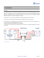
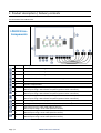
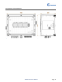
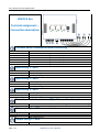
LPB DC3 Eco Lightning Protection
User’s Manual
Edition 3.0
July 2011
Documentation History
Edition
1.0
2.0
3.0
Revision / Supplement
First Edition April 2011
June 2011: New logo
July 2011: Product name changed
Edition 3.0
PADCON reserves the right to make alterations to its products in the interest of technical progress. These
alterations need not be documented in every single case.
This manual and the information contained herein have been compiled with due diligence. However,
PADCON assume no liability for printing or other errors or damages arising from such errors.
The brand names and product names used in this document are trademarks or registered trademarks of the
respective title owner.
Page | 2
LPB DC3 Eco User’s Manual
Content
LPB DC3 Eco Lightning Protection User’s Manual .......................................................................................................1
Documentation History ........................................................................................................................................2
Content .................................................................................................................................................................3
1. Introduction ......................................................................................................................................................5
1.1 Usage ..........................................................................................................................................................5
2. Product description / Delivery contents...........................................................................................................6
2.1 Overview of the LPB DC3 Eco .....................................................................................................................6
2.2 Delivery contents .......................................................................................................................................7
3. Technical data and documents.........................................................................................................................8
3.1 Specifications .............................................................................................................................................8
3.2 Dimensions of the LPB DC3 Eco .................................................................................................................9
4. Installation / Connection ............................................................................................................................... 10
4.1 Installation............................................................................................................................................... 10
4.1.1 Place of installation ........................................................................................................................ 10
4.1.2 No direct weather influence........................................................................................................... 10
4.1.3 Cable connection ............................................................................................................................ 10
4.1.4 Installation of the housing.............................................................................................................. 11
4.1.5 Mechanical installation of the LPB DC3 Eco ................................................................................... 11
4.1.6 Horizontal mounting ...................................................................................................................... 11
4.1.7 Realize drip off loop for inputs ....................................................................................................... 11
4.1.8 Cable conduct ................................................................................................................................. 11
4.2 Electrical installation ............................................................................................................................... 11
4.3 Connection of the LPB DC3 Eco ............................................................................................................... 12
4.4 Tightening torques and conductor cross sections .................................................................................. 13
5. Function ......................................................................................................................................................... 13
6. Function check ............................................................................................................................................... 14
6.1 Check of the connectors.......................................................................................................................... 14
6.1.1 Visual check .................................................................................................................................... 14
6.1.2 Mechanical check ........................................................................................................................... 14
6.1.3 Electrical check ............................................................................................................................... 14
6.2 Electrical check ........................................................................................................................................ 14
7. Fault analysis / Decommissioning ................................................................................................................. 15
LPB DC3 Eco User’s Manual
Page | 3
7.1 Fault analysis ........................................................................................................................................... 15
7.2 Decommissioning and demounting of the LPB DC3 Eco ......................................................................... 15
8. Safety instructions ......................................................................................................................................... 16
9. Maintenance.................................................................................................................................................. 18
10. Spare parts................................................................................................................................................... 18
11. Service / Contact.......................................................................................................................................... 19
Page | 4
LPB DC3 Eco User’s Manual
1. Introduction
1.1 Usage
The PADCON LPB DC3 Eco is a protection device against overcurrent and overvoltage by lightning. The LPB
DC3 Eco is connected between the photovoltaic generators and the inverters. Overvoltage caused by
lightning is discharged to earth as well from the plus line as the minus line. Thus the inverters installed
behind the LPB DC3 Eco are protected against overvoltage.
3 strings (plus and minus) are protected against overvoltage by lightning by the LPB DC3 Eco.
The used arresters match highest market demands and therefore ensure maximum safety.
The LPB DC3 Eco is connected between the photovoltaic generators and the inverter and protects your
inverter of the effects of a lightning stroke to your plant.
The LPB DC3 Eco is delivered with plant specific connectors.
The LPB DC3 Eco is delivered with an integrated roof and therefore is immediately applicable for outdoor
installations.
Figure 1: Overwiew
LPB DC3 Eco User’s Manual
Page | 5
2. Product description / Delivery contents
2.1 Overview of the LPB DC3 Eco
LPB DC3 Eco Components
Cypher Number Description
1
Combined arrester for string 1.
1
Combined arrester for string 2.
1
Combined arrester for string 3.
1
Terminal block for the combined arrester monitoring.
1
Pressure compensation.
1
Pressure compensation.
1
1
1
1
1
1
1
Plus input string 1: MC4 male receptacle (optional other connectors).
Minus input string 1: MC4 female receptacle (optional other connectors).
Plus input string 2: MC4 male receptacle (optional other connectors).
Minus input string 2: MC4 female receptacle (optional other connectors).
Plus input string 3: MC4 male receptacle (optional other connectors).
Minus input string 3: MC4 female receptacle (optional other connectors).
Dewatering and ventilation plug.
1
Cable gland for the protective conductor (1m NYY-J, 1 x 16 mm2).
1
1
1
1
1
1
Plus output string 1: 0.5m cable (ideal for Sunclix).
Minus output string 1: 0.5m cable (ideal for Sunclix).
Plus output string 2: 0.5m cable (ideal for Sunclix).
Minus output string 2: 0.5m cable (ideal for Sunclix).
Plus output string 3: 0.5m cable (ideal for Sunclix).
Minus output string 3: 0.5m cable (ideal for Sunclix).
Table 1: LPB DC3 Eco - Components
Page | 6
LPB DC3 Eco User’s Manual
2.2 Delivery contents
•
•
•
LPB DC3 Eco
User’s Manual
1m NYY-J, 1 x 16 mm2, protective conductor (already connected to one side)
LPB DC3 Eco User’s Manual
Page | 7
3. Technical data and documents
3.1 Specifications
HOUSING:
Open field installation
UV resistance
Material
Coloring
Wall mounting
Leaded
Yes
Yes, conforming to UL 508
Polymer plastic
RAL 7035
Yes
Yes
INPUT:
Maximum PV voltage [Upv max]
Input DC side
≤ 1000 V
3- (MC4 female recetacles) / 3+ (MC4 male receptacles)
OUTPUTS:
Outputs 3-/3+
3 minus outputs: 0.5 m cable
3 plus outputs: 0.5 m cable
30 A
NYY-J 1x16 mm2 cable, 1 m total length
Nominal output current [INom]
Earth connection
DIMENSIONS AND WEIGHT:
Housing width/height/depth [mm]
Weight
460 / 370 / 245
5 kg
STANDARDS:
CE conformity
Yes
PROTECTIVE CLASS AND ENVIRONMENTAL
CONDITIONS:
Protection class conforming to EN 60529
Valid surrounding temperature (T in °C)
Rel. air humidity non condensing ( U Air)
Max. height over mean sea level (MSL)
IP 65
-40 °C…+50 °C
Up to max. 90%
2.000 m
FURTHER PROPERTIES:
SPD according to EN 61643-11/ EN 61643-11
Nominal voltage (Uocstc) Un DC
Max. continuous voltage (Ucpv), Uc DC
Max. discharge current (8/20) µs, Imax
Nominal discharge current (8/20) µs, In
Lightning impulse current (10/350) µs, Iimp
Protection level for In, Up
Protection level for 5 kA, Up
Protection level for Imax, Up
Leakage current / operating current IC / IB
Follow current, If
Follow current extinguishing capability, Ifi
Response time, tA
Short circuit resistance IPE
Page | 8
Type 1+2 / Class I+II / B, C
1000V
1200 V
40 kA
20 kA
12.5 kA
< 2.8 kV
< 2.3 kA
< 3.7 kA
No
No
Infinite
≤ 25 ns
25 kA
LPB DC3 Eco User’s Manual
3.2 Dimensions of the LPB DC3 Eco
Figure 2: Front view
Figure 3: Side view
LPB DC3 Eco User’s Manual
Page | 9
4. Installation / Connection
onnection
Danger:
Danger of life by electrical shock !
High DC voltages are attached to the different components of the LPB DC3 Eco.
•
•
•
All works described in this manual must exclusively be executed by qualified technical personal. Qualified means that
the personal has to be trained corresponding the task that has to be executed.
All safety instructions mentioned in the user’s manual have to be obtained working on the LPB DC3 Eco. The personal
has to be familiar with the content of the user’s manual.
If you can not repair an error with help of this manual, immediately contact PADCON.
4.1 Installation
4.1.1 Place of installation
•
•
•
•
Easily accessible.
Connections have to be accessible.
No constraining
training objects in immediate surrounding.
Allow possibility for yearly maintenance (mowing the lawn, cleaning housings,…).
4.1.2 No direct weather influence
•
•
•
Avoid direct, strong sun irradiation.
Protect against direct rain.
Protect against standing water.
4.1.3 Cable connection
•
•
•
Cables to the bottom.
Observe polarity.
Retighten cable glands.
Page | 10
LPB DC3 Eco User’s Manual
4.1.4 Installation of the housing
•
•
•
Mount housing tension free.
Avoid
id mechanical tension by screws.
Adjust mechanical tensions with buffers if necessary.
4.1.5 Mechanical
cal installation of the LPB DC3 Eco
•
•
•
Solid and even mounting surface.
Observe complete rest of the flange area of the optional available mounting
mounting brackets.
Use all four fastening screws.
4.1.6 Horizontal mounting
•
Check mounting and
nd repair if necessary.
4.1.7 Realize drip off loop for inputs
•
•
Imply reserve.
No horizontal cable routing.
4.1.8 Cable conduct
•
•
•
Avoid mechanical tension of inputs.
Conduct cables
bles without mechanical tension.
Avoid crossings in wiring.
4.2 Electrical installation
1.
2.
3.
4.
5.
6.
7.
8.
9.
Disconnect the inverter on the AC side.
Switch the inverter currentless on the DC side.
Mount the LPB DC3 Eco.
Connect the protective conductor
ductor (PE).
Connect the inputs of the LPB DC3 Eco.
Eco
Connect the outputs of the LPB DC3 Eco with the inverter.
Switch on the current on the DC side.
si
Put the inverter into operation.
We recommend to check the polarity and height of voltage of the strings before installation and to
calibrate the input values
lues of the inverter after
afte installation.
Danger:
The five safety rules !
The five safety rules:
•
•
•
•
•
Disconnect
Secure against restart
Check absence of voltage
Earth and short circuit
Fence off and cover adjacent, live parts
LPB DC3 Eco User’s Manual
Page | 11
4.3 Connection of the LPB DC3 Eco
LPB DC3 Eco
Terminal assignment –
Connection description
Terminal block: Combined arrester monitoring
Terminal no
1
4
2
5
3
6
Line description
Combined arrester for string 1: contact 1 (ncc)
Combined arrester for string 1: contact 2 (ncc)
Combined arrester for string 2: contact 1 (ncc)
Combined arrester for string 2: contact 2 (ncc)
Combined arrester for string 3: contact 1 (ncc)
Combined arrester for string 3: contact 2 (ncc)
Input string 1 – MC4
MC4
MC4 male receptacle
MC4 female receptacle
Line description
Plus input string 1
Minus input string 1
Input string 2 – MC4
MC4
MC4 male receptacle
MC4 female receptacle
Line description
Plus input string 2
Minus input string 2
Input string 3 – MC4
MC4
MC4 male receptacle
MC4 female receptacle
Line description
Plus input string 3
Minus input string 3
Protective conductor terminal (PE) of the combined arrester
Terminal no
PE
Line description
Protective conductor clamping range: 1.5 - 25 mm2. cable: 1m NYY-J, 1 x 16 mm2
Output string 1 – MC4
Solar cable
1 x 6 mm2
1 x 6 mm2
Line description
Minus output string 1
Plus output string 1
Output string 2 – MC4
Solar cable
Page | 12
Line description
LPB DC3 Eco User’s Manual
1 x 6 mm2
1 x 6 mm2
Minus output string 2
Plus output string 2
Output string 2 – MC4
Solar cable
1 x 6 mm2
1 x 6 mm2
Line description
Minus output string 3
Plus output string 3
Table 2:
Caution:
The length of the protective conductor must not exceed 1 meter!
The length of the protective conductor must not exceed 1 meter (bus bar plus cable).
4.4 Tightening torques and conductor cross sections
Note:
Observe the tightening torques !
The tightening torques have to be observed during connection of the protective conductor (PE).
Conductor cross sections and torques
Line
Cross section
Torque
Plus inputs
Plus outputs
Minus inputs
Minus outputs
Protective conductor
6 mm2
6 mm2
6 mm2
6 mm2
16 mm2, screw terminal
10 Nm
Table 3: Conductor cross section
5. Function
The PADCON LPB DC3 Eco is a protection device against overcurrent and overvoltage by lightning. The LPB
DC3 Eco is connected between the photovoltaic generators and the inverters. Overvoltage caused by
lightning is discharged to earth as well from the plus line as the minus line. Thus the inverters installed
behind the LPB DC3 Eco are protected against overvoltage.
3 strings (plus and minus) are protected against overvoltage by lightning by the LPB DC3 Eco.
LPB DC3 Eco User’s Manual
Page | 13
6. Function check
Warning:
Do not open the LPB DC3 Eco !
The LPB DC3 Eco is leaded and must not be opened. In case of damage or destruction of the sealing expires the guarantee
and liability by Padcon.
Refer to your supplier or to Padcon (www.padcon.de) for function check. The LPB DC3 Eco is leaded and
must not be opened by unauthorized personnel.
6.1 Check of the connectors
6.1.1 Visual check
•
•
•
•
•
Completeness of wiring
Snap in of the clips
Proper input wiring
Proper fit of connectors
Possible danger for man and material
6.1.2 Mechanical check
•
•
•
Tight fit of connectors
Tightening torque of cable glands
Pull off test of connectors
6.1.3 Electrical check
•
•
•
Check correct polarity
Appropriate string current flow . See 7. Fault analysis / Decommissioning.
Appropriate open circuit voltage. See 7. Fault analysis / Decommissioning.
6.2 Electrical check
•
•
Polarity of the current direction
Compare input and output current
Page | 14
LPB DC3 Eco User’s Manual
7. Fault analysis / Decommissioning
7.1 Fault analysis
Fault analysis
Visual inspection
Fault description
Measure
Damage of the housing.
Damage of the cable glands.
Damage of the cables.
Damage of the male orr female receptacles.
Damage of the dewatering and
nd ventilation plug.
Damage of the pressure compensation elements.
The LPB DC3 Eco has
as to be changed.
The LPB DC3 Eco has
as to be changed.
The LPB DC3 Eco has
as to be changed.
The LPB DC3 Eco has
as to be changed.
The LPB DC3 Eco has
as to be changed.
The LPB DC3 Eco has
as to be changed.
Voltage check - Polarity
Nominal voltage nonexistent.
Polarity reversal.
The wiring has to bee checked.
Correct polarity.
Current check - Polarity
The input current of the
he inputs has to be equal to the
output current.
Polarity reversal.
The wiring has to bee checked.
Correct polarity.
Ground fault error – Insulation
nsulation fault
Ground fault error.
The wiring has to bee checked.
Table 4: Fault analysis
7.2 Decommissioning and demounting of the LPB DC3 Eco
Danger:
Danger of life by electrical shock !
High DC voltages are attached to the different components of the LPB DC3 Eco.
•
•
•
1.
2.
3.
4.
5.
6.
All works described in this manual must exclusively be executed by qualified technical personal. Qualified means that
the personal has to be trained corresponding the task that has to be executed.
All safety instructions mentioned in the user’s manual have to be obtained working on the LPB DC3 Eco. The personal
has to be familiar with the content of the user’s manual.
If you can not repair an error with help of this manual, immediately contact PADCON.
Disconnect the inverter on the AC side.
Switch the inverter currentless on the DC side.
Disconnect the outputs of the LPB DC3 Eco from the equipment.
Disconect the inputs of the LPB DC3 Eco from the generator.
Disconnect the protective conductor (PE).
Demount the LPB DC3 Eco.
LPB DC3 Eco User’s Manual
Page | 15
8. Safety instructions
General
1.
2.
3.
4.
The LPB DC3 Eco only must be opened and installed by trained electrotechnical specialists
Consider the installation instructions in this manual
Consider the installation instructions of the used inverters and other connected devices
Consider the standards and rules as
• BGV A1/A2: Common trade association safety instructions for electrical installations / equipment
• DIN VDE 0100-712:
712: Solar photovoltaic power supply systems (requirements for industrial premises, rooms and plants)
• VDI 6012 VDI Guide line: Decentralised energy systems in buildings, photovoltaic
• IEC 62548/ IEC82/514/CD: Installation and safety requirements for photovoltaic (PV) generators
• DIN VDE 0100-534
5. Inspect the LPB DC3 Eco for damages before installation, that can prevent the functional and safety operation of the LPB DC3 Eco
6. In case of violation of the installation instructions mentioned in this manual expires the warranty and the liability
Validity
This documentation describes how to install and operate a LPB DC3 Eco.
Target group
This documentation is intended for installers and operators of PV systems which are realized with the LPB DC3 Eco.. It includes a description of how to
install, operate the LPB DC3 Eco.
Explanation of the Symbols Used
In this document, the following terms and symbols are used to describe different hazard levels:
Danger indicates a hazardous situation which, if not
avoided, will result in death or serious injury.
Danger
Warning indicates a hazardous situation which, if not
avoided, could result in death or serious injury.
Warning
Caution indicates a hazardous situation which, if not
avoided, could result in minor or moderate injury.
Caution
Storage of documentation
This operating manual, the installation guide, the data sheets, the operating manuals of installed components, and the wiring diagrams must be kept
in the immediate vicinity of the LPB DC3 Eco.. They must be available to operators and maintenance
maintenance staff at all times.
Failures and correction
Failures that can affect the safety, have to be removed immediately. Impermissible change and the use of spare parts, that are not recommended
from PADCON can cause fire, material damage or electrical shocks.
shoc Unauthorized persons must nut have access to this devices. Instruction labels have
to be readable properly and have to be replaced immediately if damaged.
Page | 16
LPB DC3 Eco User’s Manual
Appropriate usage
Appropriate use of the LPB DC3 Eco means following all instructions in the installation manual relating to installation, electrical connection, and
commissioning of the equipment. Any deviation from the instructions in this manual is regarded as inappropriate use of the equipment. PADCON
accepts no responsibility or liability for any and all damage resulting from inappropriate use of the equipment.
Appropriate use of the equipment also entails:
• Observation of the safety instructions listed here and in the following sections
• Observation of the instructions in the user manual
• Conformance to the device-dependent
dependent technical data
Personnel
Only qualified technical personnel may perform any and all work on the LPB DC3 Eco.. Qualified means that the personnel must possess training
relevant to the activity performed and must be familiar
familiar with the content of this manual. The personnel must have read and understood the safety
section in this manual.
About this manual
This manual was written with the greatest possible care. However, discrepancies cannot be excluded. PADCON accepts no responsibility
re
or liability for
injury to persons, or material damage caused by mistakes in this manual.
Checking the delivery
Upon receipt of the equipment, check the packaging and the device for any possible damage and compare the contents of the delivery with the
delivery documentation. In the case of damage to the device and/or unclear delivery contents, please immediately contact PADCON GmbH (see
contact address on the last page).
Storage
The PADCON LPB DC3 Eco may only be stored in rooms protected
prot
from dust and moisture.
Installation
The requirements relating to the installation site, the manner of installation and the mounting position must be observed. In addition to this, the
following points must be noted.
roof
•
The installation location must be easily accessible and offer a secure base for working on the device. This is especially important for roofmounted systems.
•
The LPB DC3 Eco is built using the latest technology, according to recognized safety standards. Despite this, a fault resulting
result in arcing cannot be
ruled out. This can result in melting of the enclosure as well as fire and smoke, which may represent a hazard to personnel or
o equipment. This
must be taken into consideration upon installation.
•
The equipment may not be installed near to inflammable materials. If this cannot be avoided, preventative measures must be taken, which
prevent fire and smoke from spreading.
•
The equipment may not be installed in critical areas, escape routes, living spaces or office spaces.
Special Hazards
rds of Photovoltaic Systems
Photovoltaic systems have special characteristics representing special hazards that are described here. An active power source
sourc is connected, which
means that depending on the operating mode there may be voltage present, from the
the photovoltaic generator and/or the LPB DC3 Eco. This is
especially important to note when disconnecting the LPB DC3 Eco. High DC voltages are connected (no zero-crossing),
crossing), that in case of error, or
unproper use of fuses or connectors, may result electric arcs. The short-circuit
circuit current of the photovoltaic generator is only slightly higher than the
maximum operating current and is also dependent on the level of solar radiation, which means that if a short circuit occurs in
i the system, the existing
circuit breakers
reakers are not guaranteed to switch off. A highly branched generator array may be difficult to disconnect if a fault develops (e.g. short
circuit). We recommend the additional use of the optionally available DC circuit breaker for disconnecting the inverter.
invert
Changes, modifications or additions of the LPB DC3 Eco
Danger:
Danger in case of changes, modifications or additions of any components of the LPB
DC3 Eco !
No changes, modifications or additions of any components of the LPB DC3 Eco are allowed without prior agreement of Padcon.
LPB DC3 Eco User’s Manual
Page | 17
9. Maintenance
Danger:
Danger of life by electrical shock !
High DC voltages are attached to the different components of the LPB DC3 Eco.
•
•
•
All works described in this manual must exclusively be executed by qualified technical personal. Qualified means that
the personal has to be trained corresponding the task that has to be executed.
All safety instructions mentioned in the user’s manual have to be obtained working on the LPB DC3 Eco. The personal
has to be familiar with the content of the user’s manual.
If you can not repair an error with help of this manual, immediately contact PADCON.
Following table gives an overview of the different maintenance working that have to be led through at the
LPB DC3 Eco and the recommended maintenance interval.
LPB DC3 Eco - Maintenance
Maintenance working
Check the terminal clamps of the
he string wiring for solidity and retighten if required.
Visually check the insulation
sulation and the terminals. Thereby look after changes and
discoloring of the material. Immediately change
c nge defect or corroded lines, contacts and
connectors.
Check the correct and horizontal
orizontal mounting of the LPB DC3 Eco.
Check the locks of the
he cover of the LPB DC3 Eco for free movement and correct function.
Check the cable glands for
or tightness and firm fit. Immediately change defect or untight
ntight
cable glands.
Check if condensing water has
as accumulated in the LPB DC3 Eco.
Check the earth connection respectively
espectively the contact resistance of the protective
conductor.
Check the climate elements dewatering and ventilation plug and pressure compensation
for pollution respectively damage. The LPB DC3 Eco has to be changed in case of fault.
Check the mounting place of the LPB DC3 Eco for easy access, secure stand and
flammable materials.
Table 5: Maintenance
10. Spare parts
Following spare parts are available for the LPB DC3 Eco:
•
•
•
•
•
Male, female receptacle inclusive
lusively cable
Combined arrester
Mounting kit
Cable glands
Tools
Page | 18
LPB DC3 Eco User’s Manual
Interval
12 month
12 month
6 month
6 month
6 month
12 month
12 month
12 month
11. Service / Contact
PADCON GmbH
Steigweg 24, Gebäude 44
97318 Kitzingen
Germany
Tel: +49 (0) 9321.2680-200
Fax: +49 (0) 9321.2680-9200
E-Mail: info(at)padcon.com
www.padcon.com
Service and Complaint
Your primary point of contact for any service issues is Sascha Machner with his
competent team.
Tel: +49 (0) 9321.2680-222
e-mail: service(at)padcon.com
LPB DC3 Eco User’s Manual
Page | 19


![Indicateurs (PDF/782Ko) [F]](http://vs1.manualzilla.com/store/data/006364555_1-61d6515c96ce437ed2545f3e53fb26c1-150x150.png)


![Régulateurs (PDF/1,26Mo) [F]](http://vs1.manualzilla.com/store/data/006367628_1-d11067c6e30136a71de027b5803c5ae5-150x150.png)