1
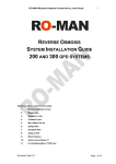
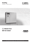
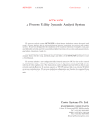
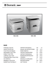
User Manual Version 2013.06 Aquatec watermaker DC 320 Modular 12 or 24 Volt DC Thank you to choose an AQUATEC Watermaker for the provisioning of fresh water on your boat. AQUATEC equipment is made from high-quality components exclusively and has proven its reliability on longcruising-yachts. We are convinced that our product will serve you for many years without interferences. To ensure total satisfaction, please read this user manual carefully and always use the update version. Download the latest manual at www.aquatec-watermaker.de. Manufacturing and marketing by AQUATEC-Watermaker, Owner Joachim Matz, Bgm.-Schinkel-Str. 10a , 25348 Glückstadt, Germany. Tel: +49(0)151 50933262 Mail: [email protected] web: www.aquatec-watermaker.de Copyright Joachim Matz 2 Table of contents 4-5 Fresh water production 6-7 Fresh water flushing 8 -10 Preservation / cleaning 11 Introduction 12 - 16 Installation guide 17 Circuit diagram 18 Maintenance / tighten belt 19 Change of membranes 20 Troubleshooting 21 Clamping torques / Spare parts 22 Technical data 23 Scope of delivery 24 - 25 Warranty notes Installation conservation / cleaning tank 3 Operating instructions Attention Do not operate your water maker with unpurified seawater (oil, chlorine or other chemicals). The R.O. membranes are conserved with a dissolution that, when ingested, can cause irritations of the gastrointestinal tract. For that reason, the product water must not be consumed within the first 30 minutes of operating time, beforehand it has to be drained over the test-outlet. This applies accordingly after temporary shutdown or cleaning of the membranes with the cleaning chemicals. Placing into operation Check oil level and condition of the oil of the high-pressure pump. 1) Open the seawater intake valve. 2) The pressure control valve in the control panel has to be fully opened by turning counter clockwise. Attention: Never start your Aquatec with closed pressure control valve! Starting with a closed valve destroys the pressure reading and possibly essential parts of the equipment. An open pressure control valve can be seen when the first two threads of the valve body becoming visible by turning the pressure control wheel. 3) Turn three-way valve (4) according to the flow diagram to position fresh water production. Turn three-way valve (2) to position test-outlet. 4) Switch on the feed pump. De-aerate the plant if necessary. 5) Switch on the high-pressure pump. De-aerate the system and control the drain water. Inspect the whole system for leakages. 6) Increase the pressure at the pressure control valve by slowly turning it clockwise to about 30 bar. Let the system work for about 30 seconds. There should not be any air pockets visible in the system. 7) Increase the pressure stepwise up to the working pressure (55-60 bar). Test the product water by tasting (at daily operation, the product water should be salt-free after about 60 seconds). By shifting the three-way valve no. 2, the product water is fed into the fresh water tank. Attention: If Aquatec is run in brackish water or in low-salt water (e.g. Baltic Sea), the fresh water production must not exceed the displayed value! In this case, increase the pressure under continuous observation of the produced amount of water until the normal level of fresh water production is reached. 4 Flow diagramm fresh water production. Working pressure 55- 60 bar !!! 5 Switch off the system 1) Open the pressure control valve until the plant runs without pressure. 2) Run the Aquatec several minutes to remove the concentrated salt from the membranes. 3) Turn three-way valve (2) to position test-outlet. 4) Switch off the high-pressure pump first and then the feed pump. 5) Close the seawater intake valve. 6) Rinse with chlorine-free fresh water. A fresh water flushing of the Aquatec is recommended after each operation. It avoids biological growth in the membrane and preserves the life span and the reliability of the entire system. Fresh water flushing procedure After each operation, the Aquatec should be rinsed with chlorine-free fresh water. About 8 liters fresh water is needed per membrane. After fresh water flushing, the system may remain unused for 6 days. This process can be repeated every 6 days. Note: Prior to a longer period of shutdown (without flushing), the Aquatec has to be preserved with the chemical no. 3 (Biocide). For instructions, see “Long term preservation (mothballing) of the plant”. Instructions for fresh water flushing. Working pressure 0 bar!!! 1) Close the seawater intake valve. 2) Open the pressure control valve entirely, turn the product water three-way valve (2) to test-outlet position. 3) Turn three-way valve (4) according to the flow diagram of fresh water flushing. Open valve (3). The fresh water pressure pump of the boat should turn on now. Hint: Please find out the required amount of flushing water by discharging the rinsing water into a bucket once after a normal operation (take off the hose at the thru-hull fitting) and check the salinity constantly by tasting. During the process, stop the time to find out the time requirement of future flushes. By collecting it in a bucket, you also find out the needed amount of flushing water. 5) Close valve (3). 6 Flow diagram fresh water flushing. Working pressure 0 bar. 7 Long term preservation (mothballing) of the plant Prior to a longer period of shutdown, the Aquatec has to be preserved with chemical no. 3 (Biocide). After mothballing, the plant can be shut down for 6 months, depending on the environmental conditions. For a longer period of shutdown, the long term preservation has to be repeated every 6 months. If there is the risk of frost, the entire pressure pipe with internal membrane in the pipe should be dismounted (after necessary preservation) and be stored frost-proof with closed hose connections. Water in the filters, feed pump and in the high-pressure pump has to be drained. Can the membrane not be removed alternatively 20% glycerin in food quality can be added as an antifreeze to the biocide at preservation. Attention: The conservation chemical no. 3 is a Biocide. Please consider the hazard notes on the canisters. Working with chemicals, please wear protective glasses, breathing protection and rubber gloves for your own safety. Instruction for mothballing of the Aquatec. Working pressure 0 bar!!! 1) Close the seawater intake valve. 2) Open the pressure control valve entirely, turn the product water three-way valve (no. 2) to position test-outlet. 3) Rinse the system with fresh water as described in “Fresh water flushing”. 4) Turn the three-way valve (4) according to the flow diagram “Long term preservation (mothballing) of the plant”. Open valve (1). 5) Mix the required amount of Biocide corresponding to the instructions on the package (chemical no. 3) with 1 to 2 litres chlorine-free freshwater, until the powder is fully dissolved. Since there are about 1,5 liters of water already in each membrane and 1 liter of water in each filter, please add the according amount of chemical to the water that has to be blended in every membrane and filter. 6) Fill the solution into the tank for conservation. 7) Switch on the feed pump and the high-pressure pump. Let the Biocide circulate through the system for about 10 minutes. 8) The Biocide in the tank can be discharged overboard after turning the three-way valve (4). It should be noted that the system gets no air. Switch off the system immediately before the tank has been completely emptied. 9) Possibly turn the valves in a position that prevents leakage of conservation liquid from the membranes. The Biocide should stay in the system to prevent that the membranes dry out. Attention: At every recommissioning after cleaning or mothballing, divert the product water over the test-outlet for the first 30 minutes to rinse the chemical completely out of the system. 8 Flow diagram long term preservation (mothballing) and cleaning Working pressure 0 bar. 9 Cleaning of the Aquatec. Working pressure 0 bar!!! When the fresh water production decreases more than 15 %, the membrane should be cleaned chemically. Attention: Cleaning chemical no. 1 is alkaline and cleaning chemical no. 2 is an acid. Please consider the hazard notes on the canisters. Working with chemicals, please wear protective glasses, breathing protection and rubber gloves for your own safety. 1) Close the seawater intake valve. 2) Open the pressure control valve entirely, turn the product water three-way valve (2) to test-outlet position. 3) Rinse the system with fresh water as described in “Fresh water flushing”. 4) Turn the 3 three-way valve (4) according to the flow diagram “Long term preservation (mothballing) of the plant”. Open valve (1). 5) Blend about 3-5 liters warm chlorine-free fresh water, temperature appr. 25° Celsius (77° Fahrenheit), with chemical no. 1 (Alkaline), according to the instructions on the package. Since there are about 1,5 liters of water already in each membrane and 1 liter of water in each filter, please add the according amount of chemical to the water that has to be blended in every membrane and filter. 6) Switch on the feed pump and the high-pressure pump. The unit is run for an hour or so to circulate the solution through the membrane, then allowed to rest for an hour, and then run again for 15 minutes. 7) After this, the system is put back into service, unpressurized, and run for 15 minutes or so to clear out the cleaning solution, before being returned to regular service. Once again, the initial product water will need to be discharged over the testoutlet. 8) If there is no change in freshwater output, repeat the procedure 1 to 7 with chemical no. 2 ( Acid). Attention: Do must not mix different chemicals. Prior to a longer period of shutdown, the Aquatec has to be preserved with Biocide after cleaning and flushing. 10 Introduction The principle of reverse osmosis (RO) In natural sciences and technology, osmosis is perceived as the directed migration of molecules through a semi permeable membrane. The chemical and physical structure of the membrane determines which molecules are able to pass and which are not. For this reason, it is called semi-permeable, which means as much as halfway or partial permeability. If one mixes different liquids, like in this case water with different salinities, they aim to equalize their concentration. That way, the seawater would be thinned out and the drinking water would be enriched with salts. The effect would be a less concentrated, homogeneous dissolution. Pouring sea- and fresh water in equal amounts into a container where both liquids are separated by an adequate semi-permeable membrane, there would be one side with seawater that is highly loaded with salts, on the other side more or less “clean” water without or with little dissolved components. The natural tendency of both liquids to equalize their salinity leads to the migration of water molecules from the fresh water side towards the seawater side. As a result, the volume of water on the fresh water side decreases while it increases on the seawater side. This process of osmosis takes place until the pressure on the seawater side is in accordance with the osmotic pressure. Then it stops. In this case, the osmotic pressure is around 30 bar. The described process however is reversible by exposing the liquid on the seawater side to mechanical pressure. At a pressure of 30 bar, the osmotic process cannot take place or would rather be reversed. When pressure is increased beyond 30 bar, for instance 60 bar, water molecules from the seawater side migrate to the fresh water side. All other components of the seawater dissolution are not able to pass the membrane. As a result, the dissolution on the seawater side remains highly-concentrated while there is a gain of fresh water on the other side of the membrane. This process is referred to as reverse osmosis (R.O.) The seawater is delivered to the pressure pipe’s entry side of a RO-system by a highpressure pump. The osmotic membrane is located in the pressure pipe and is merely permeable for the vehicle “water“ (solvent) and detaining the soluted substances. When the pressure difference is more than leveling out the osmotic head, the water molecules are able to pass the membrane that works like a filter, while the “unpurified” molecules are detained. In opposite to a classic membrane-filter, osmosis membranes do not have continuous pores. In fact, the ions and molecules are migrating through the membrane by diffusing through the membrane material. Inside of the membrane, the permeat-tube is located which transports the fresh water through one of the two end caps of the pressure pipe towards the fresh water tank. The excess seawater, now referred to as concentrate (brine), is drained off overboard through the outlet of the pressure pipe by a pressure control valve. 11 Installation guide page 1 Hose dimensions (inner diameter) Thru-hull fitting 1/2" = 13 mm feed from sea cock up to high-pressure pump ½“ = 13 mm Preservation and cleaning: From cleaning tank to HP pump ½“ = 13 mm Drain over board (Brine): ½“ = 13 mm inside. Fresh water flushing ½“ = 13 mm inside. Product water John Guest PE tube 10 mm. HP hose: ¼“ = 6 mm inside. During assembly of the hose nozzles and fittings, 3-4 windings of Teflon-tape have to be wrapped around the screw thread against screw direction as tightly as possible. The grommets may not be screwed too tightly in the filters or stop-cocks. If possible, install hoses moved upward from the thru-hull fitting to the filters and up to the highpressure pump. This will prevent accumulation of air in the hoses. Thru-hull fitting and coarse filter and feed pump Install a thru-hull fitting, preferably deep under water line, afterwards install eventual a coarse filter for protection the feedpump. The thru-hull fitting, coarse filter and the feed pump have to be located in an area that will always be under the waterline when the boat is used under normal running conditions. Install the feed pump close as possibly to the thru-hull fitting. The pump must be flooded before turn on, otherwise the bearings will be destroyed by drought. The system has to be fully de-aerated by means of the feed pump. To allow any air to escape, switch the pump on and off several times. Please note: Depending on the type of boat, there might occur problems with the seawater intake at a speed of more than about 8 knots. Mounting position of the feed pump Attention: Connection feed pump: red = positive (+), black = negative (-). Wrong polarity destroys the pump and is not covered by warranty. 12 Installation guide page 2 Filter housing For a good sealing of the filter housing, please lubricate the O-rings in the filter bowls with the included acid-free silicone grease. Mount the filter housing at an easily accessible place. Connect the filter inlet with the outlet of the feed pump and the filter outlet via PVC hose with the high-pressure pump. Secure all hose connections with stainless steel hose clamps. Install all hose connections in a way that air accumulations are avoided. Fresh water pipe Installing the John Guest fittings Cut the 10 mm PE tube right-angled with a sharp knife to the required length. There may not remain any damage or brush marks at the tube. Push the tube straightly and without canting it into the fitting to the back stop. The tube may be removed at any time. For this purpose, only press back the clamp collar. (Possibly use a 10 mm open-ended wrench to disperse the pressure constantly on the retaining ring) Press back clamp collar Remove pipe Press back clamp collar Never block the product water line (valve etc.). This damages the membranes by means of back pressure. Remove the red cap from the John Guest fitting at the fresh water outlet of the membrane housing by pushing back the retaining ring. Direct the PE-fresh water pipe from the fresh water outlet at the membrane housing to the inlet at the flowmeter in the control panel. From the three-way valve (2), direct one pipe to the fresh water tank and one pipe to any test-outlet. Advice: A good place for the test-outlet is the sink or basin, where it can be installed by an additional water outlet without cut off cock. At this position, an easy control of the product water is possibly, furthermore you can bottle your drinking water here directly. This ensures that the quality of the drinking water will be best, since it does not have to follow a detour over the drinking water tank on-board. Attention: When the plant is switched off, chlorinated water (that possibly entered the tank at the last landside water intake) might flow back from the tanks into the membranes if the inlet is installed below the tank waterline. As chlorine destroys the R.O. membranes, a return flow from the tank has to be avoided. You can lead in the fresh water into the tank ventilation with a T-piece. A non-return valve must not be used. 13 Installation guide page 3 Fresh water flushing system Mount the filter housing for the charcoal filter at an easily accessible place between the fresh water pressure system and the prefilter housing. Install the hose connections corresponding to the flow diagram. Preservation and cleaning of the plant by the use of the flushing tank Mount the included flushing tank in a way that there is a slope to the feed pump and to the high-pressure pump. Control panel. Mount the control panel with vertical gauge at an easily accessible place. It always should be possible to control the hose connections. High-pressure pump unit Mount the pump unit horizontally in a cool, even, vibration-free place. A twist of the base plate must be avoided. After mounting, exchange the upper red plastic-srew in the crankcase for the dipstick with ventilation Membrane housing (pressure vessel) For the installation of the membrane housings athwart ships, inclined or vertical, the housings have to be secured in the retainers so that they don’t get out of place. Standard installation is horizontal, but any other angle is possible. For a inclined or vertical installation, the product water outlet and brine outlet has to be at the top. For horizontal installation, the fresh water outlet can be mounted at any side of the membrane housing. If, for your installation, the delivered fresh water connection on the side of the seawater outlet does not correspond to the conditions, you can correct that easily by changing the end caps (Screw tightening torque for the holding clips 3 Nm). Hose connections pressure vessel The pressure pipe is sealed with plastic-caps on the high-pressure connections. The product water connection is closed with a plastic plug that has to be replaced by the provided John Guest fitting after connection of the high-pressure hoses. This prevents a drying-out of the membrane which is impregnated with preservative liquid. The plastic- caps and the plug have not to be removed until immediately before commissioning to connect the high-pressure hoses and the product water hose. Hint: The membrane can be stored in the sealed pressure pipe for 6 weeks, preferably cool, but not above 20°C ambient temperature. However, we recommend to install the watermaker as soon as possible and to put it into operation. 14 Installation guide page 4 High-pressure hose, to be cut into two parts according to your needs. To allow a flexible assembly, the high-pressure hose is provided as one piece of 4 meters (13.1 feet) with a V4A high-pressure fitting at both ends. Please fit the required lengths accurately before cutting the hose. Note: The high-pressure hose may not be installed with a smaller radius than 6 cm. Assembly instruction for the two V4A high-pressure hose fittings: 1) Cut the hose with a clean 90º cut. 2) Screw the sleeve nut off the provided high-pressure hose fitting. 3) Wet the outside of the hose with a little bit of washing-up liquid. 4) Turn the sleeve nut onto the hose. Leave a gap of 2 mm between hose and shoulder of the screw nut to enable the hose expanding in length. 5) Wet the thread nipple of the fitting and the inside of the hose with a little bit of washing-up liquid. 6) Hold the sleeve nut with a wrench and screw the thread nipple with a second wrench into the hose. 7) Connect the pressure connection of the high-pressure pump and the entrance of the membrane housing with a hose. The flow direction of the seawater is indicated with an arrow on the pressure housing of the membrane. 8) The second high-pressure hose connects the outlet of the membrane housing with the inlet at the pressure control valve on the control panel. 9) Direct the brine from the outlet of the pressure control valve in the control panel through the three-way valve no. 4 via the plastic thru-hull fitting over waterline overboard. 15 Installation guide page 5 Connection of the high-pressure hoses with the pressure pipe: Secure the high-pressure connection fittings in the plastic end caps of the pressure pipe against twisting with a 19 mm open-ended wrench and tighten the union nut of the high-pressure hose with a 17 mm open-ended wrench with approx. 10 Nm. Due to the O-ring sealing it is not necessary to tighten the union nut with much force. Attention: Avoid over winding the body fittings in the plastic-end caps of the pressure pipe when attaching the high-pressure fittings to the membrane housing. The end caps can be damaged by over winding the fittings. Note: Only use cylindrical tread fittings (¼“ BSP) in the plastic-end caps of the pressure vessel. Taper threads may cause cracks. Connection product water pipe: After the connection of the high-pressure hoses, exchange the 1/4“ screw plug that seals the one-sided product water connection in the end cap for the supplied John Guest fitting. The John Guest fitting is due to its O-ring self-sealing and should be screwed in by hand without any tools Product water connection / John Guest connection High pressure connection / High pressure hose Hose connections on the control panel (1) (2) (3) (4) (5) (6) 16 (1) (2) (3) ½“ 13 mm PVC hose, concentrate (brine), overbord. ¼“ High-pressure hose, concentrate coming from outlet pressure pipe. Product water to freshwater tank. Product water to test-outlet. Product water, coming from freshwater-outlet pressure pipe. (4) (5) Circuit diagram for 12 / 24 volt systems, standard version The electrical connection has to be done by a professional installer. Attention: Connection feed pump: red = positive (+), black = negative (-). Wrong polarity destroys the pump and is not covered by warranty. Table for the required wire cross section DC 320 Total length in meter mm² 12V / 24V 5 10 / 4 10 16 / 6 15 25 / 10 20 35 / 10 25 35 / 16 S1 Switch feed pump (LP) S2 Switch relay high-pressure pump (HP) F1 Fuse for control and feed pump 10A / 5A F2 Fuse for high-pressure pump 12Volt 35A / 24Volt 20A Supply line for the switches feed pump and relay control 1,5 to 2,5 mm² The required cross section in mm² refers to the cable total length which results from the addition of the plus and minus cable lengths. Connecting cables and fuses are not included in scope of delivery. Switches in the control panel and the high current relay are included. As the output power of the plant depends on the tension of the driving motor, in the calculation of the wire cross sections a voltage drop of only appr. 2% should be estimated to provide for the maximum continuous output. 17 Maintenance In operation, regularly check all hose connections for leaks. Filter Coarse filter Prefilter Charcoal filter Maintenance Cleaning Replacement of filter elements Replacement of filter element High-pressure pump up to 25°C engine oil SAE 10-40 Oil change over 25°C car gearbox oil SAE 80-90 Valves HP / LP and seals quantity 0,36 liter = mid sight glass control Pressure regulation valve Anchor bolt cleaning / grease o-ring Time interval as required as required every 3 months initial change after 50 hours, then every 300 operating hours at the latest or once a year. Approximately after 1000 hours, or in case of leakages. Change of pump seals and possibly of The valves and plungers. About every 12 month Tensioning belt Warning: A loose belt jump over the teeth of the gears and will be damaged (indicated by a loud banging noise of the motor pump unit). Tension the belt by loosening the 4 nuts of the motor bolts. The motor bolts are secured in the base plate and cannot turn with. For tensioning, turn with e. g. a hammer handle between motor and pump in order to obtain pressure, if necessary. The belt should not give way if you press it down lightly with one finger. After the tension of the belt please check the alignment (eg ruler along the pulley). Service pressure regulation valve. To take the pressure pin out of the valve body, unscrew the adjusting knob. Then take off the spring with pressure disk. Now you see the pressure pin with a M3 tapped hole and pull it out by screwing in a M3 screw. Maintenance is limited to cleaning and silicone grease lubrication. The O-ring has only to be changed in case of leakage. 18 Pressure vessel Membranes The vent of the O-ring has to be directed to the water inlet product water seawater concentrate (brine) Demounting the membrane: For demounting the membranes, screw off the 3 M6x20 screws each at both ends. (Screw tightening torque for the holding clips 3 Nm). Then take off the stainless steel holding clamps. Thereafter, pull the end caps out of the pressure pipe with a slight pull at the stainless steel-fittings of the pressure hoses and slightly sidewise movements. The membrane has to be shoved out of the pressure pipe in flow direction, because the O-ring of the membrane prevents lateral movements against the flow direction. According to this, during assembly, the membrane has to be shoved in the pipe in flow direction. Before installation, all O-rings have to be lubricated lightly with acidfree silicone grease. When mounted, necessarily watch the O-rings to avoid damage. Before installation of the membranes, first fit the end cap on the side of the concentrate in order to thereupon shove the membrane against this cap. Important: To avoid that the new membrane dries out, it may only be removed from the plastic packaging just before commissioning the plant. The plastic film with the manufacturer's label on the membrane must not be removed. 19 Troubleshooting Pressure and/or production falls. low voltage coarse filter, prefilter or intake clogged membrane defect or dirty. check voltage at engine connections clean or replace filter clean or replace membrane Loud banging noise of the motor pump unit belt is too loose. tighten belt Noisy operation, vibrations, unsteady pressure. valve defective or soiled open valve caps and check valves, replace valves air pockets in supply pipes, membranes run feed pump und HP pump without pressure until there is no air left in system. inlet insufficient intake or filters clogged. Motor does not turn / Motor stops no voltage, fuse defective motor protection is activated due to overload motor protection is activated, but no overload check voltage, replace fuse reduce pressure, open pressure-valve adjust or replace motor protection switch Oil eakage between pump head and crankcase crankcase gasket rings defective replace gasket rings Water leakage between pump head and crankcase plunger(s) defective / o-rings plunger defective replace plunger(s)/ replace o-rings HP / LP seals defective replace seals Water in pump case high humidity (mostly), wrong oil. reduce oil change interval, use right oil Please note: Problems with watermakers are mostly caused by air in the system or clogged intake and filters. The drinking water production changes according to the salinity, the temperature of the seawater and the age of the R.O. membrane. The data regarding the fresh water production apply to a salinity of 35 grams/liter (Atlantic) at a temperature of 25ºCelsius (77°Fahrenheit) at the new membrane. A discrepancy up to 10% +/- is within the usual range. At current consumption, discrepancies of up to 5% +, especially in the first 50 hours of operation, are usual. 20 Clamping torques and spare part-numbers high-pressure pump No. 1 2 Description Pump head Duplexsteel 1,4462 Screw stainless 8 x 60 Amount 1 8 4 O-ring 17,13x2,62 NBR 90, Kit-1 6 5 Valveseat 1.4462, Kit-1 6 6 Valveplate 1,4462, Kit-1 6 7 Spring Kit-1 6 8 Valvebody KS, Kit-1 6 9 10 11 12 13 14 15 16 17 18 19 20 21 22 O-ring 20,24x2,62 NBR90 Nut 1,4462 M24x1,5 valve unit complete no. 4-8 Screw 8 x 10 Metal cover Spacer O-ring 55,56x3,53 Bearing gasket ring 18x26x6 Crankcase Dipstick Crank shaft Gib head Drive rod Kit-1 6 6 6 8 2 1 1 2 3 1 1 1 1 3 No. 23 24 25 26 27 28 29 30 31 32 33 34 35 36 39 40 41 42 43 44 45 46 Description Connecting rod eye O-ring 101,27x2,62 Top cover Screw 6 x 18 O-ring 10,82x1,78 Drain plug ¼“ x9 Gib Rosette Ring O-ring 5,28x1,78 Plunger Special ring Acorn nut M 8 gasket ring 25x62x10 Screw 8 x 16 Seal holder 1,4462 O-ring 28,3x1,78 Kit LP seals Thrust collar 1,4462 Kit HP seals Screw stainless ¼“ Screw plastic ½“ Amount 3 1 1 4 1 1 3 3 3 3 3 3 3 1 4 3 3 3 3 3 1 1 Remark to acorn nut no. 35: To unscrew, heat up to 250°. Secure the nut with loctite 270. To tighten the nut, a torque wrench has to be used. When ordering spare parts, please name the serial number of the pump head necessarily. 21 Technical Data Technical data AQUATEC watermaker DC 320 Membrane type Membrane Working Pressure Minimum Salt Rejection PH Range Free Chlorine Tolerance Seawater temperature range Water production Seawater SW 2540 Polyamide Thin-Film Composite 3.5% salinity, 55-60 bar, maximum 60 bar 99,5% 2 – 11 less than 0,1 ppm + 0.5°C to 38°C 32 liters/hour at 3,5% salinity, 25°C and 60 bar pressure Operating time HP pump Operating voltage of motor Operating voltage feedpump Operating time motor continuous duty 12.5 / 25 Volt 20 / 9,5 A 12.5 / 25 Volt 1,1 / 1,1 A continuous duty up to 45°C ambient temperature 22 Scope of delivery Seawater R.O. AQUATEC : High-pressure pump with electric motor, pump head in Duplex-stainless steel 1.4462. Feed pump 230 volt. GFK membrane housing and membrane-element. 1Filter housing and fastener, 1 charcoal filter-cartridge for fresh water flushing. 2 filter housing and fastener, 1 piece 25 and 1 piece 5 Micron filter-cartridge. 3 pcs. ball valves. Control panel with three-way valve ¼“ (no. 2 in flow diagram). Stainless steel high-pressure manometer, duplex-stainless steel pressure control valve., flowmeter, 2 switches for LP and High pressure pump 4 m high-pressure hose with 2 pieces mounted V4A screw connections. 2 pcs. stainless steel (V4A) high-pressure fittings for self installation. 8 m PVC-reinforced hose for intake and discharge line. All needed plastic fittings and stainless steel hose clamps. 10 m PE-tube 10mm for fresh water with John Guest Speedfit connection fittings. 5 liter tank for preservation and cleaning. Detergents Acid and Alkaline as well as Biocide for preservation. junction box IP 54 with main switch and motor protection switch Cable, thru-hull fitting for seawater supply with cut off cock and possible coarse filter have to be placed inboard. Equipment (optional) 4 filter-cartridges 5 Micron, 2 filter- cartridges charcoal. Detergents Acid and Alkaline as well as Biocide for preservation. 1 set low- and high-pressure gasket for hp pump, 1 set of hp pump valves with 6 valves. O-ring spare part kit for hp pump and membrane. 23 Warranty terms Aquatec watermaker 1. The warranty period starts on the date of delivery to the first customer / buyer and is not transferable. During manufacturing and before delivery, all devices are extensively tested and controlled. If the specifications, instructions and regulations described in this manual are disregarded, damage may arise and/or the device may not be able to comply all its specifications. In this case, warranty can not be assumed. The warranty period is 3 years, 30 years for the stainless steel high-pressure head. For the specifications of engine power and power input of the plant, there might be differences of 10% +/- which are usual and no reason for a rework or warranty claim. 2. It is in the discretion of the manufacturer/salesperson whether the warranty shall be carried out by means of repair or by exchange of the device or rather the defect part. Further claims are excluded. 3. The warranty does not include the following: a) regular inspections, maintenance and repair or exchange of parts due to normal signs of wear; e.g. gaskets, valve units, filters, membranes, expendables. b) costs of transport and freight as well as costs that arise due to assembly and dismounting of the device; c) misusage and usage for purpose other than intended as well as incorrect installation; d) damages that occur due to stroke of lightning, water, fire, act of nature beyond control, war, faulty system voltage, insufficient ventilation or other reasons not caused by the manufacturer. 4. If, upon commencement of repair work, it becomes apparent that an error is not covered by the warranty agreement, the manufacturer / salesperson reserves the right to charge the arising expenses to the customer’s account by means of a handling allowance as well as the costs of repairs for material and work according to a cost estimate. 5. When warranty performance is necessary, the customer is obligated to send the device directly to the manufacturer at his own costs. Provided that the device is mounted into a vehicle (watercraft etc.) the case of warranty is to be arranged precisely with the manufacturer, where and how the repairs shall be conducted. Generally, the customer is obligated to bring the device to the registered office of the manufacturer in Glückstadt / Germany. In any case the manufacturer can decide whether a repair has to be conducted at the registered office of the manufacturer or at another place by an authorized partner of the manufacturer. At this, technical as well as financial aspects are being taken into consideration. If the customer demands that a service technician arrives at the object, the customer bears the travel costs. This includes all labor time necessary for the trip as well as travel expenses (accommodation, daily allowance). Provided that in a special case warranty performance is carried out on board at the location of the vehicle, the customer has to take care that both the vehicle and the aggregates are easily accessible. The customer may in certain circumstances and when agreed with the manufacturer, have the defect parts dismantled by a qualified worker at the site. On demand, these parts have to be sent at no charge to the manufacturer or to another address named by the manufacturer. It is in the discretion of the manufacturer whether the parts will be exchanged or repaired after inspection and then they will be sent back at the customers own risk and costs. The costs of installation and demounting will be calculated after fixed rates in the extend that accumulates for a properly accessible aggregate. Additional work for an hindered accessibility will not be reimbursed and accordingly charged when the repairs are being conducted by a mounter assigned by the manufacturer. In case that a part is exchanged, the defect part becomes property of the manufacturer. If repairs cannot be conducted by the manufacturer at the registered office, the customer has to initially provide all costs of the repair. Which costs of repair are accepted will be decided after inspection of the defect parts and revision of the circumstances by the manufacturer. 6. Liability Manufacturer / salesperson is not liable for: • for any damages incurred due to the use of the product. • possible errors in the provided manual and the outcome of this. • improper handling that is not the intended use. 24 7. Material scope of application The warranty applies to material-, manufacturing- and construction-defects. Relevant for this is the state of science and technology at the date of manufacture. The product has to contain the defect that caused the damage already at this time. A product is not flawed by stipulation of this warranty, because it does not correspond to the valid regulation at the time of the purchase, including for instance CE- marking regulations, when it corresponded to the valid regulations at the time of manufacture. Also warranty claims due to electromagnetic or other emissions of the product or the like are excluded, even if thereby other things are damaged or destroyed, provided that the product corresponded to the emission-laws at the time of manufacturing. 8. Applicable law, jurisdiction For the business relationship of manufacturer / salesperson and the customer, exclusively non-unified German law shall be applicable, notably the BGB/HGB. The provisions of the Vienna UN Convention of 11th April 1980 concerning contracts for the international sale of goods (UN CISG) shall not be applicable. Place of performance is Itzehoe / Germany. If the customer is a merchant, a legal entity under public law, or public-law special funds, the legal venue for any disputes under this warranty arrangement shall be the seat of the manufacturer. The same applies if the customer does not have a general place of jurisdiction in Germany or if neither residence nor general location of habitation are known at the time the claim is raised. In case any of the provisions of these terms and conditions of warranty for the devices should be fully or partly invalid, or should the contract contain loopholes, the remaining provisions of this warranty agreement remain unaffected. The invalid regulation will be replaced by a regulation coming closest to the intended purpose of both parties. The same shall apply in the event that there is an omission in these provisions coverage. Glückstadt / Germany 2013 Aquatec-Watermaker. Proprietor. Joachim Matz, Bgm.-Schinkel-Str. 10a, Germany Copyright Joachim Matz Manufacturing and marketing by AQUATEC-Watermaker, Owner Joachim Matz, Bgm.-Schinkel-Str. 10a , 25348 Glückstadt, Germany. Tel: +49(0)151 50933262 Mail: [email protected] web: www.aquatec-watermaker.de Copyright Joachim Matz 25 26