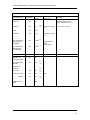
1
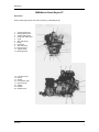
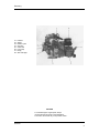
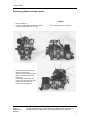
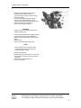
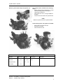
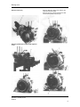
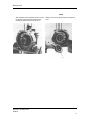
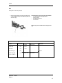
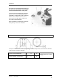
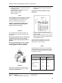
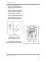
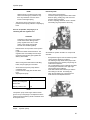
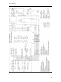
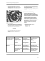
Workshop Manual
BMW D7
BMW Marine
This copy of the BMW D7 Workshop Manual has been re-created using images
computer scanned from a manual rather than original artwork.
BMW D7 Marine Engine
A four-stroke diesel engine with direct injection and open-circuit cooling system. The
Neoprene impeller of the coolant pump is driven directly from the crankshaft. Electric
starter and flywheel alternator are standard equipment. The injection system is fitted with
automatic bleeding.
Notes on Use
This workshop manual describes complete procedures for dismantling, overhaul and
assembly of the BMW D7 marine engine.
If only part of the procedure is to be carried out (e.g. small repairs or replacement of
gaskets, oilseals) the remainder can be ignored.
The relevant technical data is provided with each section. General specifications are found
on page iii.
Assembly is generally a reversal of removal procedure. Special attention, however, should
be paid to "notes on assembly".
Checking and adjustment procedures, where applicable, are to be found at the end of the
relevant section.
i
Contents
Page
Introduction
i
Summary
1
Removing cylinder head
- Preparations
- Valve mechanism
- Valves
- Cylinder head
- Cylinder
3
3
4
5
7
7
Removing gearbox
- Starter
- Reversing gear
- Bearing cover
- Hand crank mechanism
- Connecting rod
- Piston
- Fuel pump
- Timing gear cover
- Fuel regulator
- Crankshaft
- Valve lifters
- Camshaft
8
8
8
9
10
11
13
14
14
15
16
19
20
Assemble crankshaft
- Camshaft
- Crankshaft
- Fuel regulator
- Timing gear cover
- Fuel pump
- Piston
- Connecting rod
- Hand crank mechanism
- Bearing cover
- Reversing gear
- Starter
20
20
20
21
21
21
21
21
21
22
22
Assemble cylinder head
- Cylinder
- Cylinder head
- Valves
- Valve mechanism
- Hoses & pipes
22
22
23
23
23
23
Adjust:
- Valve clearance - valve timing
- Decompression lever
- Automatic decompression
24
24
25
26
Page
Fuel System
Remove, adjust:
- Injection valve
- Injection pump
- Engine speed
Check:
- Injection pump
- Injection valve
- Fuel pump
27
27
29
31
32
32
32
Air filter
33
Electrical system
- Wiring diagram
- Generator
- Starter motor
34
34
35
39
Water Pump
40
General
ii
Technical data
Capacity
Bore x stroke
Max. power
Compression ratio
Dry weight with gearbox
Gearbox reduction
Max. installation angle
280cc / 17.1 cu.in.
73 mm x 67 mm / 2.87 in x 2.64 in
4.5 kw / 6 bhp @ 3600 rpm
22 : 1
68 kg / 150 lbs
forward 2.7:1, reverse 1.9:1
o
15
Specifications
Fuel
Lubricating oil, engine
gearbox
Oil capacity, engine
gearbox
Fuel filter
Air filter
Injector
Injection pressure
Injection pump
Starter motor
Generator
Battery
Gearbox
Diesel oil, DIN 51601/USA #2
HD-API CC/CD
Hurth ATF Dexron - ZF SAE 20 W 20
2 litres / 3.5 pints UK / 4.4 pints US
0.4 litres / 0.7 pints UK / 0.85 pints US
BMW 13 32 1 328 270
BMW 13 71 1 329 269
Bosch
135 + 8 bar
Bosch PFR 1 K 70 A 343/II
Bosch 0.8 kw
14V 350W 25A
12V 60 Ah
Hurth HBW5 - ZF Bw 3
Adjustment data
Injection ends
Valve clearances, cold
o
o
11.5 - 12.5 BTDC
0.15 mm / .006 in.
Torque settings
Cylinder head nuts M 8
Nm
40
kpm
4.0
Connecting rod screws
40
4.0
Counter weight screws
22
2.2
M 6 hex nut for the mounting of the injector
Flywheel bolts M 10
Injection pump delivery valve
M 6 hex head screw for fastening bearing
cover retaining yoke on the flywheel side
Nozzle nut
10
70
40
10
1.0
7.0
4.0
1.0
85
8-9
Remarks
Use permanently elastic
sealing compound (e.g.
Atmosit) on the stud screws
in the oil space!
Oil threads and screw head
insert lightly
Oil threads and screw head
insert lightly
iii
List of Special Tools D7
BMW Part No.
Description
74 64 1 333 525
74 64 1 333 526
74 64 1 333 513
74 64 1 333 514
74 64 1 333 515
74 64 1 333 516
74 64 1 333 517
74 64 1 333 527
74 64 1 333 535
74 64 1 333 528
74 64 1 333 536
74 64 1 333 529
74 64 1 333 530
74 64 1 333 531
74 64 1 333 537
74 64 1 333 538
74 64 1 333 539
74 64 1 333 540
74 64 1 333 518
74 64 1 333 519
74 64 1 333 520
74 64 1 333 541
74 64 1 333 521
74 64 1 333 542
74 64 1 333 532
74 64 1 333 543
74 64 1 333 522
74 64 1 333 523
74 64 1 333 524
74 64 1 333 544
74 64 1 333 545
74 64 1 333 546
74 64 1 333 547
74 64 1 333 534
74 64 1 333 548
74 64 1 333 549
74 64 1 333 550
74 64 1 333 551
74 64 1 333 552
To refit ball hub
To refit crankshaft gear
Crankshaft installation tool
Puller for valve lifter shaft
Tool for crankshaft removal
Tool for camshaft needle bearing installation
Wrench for injection adjuster
Crankshaft gear puller
Tool for adjustment of injection pump
Tool for injection adjuster
Multi purpose extractor
Auxiliary wrench for cable connector
Sleeve 27 - 36 mm internal extractor
Counter support-internal extractor
Allen socket with center pin 8 mm
Allen socket with center pin 10 mm
Clamping holder to grind valve-valveseat
Allen wrench 6 mm elongated
Auxillary bush-oil seal
Punch - needle bearing camshaft
Socket 13 mm (long size)
Allen socket 6 mm
Retaining bracket for cylinder
Press-in mandrel-valve guide 7 mm Ø
Hand reamer 7 mm Ø H 7 for valve guide
Flare nut wrench 17/19 mm
Special tool for governor spring
Box wrench 10mm
Piston ring clamp
Measuring device for bumping clearance
Testing device for injection equipment
Dial gauge 1/100 mm
Torque wrench 1 - 140 NM
Guiding pin 7 mm Ø (valve reseating tool)
Handle for valve reseating tool
Piston ring pliers
Allen socket 8 mm
Valve reseating tool 42.5 mm Ø
Gudgeon pin extractor
iv
Summary
BMW Marine Diesel Engine D7
Description:
Water cooled single cylinder four stroke producing 4.5 kW (DIN) (6 Hp)
1.
2.
3.
4.
5.
6.
7.
8.
9.
10.
11.
12.
Cylinder head cover
Decompression lever
Throttle cable mount
Hand crank attachment
Cover
Sea water pump
Fitting
Hose clips
Sea water hose
Engine mounts
Cylinder head
Metering device
13.
14.
15.
16.
17.
18.
19.
20.
Fuel return hose
Injector
Air filter
Fuel injection pipe
Injection pump
Throttle
Dipstick
Oil filler screw
General
1
Summary
21.
22.
23.
24.
25.
26.
27.
28.
Exhaust
Starter
Retainer yoke
Gear box
Crankcase
Fuel pump
Fitting
Sea water pipe
CAUTION
To avoid damage to engine parts, always
use special tools as shown in the illustrations.
The tools to be used fit only in the position shown.
General
2
Cylinder Head
Removing cylinder head and cylinder
CAUTION
-
Remove air filter (1)
Loosen sea water pipe from exhaust manifold
and water pump and remove (2) + (3)
-
Disconnect fuel return hose from
injector and remove (4)
Disconnect fuel injection pipe from
injector and injection pump and
remove (5)
Remove clip of crankcase vent
hose (6), unscrew both nuts of the
rocker cover and remove the
rocker cover with gasket (7)
-
Detach
Disassemble
Remove
Cover all openings in the fuel system
Air filter, seawater hose, fuel overflow hose, cylinder head vent hose clip,
cylinder head cover with gasket, rocker shaft with rockers, pushrods
3
Cylinder Head
-
Remove rocker shaft with bushing and retainer yoke
and remove rockers (8) and (9)
Pull out both pushrods
Cylinder Head Repair Data
Dimension
D7 nominal
values
Max. allowable
wear (mm)
0.05
Rocker arms
shaft dia.
mm
18 -0.027
Rocker arm
internal dia.
mm
18
Rockaer arm
radius
mm
8
Valve seat angle
Detach
Disassemble
Remove
o
+0.024
+0.006
0.05
Remarks
After press fitting
No flats
45
Rocker shaft with rockers, pushrods
4
Cylinder Head, Timing Gear
-
Remove decompression lever from the
underside of the cylinder head (10)
Unscrew the M10 nut and unscrew stud bolt.
Remove the spring
Remove retaining pin with pointed pliers
Unscrew inner clamping sleeve on gear
segment and remove shaft and gear segment.
Remove valves & valve springs (11)
Press down the spring retainers
WARNING
Danger of injury due to spring retainers and
valve keys popping out.
-
Loosen both key halves while applying pressure
from below and remove with pointed pliers.
Remove cap and washer from under the valve
spring
Remove valve
Press out the valve guides from below
NOTE
When pressing in the new valve guides,
when parts are cold note minimum force
of 1000 N (approx 100 kp)
-
Ream the valve guides
o
Rework leaky valve seats with a 45 valve seat
cutter. Mill only enough to remove spots from
valve seats.
Reseat valves using auxiliary tool
No 74 64 1 333 539
Detach
Remove
Rework
Decompression lever handle, clamping sleeve on handle, spring shaft,
valve poppets, spring plate with valve spring, cone halves, valve guides
5
Cylinder Head
The valves should sit back as measured from the seating surface of the cylinder head, according to the
following table:
Cylinder Head
Dimension
Repair Data Valves
D7 nominal
Max. allowable
values
wear (mm)
Valve clearance
cold
mm
0.15
Intake valve stem
dia
mm
7
-0.04
-0.05
0.05
Exhaust valve
stem dia
mm
7
-0.05
-0.04
0.05
Intake valve
disc dia
mm
30.5
Exhaust valve disc
dia
mm
30.5
Valve sit back max
mm
0.70
Valve sit back min
mm
0.45
Valve guide bore
mm
7
+0.09
0
Outer diameter
mm
10
+0.023
+0.029
Valve guide bore in
cylinder head
mm
10
+0.0011
kp
100
Valve guide press
in force
Remarks
CAUTION!
Valve sit back may not be less
than 0.45 mm as otherwise the
danger exists that the valve disc
hits the piston.
0.05
The sealing surface of the
cylinder head can be reworked to
a maximum of 0.5 mm if the sit
back of
0.7 mm is exceeded due to valve
seat milling.
With the cylinder head cold.
Table: Valve sit back
6
Cylinder Head / Cylinder
Remove cylinder head and pull off cylinder (12)
The cylinder head is unusable in the following
cases:
Sealing surface fouled or damaged i.e. uneven
Clean the sealing surface and re-grind,
observing the tolerances
Valve seats worn out or no longer suitable for
re-facing.
Cracks in the valve seats in the cylinder head
NOTE
Measure cylinder bore with a cylinder indicator
In the following cases, the cylinder is unusable:
-
Cylinder
Bore dia
Dimension
mm
Roughness Ra
Oversizes
Seize marks are found in the bore
Scratches are present
Wear exceeds 0.15 mm
Repair Data Cylinder
D7 nominal
Max. allowable
values
wear (mm)
73 + 0.01
Remarks
0.15
1.0 – 1.2
mm
+1
Remove Unusability of cylinder head/cylinder
Detach Cylinder head, cylinder
7
Bearing cover
Remove starter (13)
-
Remove attaching clamp of the cable to the
stator and remove starter
Remove the four cyclinder screws M 10 and
remove the flywheel (15) and (16)
Remove gearbox (14) complete with flywheel
cover.
Remove bearing cover
Detach
8
Bearing cover
NOTE
-
After loosening the four M6 hex screws, remove
the bearing cover with locking plate and the
sealing ring located on the inner face (17)
Bearing cover can be replaced when the engine is
cold
Remove bearing cover
Detach
9
Cover to timing gear cover / timing gear cover / hand cranking device
-
Remove screws from cover of timing
gear cover and take off the cover (18)
-
Remove hand crank mechanism (19)
with extractor tool No 666 332 00
Detach Cover of timing gear cover, hand crank device, dipstick, cover on engine bottom,
Remove connecting rod
10
Dipstick / cover on engine bottom / connecting rod
-
Turn the engine on to the flywheel side (23) and
remove dipstick (24)
-
Remove cover and O-ring from crankcase on
the engine bottom (25).
-
Unscrew the two connecting rod screws (26).
Take out connecting rod cap with oil pick-up
(27) from below and piston and connecting rod
(28) from top.
Detach
Remove
Dipstick / cover on engine bottom / connecting rod
11
Table: Repair data for connecting rod and connecting rod bearing
Repair Data for con-rod bearing and con-rod
Con-rod bearing
Dimension
D7 nominal
values
Max. allowable
wear (mm)
Remarks
Minimum bearing play =
0.040-0.076mm when new
Outer dia
mm
46
Inner dia
mm
42
Width
mm
26.5
Undersize
mm
41.5
Con-rod bearing
wall thickness
normal(W)
mm
1.998
Con-rod bearing
wall thickness
oversize(WU)
mm
2.248
+0.02
Gudgeon pin
bushing bore dia
mm
28
+0.013
Con-rod bearing
bore dia
mm
46
+0.010
+0.016
-0.026
see table on page
17
max wear to 0.15mm
see table on page
17
+0.02
Total play after
wear:
max 0.15mm
Con-rod
Gudgeon pin
bushing:
outer dia
mm
28
inner dia – loose
mm
25
- installed
mm
25
0
-0.006
+0.048
+0.035
+0.082
+0.068
0.20
+0.020
+0.007
Thread con-rod
bolts
M8
12
Piston
Note
Heat piston to remove piston pin
-
Remove the gudgeon pin snap rings and press
out the gudgeon pin by hand while the parts are
still warm (29).
In the following cases, the piston is unusable:
ring land between the rings broken
piston scuffed
ring groove worn out
and cracked
Piston rings are unusable when the gap is too
big
Repair Data
Piston
Dimension
D7 nominal
values
Piston dia
mm
72.96
Oversize
mm
+1.00
Overall length
mm
Piston ring gap
(new condition)
mm
Unscrew
Detach
Max. allowable
wear (mm)
Remarks
82mm
0.25 – 0.4
Up to 2.00
Piston
13
Fuel pump / timing gear cover
-
Remove fuel pump (29a)
-
Remove pump plunger (29b)
-
Unscrew the three M16 hex nuts and
remove timing gear cover (29c)
Detach Fuel pump, pump plunger, timing gear cover
Remove
14
Fuel regulator, gear on crankshaft
-
Bring engine into the horizontal position, as
shown in Fig (29d)
Remove gear from crankshaft using extractor
tool (29k)
Loosen M6 hex nut (29f) on the regulator lever
and pull out locking pin with pointed pliers
Unscrew both M10 hex nuts (29e) from
regulator shaft.
Remove regulator shaft together with round
nut, spring washer, sealing ring and friction
disc.
Unscrew M8 hex nut. Withdraw eccentric bolt
with cap plate and sealing ring
Loosen M20 hex nut. Remove start filling (29h)
with sealing ring.
Pull out clamping sleeve, using pointed pliers.
Withdraw regulator lever with regulator spring
(29i)
Turn engine on flywheel side.
Repair Data for Regulator Spring Washers
Maximum rpm
3600/160
No of balls
4
Regulator Spring BMW Part No
13 41 1 329 652
Wire Dia
2.6
Remove Regulator lever with regulator spring
15
Ball sleeve / Crankshaft
-
Remove ball sleeve with sliding disc taking care
that no balls fall out (30)
Ball hub and spacer washer (31) remain on
crankshaft. Detach these parts only when
removing the crankshaft.
-
Turn the engine block into the horizontal position.
Removing the crankshaft
NOTE
It is essential that all plastic parts such as oil filler
cover and cold start cover are removed
-
Heat the crankcase on a heating plate to between
o
80 and 100 C (32)
Press out the crankshaft with extractor tool (33)
74 64 1 333 515
Press off the roller bearing on timing side (33a)
Press off straight roller bearing together with
spacer washer and drive dog hub (34)
Remove Ball sleeve, crankshaft
16
Crankshaft
The outer race of the straight roller bearing on
the timing gear side remains in the crankcase
and can be removed with the aid of a press
In order to remove the bearing rings which have
been shrunk on to the crankshaft (35) heat the
crankshaft on a heating plate or with a sufficiently
o
large gas burner rapidly to about 70 to 80 C
After removal of the M8 cylinder head screws,
remove the counterweights (36).
Set the crankshaft on a solid support and loosen
bearing race by a blow to the crankshaft.
Repair Data for Crankshaft Crank Pins
Crank pins must not become convex upon regrinding. A concave shape of from 0.01 to 0.02 mm in diameter
in the mid portion of length is allowable.
Crank pin nominal diameter (D)
42
-0.060
+0.074
mm
Crank pin diameter undersize (DU)
41.5
-0.060
-0.074
mm
Total play when worn out max
0.15mm
Remove Crankshaft
17
Table: Repair data for crankshaft
Repair Data for Crankshaft
Crankshaft
Crank pin dia
Dimension
mm
End float
D7 nominal
values
42.0
-0.060
-0.070
Max. allowable
wear (mm)
Remarks
Total play 0.15 max
Max allowable crank pin
out-of-round 0.05mm
Grinding finish see
page 17
Hardness at least
48 RC
0.3
+0.068
0
Crankshaft crank
pin width
mm
33.0
Radii on crank pin
mm
3.0
Hardness of crank
pin
RC
50-55
Depth of hardening
of crank pin
mm
1.1-1.5
Diameter of ball
hub (regulator)
mm
29.0
+0.021
0
Diameter of ball
sleeve
mm
28.0
-0.020
-0.041
Diameter of gear
on crankshaft
mm
22.0
+0.048
+0.035
Regrinding of
crankpin
mm
0.5
Axial play
mm
0.3-0.4
18
Valve lifters and camshaft
-
Remove the plastic plug from the side of
the engine block (37)
Unscrew the M8 set screw (38) with a 4
mm Allen key and remove together with
plug
CAUTION
When removing the camshaft, lift
off both rockers from the camshaft
to prevent damage by the cam
lobes
-
Pull out valve rocker shaft with the aid of
extractor tool No 74 64 1 333 514 (39)
-
Remove valve rockers together with
washer (39b, 39c)
Replace valve rockers if worn.
Withdraw camshaft
Press roller bearing off the camshaft
Rotate crankshaft so that the needle
bearing becomes accessible.
A damaged camshaft needle bearing can
be removed from the crankcase with drift
punch No 74 64 1 333 519.
-
Remove
Valve lifter shaft, valve lifters, camshaft, roller bearing
19
Crankshaft
Camshaft
Reassembly of the engine parts is carried out in the reverse order.
Installing the crankshaft
NOTE
The tooth gear on the camshaft is marked with the
letter “L”. This indicates the direction of rotation of
the engine as viewed from the front.
-
-
CAUTION
Drive in the rear camshaft bearing using the
assembly punch No 74 64 1 333 516.
Install the camshaft.
Screw in the set screw and replace the plastic
plug.
Insert the valve lifter shaft and tighten, so that
the valve lifters show a minimum of axial play
but are still free to move on the valve lifter shaft.
NOTE
The crankshaft bearing is asymmetrical.
The correct position is that shown in the
illustration (41). The large rounding must
be placed towards the outside, to ensure
sufficient lubrication.
-
Take care that the thrust washer is
placed between the valve lifters and the
crankcase to prevent the valve lifters
from wearing into the aluminium case.
Push the crankshaft with bearing into the
heated crankcase from the flywheel side, until it
reaches the stop of the special tool.
CAUTION
When installing the crankshaft, make
sure that the axial play between the
crankshaft and crankcase is between
about 0.2 and 0.4 mm.
-
Install Camshaft, Valve lifter shaft, valve lifters
Attach the counterweights, tightening the bolts
to a torque of 2.2 kg/m (16 lb/ft)
Heat the inner race of the roller bearing to
o
between 70 and 80 C and mount on the
crankshaft.
Place the retainer ring on the outer bearing
race.
Push inner straight roller bearing onto the
crankshaft together with spacer washer and
drive dog hub.
o
Heat the crankcase to between 100 and 150 C
on a heating plate.
Push the outer race of the bearing on the
flywheel side onto the crankshaft and screw it
on using special tool No 74 64 1 333 513
Replace all plastic parts such as oil filter cover
and cold start cover
Turn the engine back onto flywheel side and
place ball sleeve with sliding disc into position.
Take care that the balls are inserted correctly.
Crankshaft, ball sleeve
20
Fuel Regulator / Gear on the Crankshaft
Timing gear cover / Fuel pump
-
Set the engine block into the horizontal position
Insert regulator lever and regulator spring
Insert clamping sleeve into the regulating spring
with pointed pliers
Install start filling sealing ring and tighten M20
hex nut
Install eccentric bolt with cap, plate and sealing
ring.
Insert regulator shaft and tighten both M10 hex
nuts.
Insert stop pin into the regulator lever and
tighten hex nut.
Connecting Rod
Crankcase cover / dipstick / bearing cover
Install connecting rod in such a manner that the
scoop is filled through the scoop opening when
dipping into the lubricating oil. Scoop opening
must point in running direction. The lubricating
system is based on the centrifugal principle.
CAUTION
Set the cylinder slowly with great care onto the
piston so that no piston ring is broken or damaged.
Observe that the opening in the combustion
chamber located in the piston crown points towards
the flywheel side.
Install gear on the crankshaft
-
-
-
Before assembly, heat the cog for the
crankshaft on a heating plate or in an oil bath to
o
approx 80 C and assemble with tool No 74 64 1
333 526
When mounting the cog onto the crankshaft,
take care that the marking on the cog opposite
the key groove points to the outside
-
Install crankcase cover with seal into the
underside of the engine block
Insert dipstick
Turn engine block to the horizontal
Assemble starting crank mechanism with
extractor tool No 666 332 00
Screw on the cover to the timing gear cover
Mount bearing cover
Turn engine block onto flywheel side.
When mounting the timing gear cover, adjust the
cog on the camshaft and the cog on the
crankshaft so that their markings are opposite
each other.
CAUTION
In order to avoid damage to the bearing cover during
assembly, use auxiliary bushing No 74 64 1 333 518
Check upper dead center and overlapping.
-
Mount the timing gear gear cover with light taps
of a hammer and tighten both M16 hex nuts
NOTE
It is imperative that copper washers be used for the
timing cover screws
-
-
Insert pump tappet and mount fuel feed pump
Before assembling the pistons, heat them on a
hot plate. Insert gudgeon pin and the gudgeon
circlips.
Turn the piston ring gaps of the two piston rings
o
and of the oil scavenge ring 120 to each other
Lightly oil the threads and the screw head
inserts of the connecting rod parts
Insert the connecting rod bearing half with the
hole into the connecting rod cap
Insert the connecting rod bearing half without
the hole into the connecting rod
Assemble the connecting rod. Tighten the
connecting rod screws with torque wrench and
6mm socket No 74 64 1 333 541 to torque of 40
Nm (4 kpm)
Install Regulator lever, regulator spring
Mount Regulator shaft, cog on crankshaft
Fill the groove in the bearing cover between
packing washer and dust lip with ball bearing
grease
Mount the sealing ring on the inside of the
holder, onto the holder with grease in order to
prevent slipping during assembly.
Insert the thrust ring into the dry bushing with
the graphite coated side towards the outside.
Mount the cog onto the camshaft without
Woodruff key and tighten
NOTE
The marking of the cog on the camshaft must align
with the Woodruff key groove.
-
Coat the sliding surface of the dry bushing with
molykote grease
Insert the cog with needle bearing into the dry
bushing
Fill the housing with approx 100g of hot bearing
grease e.g. “Calypsol WDT” or equivalent
quality and assemble with gasket.
Timing gear cover, connecting rod
Cover on crankcase, starting crank device,
cog on camshaft
21
Flywheel / Stator / Reversing Gear / Starter / Cylinder head
-
Fasten the stator in the crankcase and screw on
the attaching clamp
Install the flywheel. Tightening torque of the
flywheel screws is 7.0 kpm
Attach the reversing gear
Attach the starter
-
Adjust the gap with a corresponding cylinder
foot gasket
The gasket set contains gaskets of various
thicknesses.
NOTE
When installing the cylinder head pay close attention
to the following points. It is imperative that a new
cylinder head gasket be used and pay close
attention to valve sit back and tightness
Tightness is checked by filling fuel into the
intake or exhaust channel. If nothing leaks
through, the valve seat is tight.
CAUTION
Do not damage the rubber sealing rings for the
decompression lever, resp. decompression shaft
and stop pin
After replacing cylinder, piston, connecting rod,
crankshaft or crankcase, measure the gap
between cylinder and piston upper surface at
TDC (42).
-
Mount the completely assembled cylinder head
onto the cylinder
Fasten the cylinder head with the aid of socket
wrench No 6425 evenly and crosswise with the
required tightening torque.
Tightening torque of the M8 hex nut on studs
(tension rod) for the fastening of cylinder and
cylinder head – 35 Nm (3.5 kpm)
Use the measuring bridge No 74 64 1 333 544
and clamping piece No 74 64 1 333 546 with
measuring gauge, for measuring the gap.
NOTE
Oil threads lightly. However, do not use molykote.
Seal locking screws in the oil space of the cylinder
head with a permanently elastic sealing compound
(e.g. Atmosit or similar)
Repair Data
CAUTION
Cylinder Head
Dimension
D7 nominal
values
Piston gap (A)
mm
0.55 – 0.65
Cylinder head (b)
gasket
mm
1.50
Cylinder shim
mm
0.1/0.2
If the gap is too small piston, cylinder head and
valves may be damaged. If the gap is too large,
the engine loses performance.
Assemble Flywheel
Test
Valve seat tightness, piston gap
Cylinder head
22
Cylinder head / Injection pipe / Leak-off-line / Water pump / Water hose / Air filter
-
Press in valve guides from underneath
Insert valves
Insert valve springs with cap and washer
Insert spring plate
Insert both valve keys, while applying counter
pressure to the valve
Insert shaft with gear segment and screw in
internal clamping sleeve.
Slide handle with ring onto the shaft and screw in
external clamping sleeve.
Insert push rods
Insert rocker arms and assemble rocker shaft
with bushing and retaining plate (43)
NOTE
Check that the rocker arms are free to move
-
Adjust valve clearance
Fasten cylinder head cover and vent hose clamp
with both nuts
Fasten injection pipe to the injection pump and to
the injector
Attach leak-off-line hose to the injector
Install water pump
Fasten water hose to the water pump and to the
exhaust manifold
Attach air filter
Assemble Valves, push rods, rocker arms, cylinder head cover.
Install
Injection pipe, leak-off-line, water hose, air filter
23
Timing gear adjustment
Adjust valve clearance and timing
The following must be carried out:
-
NOTE
Carry out the testing and adjusting when the engine
is cold.
-
Set the decompression lever to “0”
Remove cylinder head cover
Crank the engine in rotation direction until the
compression resistance can be felt
Check valve clearance between rocker arm and
valve shaft with a feeler gauge
In the case of incorrect valve clearance, loosen
the lock nut and adjust the set screw with a
screwdriver so that the feeler gauge can be
pulled through between the rocker arm and the
valve shaft with noticeable resistance after the
nut is
re-tightened
Repair Data Valves
Cylinder Head
Dimension
D7 nominal
values
Max. allowable
wear (mm)
Valve clearance
cold
mm
0.15
Intake valve stem
dia
mm
7
0.05
Exhaust valve
stem dia
mm
7
0.05
Intake valve
disc dia
mm
30.5
Exhaust valve disc
dia
mm
30.5
Valve sit back max
mm
0.70
mm
0.45
Outer diameter
mm
7
Valve guide bore in
cylinder head
mm
10
mm
10
kp
100
Remarks
CAUTION!
Valve sit back may not be less
than 0.45 mm as otherwise the
danger exists that the valve disc
hits the piston.
Valve sit back min
Valve guide bore
Valve guide press
in force
0.05
The sealing surface of the
cylinder head can be reworked to
a maximum of 0.5 mm if the sit
back of
0.7 mm is exceeded due to valve
seat milling.
With the cylinder head cold.
Adjust Valve clearance
24
Decompression lever adjustment
If the engine is not decompressed in Position “1” of
the decompression lever, adjust the decompression
screw as follows:
Crank the engine to the same position as in the
valve adjustment
Turn the decompression lever to Position “1”
After loosening the hex nut, turn the adjusting
screw to the right until the rocker arm touches
the valve shaft
From this position, turn the adjusting nut
another quarter (¼) revolution to the right and
secure by tightening the nut.
The engine is equipped with automatic
decompression.
Function:
-
If the handle is set to Position “2”, cranking the
motor automatically turns the handle further to
Position “0” (compression)
A specially designed tappet turns the
decompression shaft further with every raising
of its valve.
Extract the clamping sleeve of the gear segment on
the valve shaft with pointed pliers and dismantle the
decompression shaft with gear segment.
Installing the automatic decompression system
NOTE
The hole for the clamping sleeve in the
gear segment, viewed from the flattened
side of the shaft, lies towards the outside
of the engine.
In this arrangement, the automatic decompression is
operated by the left tappet (when looking towards
the timing gear side). The decompression handle
turns clockwise.
The length of the tappet (with collar) is adjustable.
The standard length is
147.8 – 148 mm
Adjust Automatic decompression
25
Timing gear adjustment
Correction is required in the following cases:
If the collar pan constantly engages the cog
lightly, in the case of running the engine and
zero position of the decompression lever (Shaft
moves back and forth)
In this case, shorten the tappet somewhat and
dimension “A” will become larger (see figure)
-
The decompression shaft is not rotated further
properly from position “2” of the handle
In this case, lengthen the tappet somewhat and
dimension “A” will become smaller (see figure)
Correct the position of the collar pan to the cog
(lateral distance) by a small movement of the
rocker arm shaft on the cylinder head plane.
NOTE
Choose distance “B” so that certain
functioning of the automatic system is
ensured. In the running position of the
engine (lever position “0”) the collar pan
may not touch the cog.
Fix the cog segment on to the shaft so that the
cogged area is on the upper side when the flattened
part of the shaft points upward.
Adjust Decompression lever
26
Injector
Injector check
Check injection valve for:
-
CAUTION
Function
Injection pressure (ref figure with pintle type
nozzle)
Be sure to observe a maximum of
cleanliness when working on the fuel
system
-
Remove injection pipe and leak-off-line
Loosen M6 hex nut and remove injector
from the cylinder head together with holding
bracket
NOTE
During removal and installation of the
injector, pay attention to the sealing
washer in the cylinder head
Position of the sealing disc: the side with a
recess towards the injection nozzle. The sealing
washer must seal properly.
Fuel Injection Equipment
Remarks
Injection Pump
Bosch type code
Bosch No
BMW Part No
PFE 1Q 55/19
0 414 050 996
1351 1329 656
Injector Assy
Bosch type code
Bosch No
BMW Part No
0432 297 022
1351 1329 667
Nozzle
Bosch type code
Bosch No
BMW Part No
DNO SD 21
0434 250 001
1353 1329 669
Injection pressure
135 bar
Remove
Injector
With second hole in housing
(for automatic venting)
Check
Injection system
27
Injection pump
-
Adjust the injection pressure by inserting or
removing shims at the injector spring
NOTE
A shim with a thickness of 0.1 mm
changes the pressure by approx.
15 bar
-
Injector overhaul
Extreme cleanliness is necessary during work on
injector.
-
Unscrew the screw cap and remove the injector
nozzle
Unscrew sleeve nut F (22 mm) and withdraw
injector jet G
Clean jet with correct apparatus, not with sharp
tool, wire brush or similar. All traces of carbon
should be removed.
Injector should be replaced as a complete unit if:
CAUTION
Clean the nozzle only with a
Bosch nozzle cleaning device.
Do not use hard objects as steel
brushes, wire or similar.
Carry out the cleaning and
testing of the nozzle with a
maximum of cleanliness, rinse
injector parts in clean fuel only.
Microscopically small particles
can lead to wear and
malfunction.
-
Jet needle H is damaged or eroded
Overheating of the needle and jet has occurred
(blueing)
Taper of jet needle does not seal
NOTE
A malfunctioning nozzle leads to,
amongst other things, poor combustion
(black exhaust smoke), poor
performance and overheating of the
cylinder head, piston and cylinder.
Injector operation check and adjustment
This should be carried out as completion of checking
operation of injector pump.
With special tool 74 64 1 333 545 fitted to
injector pump. See page 32
Remove
Injector nozzle
28
Injection pump
Preliminary tasks before removing the injection
pump:
The injection pump has two hose connectors and a
pipe connection. The lower connection is for the fuel
supply, the upper connection is designed for the fuel
return hose.
The start maximum fuel eccenter must be turned in
such a manner that the eccentric arm points
vertically upward before installing the injection pump.
-
-
Remove the injection pipe
Clamp off the fuel supply line
Pull off fuel return hose and fuel supply line from
the injection pump
NOTE
Set the engine throttle to the full position without
pulling the start filling lever when removing the
injection pump.
-
Remove the injection pump hex nuts and pull
out the pump
Bring the regulator lever into the center position
by slightly adjusting the position of the eccentric
shaft.
Rotate the plunger on the injection pump
The bolt must be exactly in the
middle of the groove in the pump
housing.
-
Insert the shims and carefully slide injection
pump in without shifting the regulating bushing
NOTE
Pay attention to the shims between the
pump and crankcase and the washer
in the pump tappet.
-
First install the fuel supply line, then fasten the
valve.
When installing the injection pump, rotate the
camshaft so that the injection pump tappet lies on
the camshaft basic radius (lowest position).
-
Set regulator lever with the aid of the throttle
Remove
Injection pump
29
Injection pump
NOTE
Slide the pump in to about the last 4 mm
without overcoming any resistance. Only
then may resistance occur due to the
tension of the tappet spring
Preliminary work:
-
-
This tension can be overcome by a small
pressure and the pump pushed in completely by
hand.
Clamp off the fuel supply line
Unscrew injection pump pressure valve holder.
Remove spring, sealing ring, valve cone and
pressure valve (see figure)
Screw in adjusting device No 74 64 1 333 535
with sealing ring and pressure valve body
If this is not possible, the plunger pin is
interfering with the regulator lever.
CAUTION
A fastening of the pump in this position
would cause serious damage to the
pump, regulator lever and, in some
cases, to the engine (during start,
because of a blocked regulator)
-
Determine the correct position of the injection
pump:
(1) Move the throttle in both directions. The
regulator lever must audibly reach its stops.
(2) Remove the injection pipe together with
delivery valve holder
NOTE
When moving the throttle and the start filling
button, the pump plunger must rotate
-
Screw down the injection pump after the
completed check
Connect the fuel supply line and fuel return
hose
Adjust injection pump
Set throttle into position “START”. Do not pull cold
start filler.
-
Set flywheel to approx 2.00 mm before top dead
center (observe direction of rotation)
The marking for tope dead center (OT) as well
as the degrees for the injection pump timing are
located on the flywheel
The countermarking on the crankcase is located
on the flange thread hole on the upper right
(when looking at the flywheel)
Insert dial indicator with extension pin with the
zero setting at 1.00 mm and clamp (45)
Open the fuel supply line. Fuel free from air
must flow from the adjustment device.
Injection Pump Adjustment
Injection timing –
delivery end in degrees
before TDC
11.5 – 12.5
Delivery stroke in mm
1.40
NOTE
The injection pump of this engine has the helical
groove on top of the plunger. The adjustment of the
injection timing and delivery stroke is therefore done
at the injection end.
Adjust
Injection pump
30
Injection pump
Adjustment of the delivery end:
-
-
Crank the engine in the direction of rotation until
the fuel stops to flow from the adjustment device
Slowly crank further, until the fuel just begins to
flow again
After the adjustment is completed remove the
dial indicator and install the completely
assembled delivery valve with injection pipe in
the correct sequence.
NOTE
NOTE
The number of degrees indicated on the
flywheel must correspond with the nominal
o
values (11.5 – 12.5 BTDC). If the values do
not correspond, correct with the shims
inserted under the pump.
Pressure valve body with the exterior
truned groove lies in the direction of the
pump tappet.
When screwing in the injection pipe, replace the
internal copper sealing ring and the external O-ring.
Observe tightening torque.
Basic rule:
CAUTION
More shims = delivery ends later (lower number of
degrees)
Less shims = delivery ends earlier (higher number of
degrees)
When adjusting rpm it is imperative that
a tachometer is used
In order to determine which thickness of shims must
be removed or added, rotate the flywheel to the
required number of degrees from the delivery end
already determined (dial indicator set at zero)
NOTE
The camshaft is geared down in a ratio
of 1:2. The rpm measured there must
therefore be multiplied by 2 in order to
arrive at the nominal rpm
The value shown on the dial indicator corresponds to
the thickness of the shims which must be added or
removed in order to compensate for the difference.
NOTE
Repeat the procedure after the adjustment
as a double-check
-
Set the delivery stroke at the correctly set
delivery stop.
Set the dial to zero.
Rotate the flywheel against the direction of
rotation until the dial indicator indicates the
delivery stroke value.
Hold the flywheel at this position.
At this point fuel must just start flowing out of the
leak-off-line. If this does not occur, loosen the start
filling lock nut with wrench No 74 64 1 333 517 and
carefully turn the eccentric shaft with wrench No 74
64 1 333 528 until the fuel begins to flow.
-
-
In order to adjust the rpm, remove the plastic
plug and loosen the retaining nut
Turn the eccentric shaft, recognisable from the
outside only as a set screw, with the aid of a
screwdriver, until the desired rpm is reached
Move the throttle in the direction of STOP briefly
after each adjustment of the eccentric shaft and
then bring the throttle to the full throttle stop
position
Check injection pump and injection valve for
correct function (46)
After having correctly adjusted the rpm, fasten
the retaining nut again and insert the plastic
plug
Preliminary work for the functional check of the
injection pump and injection valve
Subsequently tighten the locknut again
NOTE
-
Remove injection pipe
-
Vent the engine correctly
As a check, also repeat this adjustment.
Adjust
Injection pump
Adjust
Engine speed
31
Injection pump / Injector
-
NOTE
WARNING
Carry out the check with the throttle in the
fully open position and with the starting
filling not pulled.
Danger of injury due to the fuel jet
After installing the testing device No
74 64 1 333 545 of which the connections at
the sides must be closed off, crank the engine
by hand until the pressure gauge shows a
pressure of 300-350 bar
WARNING
Danger of Injury
-
Venting Injection pump
Fuel pump
As the engine has automatic fuel system venting, the
necessity for a manual venting does not apply, as
the trapped air in the injection pump escapes
through the return line during the filling of the pump
with fuel.
Due to the pulsating of the feed pump, the restrictor
causes a constant flow of fuel in the injection pump.
Possible gas bubbles are automatically drawn off,
thereby service interruptions resp. interferences are
prevented.
NOTE
Stop cranking and watch whether the pressure
is maintained. If the pointer falls back, and if the
pump does not maintain a pressure of 250 bar
either, the injection pump is defective
In the case of possible service
interferences and after longer periods of
engine standstill check the functioning of
the vent valve.
NOTE
During the testing, the injection valve can
be connected to the testing device in
place of a blind plug.
WARNING
Danger of Injury
-
If this is not the case, stop the engine and
unscrew the vent valve
-
-
When cranking the engine by hand, watch the
injection pressure on the pressure gauge and
the function of the injector
Crank the engine with the handcrank resp.
starter and remove the vent valve at entry to the
fuel tank
Fuel must pulse from the fuel line
-
Clean the valve with fuel and compressed air,
resp. replace the valve
When cleaning the fuel supply pump, unscrew
cover and remove filter.
Clean the fuel filter, especially under protruding
corners of the cover
Insert the filter again, fasten cover.
Correct function “a”
Incorrect function “b”
Check
Injection pump, injector
Check
Clean
Fuel jet, venting
Fuel pump
32
Air filter
Cleaning the air filter
-
Loosen clips. Remove filter element.
Remove sealing ring from cover and clean
groove
Install new sealing ring and filter element.
NOTE
Never use an old filter element
-
Clean air intake openings and pipe in the filter
NOTE
Premature engine wear occurs if
unfiltered or badly filtered air is drawn
in through a badly maintained air filter
Clean
Air filter
33
Wiring diagram
34
Generator and generating equipment
Preparation
Remove starter motor
Detach gearbox/clutch cover assembly
Remove clutch
Remove flywheel
Rotor Removal
Extract spring clip A from flywheel magnet by
inserting snip-nosed pliers into cut-outs provided
-
Generating Equipment Removal
Disconnect leads from temperature sensor and
remove stator cable plug C from socket on
equipment carrier
Remove bolts D (13 & 19 mm), noting position
of spacers, washers and injector pipe clip (if
fitted) and remove carrier and equipment
complete from engine.
Pull magnet B from flywheel with even
movement, if necessary with suitable puller
Stator Removal
Detach plug E from stator cables with fine
implement, first marking their positions.
35
Generator and generating equipment
-
Flatten lockwasher/cable clip F (renew on
assembly), securing stator cable to bearing
housing (SW 13)
Remove bolts G (7 mm) and lift off stator
-
Lay stator harness close to bearing housing, to
avoid contact with flywheel
Bend tags of stator cable end slightly to ensure
firm fit before fitting to plug. Note fitted positions
of cables.
Operation check and fault-finding
-
Notes on Assembly
Grip magnet (rotor) firmly by hand and carefully
place in flywheel, taking care to avoid jamming
by lowering unevenly. If necessary, tap magnet
with judicious use of soft-faced hammer
-
Check that cable insulation is in order
Examine stator windings for possible damage
Check all connections for corrosion and ensure
that connections are firm
The generator generates current without
mechanical contacts and has no bearings.
Faults, therefore, generally arise from shortcircuits, loose or wrong connections in electrical
circuit of boat.
When faults occur, first check circuit, then
operation of generator in situ (see wiring
diagram)
Required for testing are:
Voltmeters 0-15 DC, 0-250 AC
Ammeter 0-40
Test/amp 12V
CAUTION
Do not hit magnet directly with a metal tool,
or heat flywheel (loss of magnetism can
result)
Fault
Possible Cause
Check
Remedy
Control lamp remains lit
after starting engine
Faulty impulse
transmitter. Faukts in
boat circuit (e.g. short
circuits)
Check impulse
transmitter (see section
checking procedure 1)
Check boat circuit for
faults.
Renew impulse
transmitter
No charge
Check charge (see
checking procedure 2)
See 2 (this table)
Defective control unit
Check voltage (see
checking procedure 3)
Depending on result
renew control unit and/or
generator
Faulty generator (control
unit is usually also
defective)
Check voltage (see
checking procedure 3)
Renew generator rotor
and/or stator. Possibly
renew control unit.
No charge
36
Generator and generating equipment
Checking Procedure 1 – Impulse Transmitter
-
Thin red lead of impulse transmitter earths control
lamp when engine is stationery. When charge from
control unit passes through transmitter, this earth is
interrupted.
-
When no or insufficient charge are shown,
control unit and/or generator are defective
For further fault location, voltage between each
of the 2 black leads, red lead and generator
should be checked.
To check:
Disconnect thin red lead from boat circuit and
connect 12V testlamp connected to B+ (charge
lead)
With the engine stationary, testlamp should
light, and at 1150 rpm extinguish
If the lamp does not extinguish, impulse
transmitter is defective and should be renewed,
or generator is not charging.
Checking Procedure 2 – Charge Current
Charge current passes from control unit (white lead)
through implulse transmitter (black lead – thick red
lead) to B+ (connection 30)
To check:
With engine stationary, disconnect thick red
cable from boat circuit and interpose 0-40 Amp
ammeter
Start engine, switch one or two items of
electrical equipment on (to load battery)
Checking Procedure 3 – Voltage Check
(without load)
This check enables generator to be checked
independently of control unit and battery
With the engine stationery, disconnect control
unit from generator (2 black, red lead from 4
pole plug)
Connect one black lead and red lead to 250V
voltmeter, ensuring remaining black lead cannot
earth
Start engine, set to maximum speed and
compare reading with that specified (see
diagram)
Repeat test with second lead
If reading is correct, generator is in order and
charging fault lies with control unit or boat
circuit.
-
37
Generator and generating equipment
-
If reading is not adequate, whereby reading of
leads 1 and 2 are different, there are 2
possibilities:
- when both leads lie below the correct reading,
rotor magnetism is inadequate and rotor should
be replaced
- when only one lead shows a low reading, a fault
in the stator windings is indicated and the stator
should be renewed.
38
Starter Motor
Starter Motor Removal
-
Disconnect cables A from solenoid
(connector 19mm) and remove
insulation B
Remove fixing nuts C (19mm) and
detach earth strap D from upper stud
Lift off starter motor
When faulty renew.
39
Water pump
Service Instructions
A.
Disassembly
B.
Assembly
-
Remove cover screws, cover and gasket
Press out impeller with 2 screwdrivers
After removing the cam, remove residual traces
of sealing compound from cam and pump
housing
Remove lip seal and O-ring
Remove bearing assembly circlip
Remove the shaft with ball bearing by pressing
in the impeller side of the shaft
Press off the ball bearings from the shaft. Do
not press the ball bearings over the sealing
surface of the shaft
-
Press the ball bearings on to the shaft. Do NOT
press the ball bearings over the sealing surface
of the shaft
Press the shaft with ball bearings into the pump
housing and fit the circlip and sealing plates (11)
Assemble O-ring and sealing plate with the
opening towards the impeller
Fasten the cam, before doing so, apply sealing
compound to cam and screw to prevent leakage
Lubricate the impeller and fit it with a rotating
movement in the intended direction of impeller
rotation
Fit a new gasket before mounting the cover
-
-
Weight and Dimensions
Type:
Dimension B
Weight
F35B-8
12.5
0.5kg
Performance Table F35B-8 Impeller Neoprene
2
Kp/cm
0.3
0.6
1.0
500 rpm
kW
l/min
700 rpm
kW
l/min
900 rpm
kW
l/min
1400 rpm
kW
l/min
2000 rpm
kW
l/min
2500 rpm
kW
l/min
0.06
0.06
0.06
0.06
0.09
0.09
0.09
0.09
0.09
0.13
0.13
0.13
0.18
0.18
0.18
0.18
0.18
0.18
3.6
3.4
2.7
5.2
4.6
4.0
6.8
6.2
5.6
11.2
10.6
9.2
16.0
15.8
13.6
20.5
19.6
17.0
Performance stated is for new pumps and water at room temperature
40
Water pump
Waterpump
1.
2.
3.
4.
5.
6.
7.
8.
9.
10.
11.
Sea water pump
Cheese head screw M4 x 8
Cover
Seal
Impeller
Cheese head screw
Washer
Cam
Straight pin
Sealing plate
Sealing ring
12.
13.
14.
15.
16.
17.
18.
19.
20.
21.
O-ring
Deep groove ball bearing
Snap ring
Shaft
Clamping sleeve
Stop screw
Hex head nut M6
Washer
Stop screw M6 x 16
O-ring
41