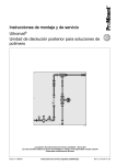
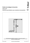
1
Modbus® RTU Serial Communication User Manual _________________________________________________________________________________ _________________________________________________________________________________ ASV Stübbe GmbH & Co.KG Hollwieser Straße 5 32602 Vlotho Germany Phone: +49 (0) 5733-799-0 Fax: +49 (0) 5733-799-5000 E-Mail: [email protected] Internet: www.asv-stuebbe.de Modbus® is a registered trademark of Schneider Electric, licensed to the Modbus Organization, Inc. Abstract This document provides generic information for ASV-Stuebbe implementing the Modbus RTU Serial Communication protocol. Information relating to specific ASV-Stübbe devices is supplied in separate user manuals. 05.11.2014 Modbus RTU 1 Contents 1. Modbus RTU Implementation ..................................................................................................... 2 2. Modbus RTU Configuration Interface ......................................................................................... 3 3. Input and Output Interface .......................................................................................................... 4 4. Modbus RTU Message Format ................................................................................................... 5 5. Modbus RTU Link Layer ............................................................................................................. 5 6. IEEE 32-bit Floating-Point Register Information ......................................................................... 5 7. Modbus General Menu Settings ................................................................................................. 5 8. Modbus RTU Function Codes Address Table............................................................................. 6 Tables Table 1-1 Table 2-1 Table 3-1 Table 4-1 Table 4-2 Table 4-3 ASV-Stuebbe Modbus devices Modbus RTU Message Formats ASV-Stuebbe Modbus device defaults PTM Modbus RTU Function Codes HFT Modbus RTU Function Codes UFM Modbus RTU Function Codes 2 4 5 5 6 7 1. Modbus RTU Implementation This implementation is designed to provide a popular data exchange format connecting these instruments to foreign master devices. The Modbus RTU allows the instrument to be a citizen on a data link shared with other devices that subscribe to the Modbus RTU RS-485 specification. Instrument Model Description PTM Pressure and temperature transmitter HFT Hydrostatic tank level sensor UFM - FLEX Ultrasonic tank level sensor Table 1-1 ASV-Stuebbe Modbus devices 05.11.2014 Modbus RTU 2 2. Modbus RTU Configuration Interface The ASV-Stuebbe Modbus uses the RS-485 (TIA-485-A) as a physical layer. There are two terminals in parallel marked with “IN” and “OUT” to connect the Modbus in a line configuration. RS-485 uses a differential balanced line over twisted pair, marked with “A” and “B” and “GND”. To connect the device use a 4 wire cable with a maximum dia. AWG22 and connect “A” and “B” with one twisted pair and a second pair with +24V and GND. It is mandatory to terminate the RS-485 bus at the end of the line. Therefore set the jumper “Bus Termination” to left and middle pin to the position “ON”. 05.11.2014 Modbus RTU 3 3. Input and Output Interface Additional to the Modbus interface, there are two SPDT relays contact and two optoelectronic isolated inputs available. The associated potential of the inputs is on the slot “PWR REL & IN”. Relay 1 and 2 could be used internally or be controlled Modbus. Example 3 shows a pump control circuit proposed with a PTM: Example 3 Note: It is recommended to ground PWR2 with PE, but it is mandatory to do this for the HFT. Button T1 “Start” and T2 “Stop” and RELAY1 is internally used from the PTM “pump control menu”. RELAY2 could be controlled from the Modbus master, for e.g. H3 and H4 shows a “service required”. To release the relays function to an external Modbus control. Set: main menu -> output -> switching type -> relay 1,2 -> modbus controlled The relay and input status is shown in the Unidisplay. The relay status is also shown via LEDs on the Modbus PCBA. 05.11.2014 Modbus RTU 4 4. Modbus RTU Message Format Table 2-1 Modbus RTU Message Formats Coding system 8 bit binary Number of data bits per character Parity Even or No Bit transfer rate 2400, 4800, 9600, 19200, 38400 Selectable Duplex Half duplex Transceiver with Failsafe Error checking CRC (cyclic redundancy check) Polynomial (CRC-16 10100000000001) Bit transfer order LSB first End of message Idle line for 3.5 or more characters (>1.75 msec for >19200 Bps). Table 2-1 ASV-Stuebbe Modbus Formats 5. Modbus RTU Link Layer The link layer includes the following properties/behaviors: Slave address recognition, Start / End of Frame detection, CRC-16 generation / checking, Transmit / receive message time-out, Buffer overflow detection, Framing error detection, 6. IEEE 32-bit Floating-Point Register Information The Modbus applications support IEEE 32-bit floating-point information for several of the function codes. 7. Modbus General Menu Settings In a Modbus RTU bus every slave uses an own unique address. Use the ASV-Stuebbe Unidisplay to set up the specific slave address. In the main menu -> basic settings -> Modbus setting -> address -> select a slave address from 1...247. 05.11.2014 Modbus RTU 5 In the main menu -> basic settings -> Modbus setting -> interface -> select a baud rate from 2400 to 38400. In the second step select even parity with one stop or no parity with two stops. Keep in mind to use the same interface settings for all Modbus member. The default settings are: Instrument Model Address Interface PTM 41 9600,8,E,1 HFT 40 9600,8,E,1 UFM - FLEX 50 9600,8,E,1 Table 3-1 ASV-Stuebbe Modbus device defaults 8. Modbus RTU Function Codes Address Table The ASV-Stuebbe Modbus RTU protocol uses a subset of the standard Modbus RTU function codes to provide access to process-related information. Several standard Modbus RTU function codes are supported. These standard function codes provide basic support for IEEE 32-bit floating point numbers and 16-bit integer register representation of instruments process data. Table 4-1 PTM Modbus RTU Function Codes Function Name Address Note: Coils, Inputs and Code starting from 1 Data type Comment Register numbers 01 Read Coil Status 0x00 -> RELAY1 0x01 -> RELAY2 Bit Read relay status 02 Read Input Status 0x00 -> INPUT1 0x01 -> INPUT2 Bit Read input status. A “TRUE” logic level on the inputs are extended to minimum 5 seconds. 03 Read Holding Registers 0x00 -> PTM Version Unsigned Integer Value = 310 -> V3.10 0x01 -> Pressure [mBar] Value = 0..10000 -> 0..10 Bar 0x0A -> Pressure [Bar] Signed Integer Signed Integer Unsigned Integer Unsigned Integer Float_ABCD 0x14 -> Temperature [°C] Float_ABCD IEEE 32-bit floating-point 0x02 -> Temperature [1/10 °C] 0x08 -> Error 0x09 -> Device ID [PTM] Value = -350..1250 -> -35,0..125,0°C TRUE -> Sensor error FALSE -> Sensor ok Value = 41 -> Device ID = 41 IEEE 32-bit floating-point 04 Read Input Registers - - - 05 Force Single Coil 0x00 -> RELAY1 0x01 -> RELAY2 Bit Write relay status, if it is released to Modbus control. main menu -> output -> switching type -> relay 1,2 -> modbus controlled value = 0x0000 -> Relay off value = 0xFF00 -> Relay on 05.11.2014 Modbus RTU 6 Table 4-2 HFT Modbus RTU Function Codes Function Name Address Note: Coils, Inputs and Code starting from 1 Data type Comment Register numbers 01 Read Coil Status 0x00 -> RELAY1 0x01 -> RELAY2 Bit Read relay status 02 Read Input Status 0x00 -> INPUT1 0x01 -> INPUT2 Bit Read input status. A “TRUE” logic level on the inputs are extended to minimum 5 seconds. 03 Read Holding Registers 0x00 -> HFT Version Unsigned Integer Value = 310 -> V3.10 0x01 -> Pressure [mBar] Value = 0..10000 -> 0..10 Bar 0x0A -> Pressure [mBar] Signed Integer Signed Integer Unsigned Integer Unsigned Integer Float_ABCD 0x0C -> Filling Level [cm] Float_ABCD IEEE 32-bit floating-point 0x0E -> Volume [l] Float_ABCD IEEE 32-bit floating-point 0x14 -> Temperature [°C] Float_ABCD IEEE 32-bit floating-point 0x02 -> Temperature [1/10 °C] 0x08 -> Error 0x09 -> Device ID [HFT] Value = -350..1250 -> -35,0..125,0°C TRUE -> Sensor error FALSE -> Sensor ok Value = 40 -> Device ID = 40 IEEE 32-bit floating-point 04 Read Input Registers - - - 05 Force Single Coil 0x00 -> RELAY1 0x01 -> RELAY2 Bit Write relay status, if it is released to Modbus control. main menu -> output -> switching type -> relay 1,2 -> modbus controlled value = 0x0000 -> Relay off value = 0xFF00 -> Relay on 05.11.2014 Modbus RTU 7 Table 4-3 UFM – FLEX Modbus RTU Function Codes Function Name Address Note: Coils, Inputs and Register numbers Code starting from 1 Data type Comment 01 Read Coil Status 0x00 -> RELAY1 0x01 -> RELAY2 Bit Read relay status 02 Read Input Status 0x00 -> INPUT1 0x01 -> INPUT2 Bit Read input status. A “TRUE” logic level on the inputs are extended to minimum 5 seconds. 03 Read Holding Registers 0x00 -> UFM Version Unsigned Integer Value = 310 -> V3.10 0x01 -> Distance [mm] Value = 0..6000 -> 0..6000 mm 0x0A -> Distance [cm] Signed Integer Signed Integer Unsigned Integer Unsigned Integer Float_ABCD 0x0C -> Filling Level [cm] Float_ABCD IEEE 32-bit floating-point 0x0E -> Volume [l] Float_ABCD IEEE 32-bit floating-point 0x14 -> Temperature [°C] Float_ABCD - 0x02 -> 0x08 -> Error 0x09 -> Device ID [UFM] TRUE -> Sensor error FALSE -> Sensor ok Value = 50 -> Device ID = 50 IEEE 32-bit floating-point 04 Read Input Registers - - - 05 Force Single Coil 0x00 -> RELAY1 0x01 -> RELAY2 Bit Write relay status, if it is released to Modbus control. main menu -> output -> switching type -> relay 1,2 -> modbus controlled value = 0x0000 -> Relay off value = 0xFF00 -> Relay on 05.11.2014 Modbus RTU 8