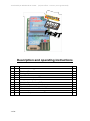
1
Translated by R.Whitehead 16-9-2011 (my best effort – accuracy is not guaranteed) Description and operating instructions 1 2 3 4 5 6 7 8 9 10 11 12 13 1 of 21 Introduction What the GPS-Logger can do Technical Data Settings Options Operation of the GPS-Logger Connection Examples Using the UniDisplay Using in Online Contest (OLC) Telemetry Operation Operation with the UniLog or Unilog 2 The SM GPS-Konverter Software Firmware update of the GPS-Logger Version History 2 2 3 4 5 6 7 10 11 17 18 20 21 Translated by R.Whitehead 16-9-2011 (my best effort – accuracy is not guaranteed) 1. Introduction The GPS-logger is a complete GPS system that was specifically developed for the needs of model construction field. It is extremely small and light, but has outstanding features and possibilities. With up to 10 Hz sampling rate and the micro-SD memory card almost unlimited recordings with high resolution and detail are possible. Telemetry via 2.4 GHz systems with a return channel is now a firm component of the GPSLogger and fully integrated. Jeti Duplex, Multiplex M-Link and Graupner HoTT are supported by the system. The GPS-Logger detects the telemetry system used by itself, there is no configuration or special firmware needed. Since in addition a barometric (air pressure) altitude sensor with high resolution is also integrated a Vario is realized in the GPS-Logger with the telemetry in use. Likewise extensive alarms are programmable, which are announced by telemetry over the respective transmitter. When operating with Multiplex M-Link all data on the sensor bus is automatically logged by the UniLog 2 and also written to the memory card MSB Data logger. The new competition format OLC, the On Line Contest, is well supported by the GPS logger. The necessary IGC file can be created directly, without any other conversion software being needed. In addition to its own readings, the GPS-Logger can also read all the data live from the UniLog via a direct cable connection and write it to the memory card. The data from the UniLog can also be transmitted to the ground via Jeti Duplex telemetry and displayed, along with the GPS-Logger‗s own data, on the JetiBox. When operating with Multiplex M-Link all the data on the sensor bus is logged automatically through the GPS-Logger and also written to the memory card. Via our UniDisplay all values measured by the GPS-Logger can be directly viewed live. Naturally all settings and alarms can also be programmed easily by UniDisplay. The presentation and interpretation of data is made in 3D in Google EarthTM. All that is required is to convert in Google Earth TM format using our free software "SM GPS Konverter" and the also free Google Earth TM standard version. The well known software LogView www.logview.info also supports our GPS-Logger. Here, the GPS data can also be converted to Google EarthTM format. In addition the values can be shown in normal curves and much more besides. Whether sailplane, aerobatics plane, helicopter, HLG or Slowflyer, the GPS-Logger can be used in almost any sector due to its small weight and compact size. Naturally the UniLog 2 is not only suitable for flying models, it can also be used in RC-boats, RC-car etc. 2. What the GPS-Logger can do • • • • 2 of 21 10Hz GPS, and so 10 readings per second particularly good data resolution Micro SD memory card almost unlimited recording and simple selection of data Data stored in plain text on the memory card subsequent processing with many programmes possible Altitude supported by additional barometric sensor Translated by R.Whitehead 16-9-2011 (my best effort – accuracy is not guaranteed) • • • • • • • • • • • • • • • Direct creation of the IGC file for On line Contest (OLC) Full telemetry support for Jeti duplex, Multiplex M-Link and Graupner HoTT, including barometric Vario Direct connection of the UniLog and UniLog is 2 possible for data capture and telemetry support Recording of all data on the Multiplex Sensor Bus in operation with M-Link Recording of receiver battery voltage Powered by the receiver battery Internal backup battery for a quick start of the GPS Start of recording by different adjustable conditions Current status is indicated by three LEDs Direct viewing of recorded values live with our UniDisplay Parameter settings over PC, UniDisplay, or telemetry is possible Fast conversion of data into 3D presentation in Google EarthTM with our free ―SM GPS Konverter‖―software. The programme is available on the Internet at www.sm-modellbau.de in the menu option Software & Updates Support by LogView software www.logview.info LogView is a very comprehensive yet easy to use evaluation programme for the PC that supports a multiplicity of different measuring devices and battery chargers from the model construction field. Free firmware updates via PC possible using our USB interface cable (the firmware file is available on the Internet at www.sm-modellbau.de in the menu option Software & Updates) Useable almost everywhere due to its compact size and low weight 3. Technical data GPS Data Rate Memory Type Recording duration Power supply Power consumption External connections Dimensions Mass GPS Module 4. Settings Options 3 of 21 1 Hz, 2 Hz, 5 Hz, 10 Hz adjustable. Micro SD or micro SDHC card (supplied with 2 GB card) With 10 Hz data rate and full utilization of approx. 200 kByte/minute storage requirement 7 days recording with 2 GB card Supplied from receiver (from 3,6 V to maximum of 8.5 V) 70 mA in full operation GPN servocable for power supply and/or telemetry COM connection for UniDisplay, UniLog, and firmware update Slot for micro SD card 32 x 21 x 11 mm 11 g without cables Sensitivity up to -165 dBm Maximum acceleration 4g (that refers only to position detection, the module is constructed using SMD techniques and can withstand substantially higher acceleration) Translated by R.Whitehead 16-9-2011 (my best effort – accuracy is not guaranteed) The settings of the GPS-Logger can be made alternatively at the PC and/or laptop with our software ―SM GPS-Konverter‖, with our UniDisplay, or over the Jeti telemetry. The settings are always backed up in parallel in the GPS-Logger and on the memory card. If new settings were written on the card with the PC software ―SM GPS-Konverter‖, these are transferred to the device at the next start. In this way it is possible to use different memory cards for different models and to receive the correct settings automatically. 5. Operation of the GPS-Logger 5.1. Installation Due to the low weight and the compact design, installation is unproblematic. Attention must be paid only to the fact that the GPS antenna is pointing up and there are no shielding materials such as metal or carbon fibre above it. Attachment with a Velcro strap on a board is sufficient and makes easy access possible to the memory card. 5.2. Memory cards As memory card practically all commercial micro SD cards with FAT16 or FAT32 file system can be used. Also SDHC cards and memory capacities over 2 GB are supported. However not all cards are equally suitable, since some cards exhibit an unfavourable behaviour with continuous storing of data. If an unsuitable card is used, the recording may run intermittently or even stop. We recommend the use only with the card provided or available as an accessory from us. The card is inserted into the slot on the back and pushed in until it clicks and is flush. The GPS-Logger does not have an ejector for the memory card, the card is simply pulled out again with the fingers. 5.3. Meaning of the LED The GPS-Logger has three coloured LEDs. After switching on a run of the three LED indicates the internal initialization. In operation there are the following signals: • orange LED shines permanently GPS ready, but still no 3D fix, i.e. GPS positioning not yet possible • green LED shines permanently GPS and 3D fix ready, i.e. GPS positioning available • orange LED flashes at the set recording rate GPS recording data, but still no 3D fix • green LED flashes at the set recording rate GPS recording data, 3D fix • red LED flashes no memory card pushed in. 4 of 21 Translated by R.Whitehead 16-9-2011 (my best effort – accuracy is not guaranteed) 5.4. Start and stop of the recording The GPS-Logger has several possibilities for starting data recording. The appropriate options can be set over our software ―SM GPS-Konverter‖, over the UniDisplay or over the Jeti telemetry. The recording of data can be started/stopped in the following way: • Manual start via telemetry: The recording is started and stopped in the Jeti Duplex or Graupner HoTT telemetry (text mode) by depressing a key at the transmitter. This start method functions even when any other start option is selected. • Automatic start with 3D-Fix: The recording begins automatically as soon as sufficient satellites are received and an initial 3D position determination made (3D-fix). • Automatic start with speed > 20 km/h: The recording begins automatically as soon as the measured speed exceeds 20 km/h for the first time. The prerequisite is that the GPS already has a 3D-fix. • Automatic start at > 20 m distance: The recording begins automatically as soon as the distance from the first measured point after switching on exceeds 20 m . The prerequisite is that the GPS already has a 3D-fix. • Start by re-inserting the memory card: Regardless of the selected start option, a recording can be started immediately on an active GPS-Logger by pulling out and re-inserting the memory card. • Automatic stop after landing: With the option ―Autostop landing‖ the recording ends automatically 10 seconds after the landing, that is if for 10 seconds the speed is less than 10 km/h. With each start of recording the GPS-Logger begins a new file. The file names are numbered consecutively and have the following format: ―2011-01-01 SM GPS Logdatei 0001.nmea ― If a recording is started and the internal clock does not provide a valid date (no GPS received or internal battery empty) then the date will be 2011-01-01 To distinguish between different firmware versions these files are always stored in a folder with this format: ―SM GPS-Logger v1.04‖ With Jeti Duplex the recording can be stopped via the JetiBox, otherwise the recording is terminated simply by interruption of the supply current. That is intended and OK. 5 of 21 Translated by R.Whitehead 16-9-2011 (my best effort – accuracy is not guaranteed) 6. Connection Examples Direct connection to any receiver. The cable is plugged directly into a free servo connection and supplies the GPSLogger with power. Since the Logger sends telemetry data on the signal line, the signal wire should in this case be removed at the receiver. Just simply remove the orange wire contact and insulate with heat shrink sleeve. Direct connection to a Telemetry Receiver as a telemetry sensor. With Jeti Duplex use the sensor input ―Ext‖. With Multiplex M-Link use the sensor input ―Sensor‖. If more M-Link compatible sensors are attached to the receiver, the GPS-Logger is the last sensor in the chain because it has no second loop connector. With Graupner HoTT receiver the telemetry port is marked ―T‖. The GPS-Logger can be connected directly to the UniLog or UniLog 2 with the leads stock no. 2720 or 2721. The UniLog is supplied with power via its current sensor, while the GPS-Logger is supplied directly from the receiver. Note: Only the three-core cables stock no. 2720 and 2721 may be used! 6 of 21 Translated by R.Whitehead 16-9-2011 (my best effort – accuracy is not guaranteed) 7. Use of the UniDisplay For connection of the GPS-Logger, firmware v1.25 or higher must used in the UniDisplay. An update for the UniDisplay can be downloaded free of charge from our homepage ( www.sm-modelbau.de ). The UniDisplay and GPS-Logger are connected with the cable provided with the display. The connector location can be seen on the top of the GPS-Logger and is labelled ―COM‖. The cable connection can be made either way round, which end is used is irrelevant. The display is powered by the GPSLogger and turns on automatically as soon as the GPS-Logger is connected. The display can be attached at any time to the GPS-Logger. The GPS Logger must therefore be supplied with power either via an attached receiver or directly with a receiver battery. Menu: First the menu is activated. The menu options can be selected with the ―plus‖ and ―Minus‖ buttons, and the appropriate item selected with ―Enter. Live data display screen 1: Here all current readings are displayed. Most values are selfexplanatory. • “Plus” starts and stops the recording. • “Minus” changes between Live/MIN/MAX values. • “Enter” changes between the Live screens 1, 2 and 3. • “Esc” changes back to the menu. Top right is the current file number. Including changes in the past, Time, date and time. “Speed” shows the genuine 3D speed, thus speed in relation to base plus vertical speed! “Hoehe” is the barometric height in relation to the starting point. “Strecke” is the travelled (flight path) distance. 7 of 21 Translated by R.Whitehead 16-9-2011 (my best effort – accuracy is not guaranteed) At “Pos” ―the current position of the GPS is seen in relation to the starting point. The air line distance and the angle in relation to north are shown. Live data display screen 2: A press of “Enter” moves to the next screen with more data. “GPS” shows the GPS altitude from sea level (asl). Also shown are latitude (Breit) and longitude (Laeng) of the current GPS position. “GZ” represents the glide ratio of the last 100 m flight path. Following is the calculated average speed on these 100 m. If no value for the glide can be indicated (model climbing), ―—― appears here. Finally the current air pressure measured by the barometric pressure sensor is shown in the last line. Live data display screen 3: A further press of “Enter” moves to the third screen with more data. ―RxSpannung‖ is the measured receiver voltage. ―Datenrate‖ shows the current recording rate. In the last line is the current status of satellites and GPS. Setup: Here the menu for all settings of the GPS-Logger appears. In the second line is the firmware version of the GPS-Logger and also the serial number. Move through the menu options with “Plus” and “Minus”, and select the appropriate point with “Enter”. Settings screen: Here the settings of the GPS-Logger are summarized. Move through the menu options with “Plus” and “Minus”, and select the appropriate point with “Enter”. The arrow then becomes a Dot and the selected value can be changed with “Plus” and “Minus”. A press on “Esc” or “Enter” stores the change. For “Start” see also 5.4. „ “Vario” and “Varioton” change the behavior only with Jeti duplex, with M-Link the transmitter takes over the tone generation in Vario operation. 8 of 21 Translated by R.Whitehead 16-9-2011 (my best effort – accuracy is not guaranteed) GPS Alarms: Alarms can be set here both with Jeti Duplex and M-Link and are announced from the transmitter module and/or the transmitter. When the arrow is in the left column and the appropriate menu option activated with “Enter”, the value of the alarm can be set. If with “Plus” or “Minus” the arrow is shifted to the right and the menu option activated with “Enter”, the alarm can be activated (“+”) or deactivated (“-“) with “Plus” or “Minus”. UniLog Alarms: Alarms can be set here in relation to operation with Jeti Duplex and the UniLog connected to the GPS-Logger. When the arrow is in the left column and the appropriate menu option activated with “Enter”, the value of the alarm can be set. If with “Plus” or “Minus” the arrow is shifted to the right and the menu option activated with “Enter”, the alarm can be activated (“+”) or deactivated (“-“) with “Plus” or “Minus”. . M-Link addresses: For transfer of GPS-Logger measured values by M-Link, addresses can be assigned here for display on Multiplex transmitters. Each address may only be assigned once to any attached M-Link sensor, including the M-Link receiver. The Bus system ceases to function with multiple assignments. If a value is not to be transmitted chose the address ―—―. This value becomes the highest permissible Address 15. 9 of 21 Translated by R.Whitehead 16-9-2011 (my best effort – accuracy is not guaranteed) 8. Using in on-line Contest (OLC) On-line Contest, OLC for short, has been for many years a popular decentralized competition type in man-carrying sport sailplanes and paragliders. Here the flights of the participants are recorded with GPS and then transferred by Internet into the OLC system. There each flight is automatically evaluated according to the Online Contest rules and the participant receives points for the flight. Starting from 2011 this system is now available for model fliers, so that they also can compare their flights with one another within their own area. Participation is completely free. Currently the flight task is a pure distance flight, however in the near future this rule will be replaced if possible by speed round a triangular course of predetermined size (naturally in pure gliding flight). More details can be found on the OLC website: http://rc.onlinecontest.org The special thing is that it is flown decentralised. Each pilot can therefore fly at any location i.e. if he has the time and desire, if the conditions appear right for it, etc. All the entered flights can be viewed constantly on line, daily detailed evaluations and ranking lists are given, as well as an annual ranking at the end of the year. Starting from firmware v1.02, the GPS-Logger can now also directly produce the IGC file which is needed for the flight evaluation in Online Contest. So no more conversion of files is necessary, just the .igc file transferred from the memory card directly into the OLC system and the flight is evaluated. This file is also signed internally by the GPS-Logger, so that the OLC server can examine this in file manipulation (this is the highest quality class for documentation). IGC mode must be activated in the settings of the GPS-Loggers. With the GPS-Konverter, entries for pilot name, model type, model name, and the competition class can also be given. These designations are stored on the memory card and entered into each IGC file. By this means, if you use a separate memory card for each model, the correct data can always automatically be transferred to the IGC file. Characteristics in the IGC mode: ● The IGC file is written in addition to the normal NMEA file on the memory card. ● The IGC file has a special file name in the IGC format. ● Recording ends automatically as soon as the GPS-Logger is stationary for 10 seconds. During these 10 seconds the green and orange LED flash alternately. ● It is also possible to start the recording with different conditions as before. 10 of 21 Translated by R.Whitehead 16-9-2011 (my best effort – accuracy is not guaranteed) 9. Telemetry Operation Apart from its functions as data logger the GPS-Logger is also a full telemetry sensor for different 2.4 GHz remote control systems. Jeti Duplex, Multiplex M-Link, and Graupner HoTT are supported. Connection to the receiver is made directly with the patch cable provided as described in section 6. The telemetry operation is similar for all supported systems, set alarms are sent over the respective systems, live data is displayed on the transmitter or on external display, and with Jeti Duplex and HoTT the GPS-Logger can also be operated from the transmitter. To help find a lost model easier there is a special off-field landing mode. After landing, and after a further 2 minutes without movement, the coordinates of the Models will automatically transfer via telemetry: ● with Jeti and HoTT it changes to the correct screen for the telemetry values. ● with M-Link, the degrees of Latitude and Longitude are displayed at the addresses for the values Vario and Speed after 5 seconds. The display changes between the before decimal value without unit and the after decimal value with the unit ―ml‖. 9.1. Telemetry operation with Jeti Duplex The GPS-Logger is a complete telemetry sensor for Jeti Duplex 2.4 GHz systems. All measured values can be transferred live to the ground and displayed on the JetiBox. The Jeti Expander cable E4 for the connection of up to 4 sensors is supported. 9.1.1. Operation of the GPS-Logger with the JetiBox After the start of transmission the JetiBox is changed to Mx < - Mx for the attached sensors. v SM GPS-Logger via Jeti Duplex Wenn beim Start ein angeschlossener UniLog SM GPS-Logger + erkannt wurde, wirdvia dasJeti auch UniLog entsprechend im Startbildschirm gemeldet. A 123.4 km / h MAX A press the on the ▼ key changes to the GPS-Logger. During initialisation you see start-up screen then the measured data is displayed. If at start-up an attached UniLog is detected, the starting screen displays accordingly. As soon as the first screen with measured data appears, the different data screens can be selected with presses of ◄ and ► keys. A pressure on the key ▲ starts the recording of 221.8 m +12.8 m / s data in the GPS-Logger, which is indicated by an audible signal. A further pressure on ▲ terminates the recording. A simultaneous long pressure on the keys ◄ and ► changes between the display of Live / MAX / MIN values. 11 of 21 Translated by R.Whitehead 16-9-2011 (my best effort – accuracy is not guaranteed) The first item on the screen is an indicator of the current active data screen and/or the status of the GPS-Logger: • the first data screen, the following screens have B, C, etc. • -- recording running, GPS has no 3D fix • * recording running, GPS has 3D fix • maximum values are indicated • minimum values are indicated < Hoehe Alarm ( AUS ) > 100 m < Hoehe Alarm ( EIN ) > < 200 m > A press of key ▼ changes to the settings. Again with the keys ◄ and ► the different screens and the desired point are selected. After a further press of key ▼ the selected value can then be changed (keys ◄ and ►). With a simultaneous pressure on ▲ and ▼ the alarm is switched On (EIN) or Off (AUS). Changed settings are only stored with the move back to the selection level with ▲. 9.1.2. Display of measured values on the JetiBox A 123.4 km / h 221.8 m B +12.8 m / s D 34.5 ° 1234.5 m NN GZ 1 : 23 Top: True 3D speed, i.e. ground speed plus vertical speed. Bottom: Barometric height from start point, current climb rate Top: Distance (flight path) 12.35 km Pos 1043 m C MAX / 48 km / h Bottom: Current GPS position in relation to start point. Top: GPS altitude over seal level (NN) Bottom: Measured glide ratio of the last 100 m flight path followed by the average speed over this 100 m 5.08v Rx Top: Receiver battery voltage 951.45 hPa Bottom: Current air pressure E 01.06.2011 12 of 21 00:14:34.5 14:55 Top: Elapsed recording time. Bottom: current date / time. Translated by R.Whitehead 16-9-2011 (my best effort – accuracy is not guaranteed) F G 46.87208 N 11.14557 123.5 ° 12 Sat 3D-Fix 10 Hz Datei 0001 Top: Current Latitude Bottom: Current Longitude, followed by current direction of travel. Top: Number of satellites, GPS status Bottom: Current recording rate, current file number. 14:55 to the GPS Logger and is read, the measured values of the If a01.06.2011 UniLog 1/2 is attached UniLog will also appear here. Values that the UniLog 1 does not supply, simply remain free and/or on 0: H 23.28 v 221.8 m 36.04 A I 1377 mAh 1750.1 Wmin Top: Drive voltage, barometric altitude from starting point Bottom: Drive current, capacity used Top: energy used 2481 rpm 839 W Bottom: rpm, drive power J 5.01 VRx 221.8 m Top: Rx voltage, barometric altitude from starting point +12.1 m / s Bottom: Vario as a numerical value K 3.61 3.65 3.66 Top: Single cells 1 - 3 3.65 0.00 0.00 Bottom: Single cells 4 – 6 L A1 - - - - °C Top: Sensor value at port A1 A2 44.9 °C Bottom: Sensor value at port A2 M A3 221.9 Km / h 1100 us -> 1100 us N 971.43 hPa internal 28.1 °C 13 of 21 Top: Sensor value at port A3 Bottom: Servo impulse at the Rx connection, servo impulse at the ESC connection Top: current air pressure Bottom: internal temperature of the UniLog. Translated by R.Whitehead 16-9-2011 (my best effort – accuracy is not guaranteed) 9.2. Telemetry operation with Multiplex M-Link The GPS-Logger is also a full telemetry sensor for the Multiplex M-Link 2.4 GHz system. The measured GPS values can be transferred live to the ground and be displayed directly on the Multiplex the Royal Pro or COCKPIT SX transmitter. The connection is made direct to the M-Link receiver with the patch cable provided as described in section 6. On the ground the data is displayed directly on the Multiplex the Royal Pro or COCKPIT SX transmitters. The settings for telemetry can be made either with the UniDisplay ( see chapter 7) or with our ―SM GPS-Konverter‖ software on a PC. Here a threshold can be set for each possible alarm, and monitoring activated. The addresses for display on the Multiplex remote control (the line that the respective value is indicated in) can also be freely selected. There is a peculiarity with the Vario settings: Since the Multiplex transmitter itself produces the Vario tone, the GPS-Logger suppresses climb values which are smaller than ―Vario threshold‖. Thus this range is hidden from the transmitter tone. Example: -―Vario threshold‖ is set to 0,5 m/s -„Vario tone is set to ―on‖ if the model rises faster than 0.5 m/s, the value is sent and the transmitters beeps if the model rises or sinks more slowly, the value 0 sent and the transmitter remains silent If the change is always required, ―Vario threshold‖ must be adjusted to 0,1 m/s and ―Vario tone‖ set to ―up/down‖. As an additional feature the UniLog 2 writes all data continuously on the Multiplex M-Link bus system and stores it in parallel with its own data on the memory card. So you can expand your M-Link sensor system to a practically infinitely large Data logger! 14 of 21 Translated by R.Whitehead 16-9-2011 (my best effort – accuracy is not guaranteed) Later the values at each individual waypoint can be evaluated directly in a 3D representation in Google EarthTM. In addition the curve in Google EarthTM can be coloured according to a selected M-Link value. 15 of 21 Translated by R.Whitehead 16-9-2011 (my best effort – accuracy is not guaranteed) 9.3. Telemetry operation with Graupner HoTT The GPS-Logger is also a full telemetry sensor for the Graupner HoTT 2.4 GHz system. The measured values can be transmitted live to the ground and displayed directly on either the Smart Box at the HoTT transmitter or directly in the display of the HoTT transmitter. The connection to the HoTT receiver is made with the Patch cable provided, between the connection on the GPS-Logger and ―T‖ on the HoTT receiver. The UniLog 2 supports both the Text Mode‖ and the ―Digital Mode‖ of the HoTT system. In both modes of operation all adjustable alarms on the GPS-Logger are indicated at the transmitter by beeps or speech output. For text mode you get there via Telemetry menu and ―Settings display‖. After screens with the Receiver data, the GPS-Logger appears in Text mode. Structure and contents are completely identical to the screens of the UniDisplay, (see chapter 7 for the UniDisplay). Here all alarms can be set, then indicated at the transmitter via beeps or speech output. For the digital mode ―GPS‖ must be activated in the Telemetry settings of the HoTT Transmitter. The GPS-Logger then sends the data in this Format, so that the transmitter can display those values in the appropriate screens. Some values from the GPS-Logger are shown differently: Climb rate in m/3s shows the number of satellites being received. Latitude and Longitude are reversed if that is recorded on the GPS-Logger memory card. 16 of 21 Translated by R.Whitehead 16-9-2011 (my best effort – accuracy is not guaranteed) 10. Operation with UniLog / UniLog 2 The GPS-Logger can be connected directly to the UniLog or UniLog 2 with the leads stock no. 2720 or 2721. This result in the following possibilities: • The recording of all measured values from the UniLog or the UniLog 2 on the memory card of the GPS-Logger synchronously with the other data. • Display of the the UniLog / UniLog2 measured values on the ground via Jeti Duplex telemetry. • Monitoring of adjustable limit values by Jeti Duplex telemetry. • Practically unlimited memory expansion for the UniLog. • Evaluation of the UniLog / UniLog 2 data at each waypoint on Google EarthTM. In order to show the battery capacity used from the UniLog 1, the port A2 must be set to ―capacity mAh‖ in the setup! 17 of 21 Translated by R.Whitehead 16-9-2011 (my best effort – accuracy is not guaranteed) 11. The “SM GPS-Konverter” software On our homepage, in Software & Updates, you will find the free software ―SM GPSKonverter‖. Using this the data is read from the GPS-Logger and converted immediately into .kmz for use in Google EarthTM. During conversion several options are available to later colour or highlight certain values in the 3D view. If you move the mouse over the buttons, you will see short help texts for the operation. 11.1. File Conversion The software opens with the ―Convert‖ tab. Here a file can be selected from the GPS-Logger and converted with adjustable options into the Google EarthTM .kmz format. If desired the resulting file can be displayed immediately in Google EarthTM. 18 of 21 Translated by R.Whitehead 16-9-2011 (my best effort – accuracy is not guaranteed) 11.2. Minimum and Maximum Values Once a file has been converted all the extremes of values can clearly be seen in the ―‖Maximum window. 11.3. GPS settings 19 of 21 Translated by R.Whitehead 16-9-2011 (my best effort – accuracy is not guaranteed) 11.4. Live Access to the GPS-Logger If the GPS-Logger is connected to a PC with the USB interface, it can be accessed via the Terminals Function of our software. The display is identical to the live operation of the UniDisplay. See also section 7. The GPS-Logger must be supplied with external power for connection to the PC! For example, directly to a 4 cell Receiver battery. 12. Firmware update of the GPS-Logger With our USB interface a firmware update can also be uploaded to the GPS-Logger. To make an update, a Windows PC with USB interface and installed driver for the USB interface is necessary. In each case of improvements in our software, an appropriate file with the update is made available free of charge on our homepage www.sm-modellbau.de within the menu item Software & Updates. The zip file must, after downloading, be first unpacked. Afterwards the exe program is started. Further steps are described directly in the software. 20 of 21 Translated by R.Whitehead 16-9-2011 (my best effort – accuracy is not guaranteed) 13. Version history Here you will find all firmware versions and the changes to the previous version. You can find the current version of your GPS-Logger firmware with our software ―SM GPSKonverter‖ or the UniDisplay. Version number 1.00 1.01 1.02 Date 10-2010 1.03 03-2011 1.04 08-2011 21 of 21 03-2011 Comment First retail version Internal test version 1. Minor bug fixes and enhancements 2. Autostart with 3D fix is now delayed for 10 s after the fix so that the GPS start height can stabilize in this time orange and green shine. 3. Support for the .igc file format added so the GPS-Logger can directly generate the files for the online Contest 9OLC) (see section *) 1. Bug fixed in the distance calculation when using M-Link telemetry. 2. 2. M-Link extended for the direct output of the values from a connected UniLog, in addition maximum speed and maximum altitude available as a separate sensor value. 1. Telemetry with Graupner HoTT added. 2. Adjustment to M-Link data logging for receiver firmware 1.20 3. The M-Link value ―Address‖ is now giving he direction to the model instead of flight direction. 4. With M-Link the threshold and tones for climbing are rethought, undesired values are suppressed to stop the sounding of tones from the transmitter. 5. Jeti telemetry now supports the Jeti Expander E4. 6. The .igc filename was changed to the .igc defaults. 7. Autostop option inserted: terminates recording 10 s after the landing. 8. Recording can arbitrarily be started again after stopping (3D-Fix Start goes only one time). 9. Off-field landing mode: after landing and after 2 minutes without movement the coordinates of the model are transferred over telemetry Jeti and HoTT are changed to the correct screen with M-Link, Latitude and Longitude are dispalayed in the addresses Vario and Speed in 5 seconds. 10. Min. and max. values of the current measurements can be called up on UniDisplay, Jeti and HoTT. 11. Adjustment for data transfer from the UniLog 2