1
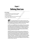
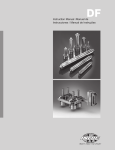
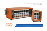
MICROCOM®
I Temperature Controller
Instruction Manual
MICROCOM® TEMPERATURE CONTROLLER
INSTRUCTION MANUAL
TABLE OF CONTENTS
1 INTRODUCTION 1.1 Main Function Pg. 2
1.2 Controller Specifications Pg. 2
1.3 Technical Features Pg. 2
1.3.1 Temperature MeasurementPg. 2
1.3.2 Temperature ControlPg. 2
1.3.3 Power Output Pg. 3
1.3.4 Other FunctionsPg. 3
2 OPERATION
2.1 Requirements for Installation and Operation
Pg. 4
2.2 Safety Requirements Pg. 4
2.3 Instructions for InstallationPg. 4
2.4 Initial Start Up Pg. 4
2.5 Controller Operating ModePg. 5
2.5.1 DescriptionPg. 5
2.5.2 Standby DisplayPg. 5
2.5.3 “Click & Rotate” Switch Operating Mode
Pg. 5
2.5.4 “Click & Rotate” Switch Locking Procedure
Pg. 6
2.5.5 Alarms DescriptionPg. 6
2.5.6 Operator Interface MenuPg. 6
2.6
Main MenuPg. 7
2.6.1 Configuration Menu 1Pg. 8
2.6.2 Configuration Menu 2Pg. 9
3 TROUBLE SHOOTING
3.1 Trouble ShootingPg. 11
3.1.1 Faults Table Pg. 11
4 WIRING SCHEMATICS & PLUG DIAGRAMS
4.1
Diagram LabelPg. 12
4.2
1 & 2 Zone EnclosuresPg. 12
4.34 Zone Enclosures Utilizing 1614-BRA
Pg. 13
4.4
6 Zone/8 Zone Enclosures Utilizing 3214-BRA
Pg. 14
4.5
12 Zone Enclosures Utilizing 4814-BRA
Pg. 15
5 WARRANTY
5.1
General Terms & Conditions of Sale
Pg. 16
6 CONTACT
6.1 Global Service Contacts
Pg. 18
6.2 Global OfficesPg. 19
www.incoe.com
©INCOE® CORPORATION 3/2011
Pg. 1
MICROCOM® TEMPERATURE CONTROLLER
INSTRUCTION MANUAL
INTRODUCTION
1
1.1 MAIN FUNCTION:
The MICROCOM® temperature controller is
designed to control hot runner systems.
• Broken Thermocouple detection automatically
switches to manual mode by applying the
last stored percentage of power to the heater
(adjustable through software).
1.2 CONTROLLER SPECIFICATIONS:
• High and Low alarm.
• INPUT POWER: 230 VAC single phase.
1.3.2 TEMPERATURE CONTROL:
• INPUT POWER RANGE: 207 VAC to 253 VAC.
There are 2 control modes :
• MAXIMUM OUTPUT POWER: 3600W.
(15 Amps).
• FREQUENCY: 60Hz / 50Hz.
A label is affixed to the cabinet indicating:
AUTOMATIC MODE (closed loop):
This is a self-tuning PID control unit. The controller
continuously monitors the behavior of the heater
which it is connected to. The controller adapts its
output to the heater by automatically defining the
P.ID. parameters.
MANUAL MODE (open loop):
In this mode, the controller sends the percentage
of power stored in memory to the manual set
point (default value: 20%). Note that this value can
only be modified in the standby display. When
the controller is in MANUAL mode, high and low
alarms are no longer active. The same is true for
the SoftStart function.
START UP PHASE (“SoftStart phase”):
1.3 TECHNICAL FEATURES:
1.3.1 TEMPERATURE MEASUREMENT:
• Thermocouple type J (“J” display) or type K
(“nI” display), grounded or ungrounded, with
automatic cold junction compensation
(selection of the thermocouple in the
configuration menu).
• Sampling rate, 83 ms @ 60 Hz or 10 ms @ 50Hz.
• Accuracy +/- 0.5% over the range 32 to 932 °F
(0 - 500°C).
• °F or °C scale (user select in the
configuration menu).
• Reversed thermocouple detection (no power to
the heater, 0% output).
Pg. 2
© INCOE® CORPORATION 4/2010
This phase is designed to avoid cold start failures
and extend the life of the heating element(s). It
eliminates the thermal shock during the transition
from cold to hot.
This phase also removes any moisture that
may have collected in the heating element(s)
by applying low power to the heater or by
progressively increasing power to the heater.
There are 2 types of “SoftStart phases”.
• RAMP DURATION: Heating with maximum power limited to15% for a 5-minute period or
up to a maximum temperature of 212°F (100°C).
• RAMP RATE: Applying a temperature rate
expressed in °F / min ° (or °C / min ) up to the
user setpoint.
www.incoe.com
MICROCOM® TEMPERATURE CONTROLLER
INSTRUCTION MANUAL
INTRODUCTION
Both ramp types can be activated to the
following conditions:
• If the unit is in automatic mode during the
start-up sequence.
• If the unit switches from manual to
automatic mode.
1.3.3 POWER OUTPUT:
• Power output via 15 amp TRIAC (BTA24 800V).
• Double protection of the load via fuse
(Ref : FA15 or ABC-15).
• Protection against over voltages (overvoltage
switch calibrated to 275V).
• Phase angle or zero crossing mode (User
selectable in configuration mode). This
choice is only valid during the control phase.
During SoftStart, the controller remains in
“phase angle” mode for whichever power
mode is selected.
• Accuracy: +/- 1% of nominal.
• Load security : Cut-off with software-driven
relay. The relay cuts off the power to the heater
under the following conditions :
• Controller is powered down by pushing the
ON/OFF switch.
1
• Shorted TRIAC automatic detection: detection
is determined by the following condition: If
measured current is not 0 and if there is no
system call (% power = 0). The controller then
displays the message “Str” (as Shorted TRIAC).
• Automatic detection of load power variation:
After a stabilization period of 120 seconds at
the set temperature, the system computes and
saves the value of the heater (In Watts). The
controller generates an alarm (message “Hra”:
Heater alarm) if there is a variation of at least
20% from the saved value.
1.3.4 OTHER FUNCTIONS :
• Voltage correction (INCOE® Patent 6,107,610):
the system uses a second closed loop control,
which maintains the power applied to the
heater if there is a line voltage variation. The
system is active for voltages as low as 190 VAC.
• Anti arc pin detection: The controller can
automatically detect the presence of an
“Anti arc” pin on enclosure’s edge connector.
When this pin is detected, the system is active
and this allows to cut the gate to the TRIAC, as
well as the safety relay, when the controller is
removed from the enclosure. The response
time for this is less than 20 µsec. If no pin is
detected, the system is simply not active.
• Anti-Arcing system.
• TRIAC short circuit detection.
• Load or heater detection.
• Load or heater detection: automatic
detection by current measurement: detection
is determined by the following condition:
If measured current is 0 and system call
is positive. The controller then displays the
message “Otr” (As open TRIAC or heater).
www.incoe.com
©INCOE® CORPORATION 4/2010
Pg. 3
MICROCOM® TEMPERATURE CONTROLLER
INSTRUCTION MANUAL
OPERATION
2
2.1 REQUIREMENTS FOR INSTALLING
AND USING:
• The controller type (World).
The control module is designed to operate in a dry
industrial environment.
Operating Temperature range : from 14°F to +158°
or -10°C to +70°C.
2.2 SAFETY REQUIREMENTS:
The controller is protected by :
• Fuses protect TRIAC against over current draw.
• Overvoltage safety feature for protection of
the controller if in put voltage supply
exceeds 275 V.
• Safety relay designed for protection of the
heating element.
• The thermocouple type and
the temperature unit
(F or C) used.
• The plant facility’s power
supply frequency and the
detection of the anti-arcing
function (anti-arcing system
detected, anti-arcing system
undetected not detected).
• The version of the
installed software.
2.3 INSTRUCTIONS FOR INSTALLATION:
The controller can be installed in industry standard
enclosures or cabinets. Before installing the
control module make certain the module will fit
into the cabinet. If there are any questions please
contact INCOE®.
2.4 INITIAL START UP
• Install the controller(s) in the appropriate
enclosure or cabinet.
• Connect the cabinet’s power input cable to the
facilities power supply.
• Check all wiring to and from the cabinet.
• Once connected to the plant power supply,
turn on the cabinet using the circuit breaker
on the cabinet.
• At start-up , the display will indicate its status
by the display shown here:
Pg. 4
© INCOE® CORPORATION 4/2010
• To Switch on the controller (keep the rotary
knob pressed for 3 seconds).
• If the controller displays
, this
means either the thermocouple is broken
or is incorrectly wired. In this case, the
controller does not apply any voltage to the
heater (Except if “otc” parameter is set at
“ON”). The problem needs to be corrected
before continuing.
• If the controller displays
, it means
the thermocouple is reversed. In this case, the
controller does not apply any voltage to the
heater. The problem needs to be corrected
before continuing.
• If temperature when starting is below 212°F or
100°C, the SoftStart is activated.
In case of problems during start up, refer to the
chapter “Instructions for maintenance”.
www.incoe.com
MICROCOM® TEMPERATURE CONTROLLER
INSTRUCTION MANUAL
OPERATION
2
2.5 CONTROLLER OPERATING MODE:
2.5.2 STANDBY DISPLAY:
2.5.1 DESCRIPTION:
This controller consists of the following:
In normal operating mode, the upper digits display
the temperature whereas the lower ones display
the setpoint.
A “CLICK & ROTATE” switch for data entry
and viewing.
If an alarm or a fault, occurs it will be displayed on
the upper digits.
2 sets of 3 digits displays (7 segments + DP),
the upper display is red (it is used for displaying
temperatures, alarms and screen parameters), the
lower display is green (it is used for displaying
the temperature setpoint and the various other
parameter values).
The 3 indicators (LED) will only be displayed on the
upper display .
2.5.3 “CLICK & ROTATE” SWITCH
3 LED signals : #1 : Auto/Manual, when lit controller is in
Manual mode.
#2 : heating rate indicator (percentage of
power display).
#2
OPERATING MODE:
A single switch is used for performing various
tasks, This switch possesses several functions as
outlined below.:
• 3 second button push = Switches the
controller ON / OFF.
#3 : SoftStart Mode.
#1
The “On / Off” and “Increase / Decrease”
functions are the only ones operational in the
standby screen display.
#3
• 5 second button push to unlock if in Lock mode.
• A Double-click allows entry to or to exit
from menu.
i.e. From Stand-By display : a double click
enters in to Main menu, and another double
click exits the Main menu.
Upper digits
Lower digits
• 2 second button push = allows the selection
of a parameter (Parameter is blinking) and the
modification of it.
• If a parameter has been modified, another 2
second push is required to save value.
• Increase / Decrease (Turn right or left) = modify
the parameters and to navigate through the
different menus.
• The standby display becomes active again if
the “Click & Rotate” switch remains untouched
for 5 seconds.
www.incoe.com
©INCOE® CORPORATION 4/2010
Pg. 5
2
MICROCOM® TEMPERATURE CONTROLLER
INSTRUCTION MANUAL
OPERATION
2.5.4 “CLICK & ROTATE” SWITCH
LOCKING PROCEDURE:
Heating element load resistance fault:
• This fault displays alternately with
temperature. Automatic detection
of load nominal power variation.
after a 120 second stabilization
period of the temperature
control (temperature +/- 3 °F / °C
of setpoint), the system keeps
the nominal power in memory
and activates an alarm if there
is a variation of at least –20% with
respect to this nominal power.
If the LOC parameter is set to ON (in the
configuration 2 menu), the switch is then
automatically locked after 30 seconds if inactive.
To temporarily unlock the switch, depress the
knob for 5 seconds.
If the button is locked and depressed, then a
“LOC” message will be displayed.
2.5.5 ALARM DESCRIPTIONS:
Alarms and faults only show in the standby
Display, either in a fixed or blinking manner with
the temperature value, as outlined below:
Temperature high alarm:
• This fault displays alternately
with temperature. It displays
when temperature is higher
than the setpoint + parameter
High alarm value, adjustable in
configuration 1.
Open thermocouple fault:
• Continuous display of this
fault in the standby display.
Temperature low alarm:
• This fault displays alternately
with temperature. It displays
when temperature is less than
the setpoint parameters Low
alarm value, adjustable in
configuration 1.
Reversed thermocouple fault:
• Continuous display of this
fault in the standby display.
Disconnected heating element fault:
• This fault displays alternately
with temperature. An open
heater is automatically
detected by current
measurement. If the measured
current is 0 and if the
percentage of power is greater
than 0, then this is detected as
a load (heater) fault.
Shorted TRIAC fault:
• This fault displays alternately
with temperature. A shorted
TRIAC is automatically
detected if the measured
current differs from 0 and if
the percentage of power =0.
Pg. 6
© INCOE® CORPORATION 4/2010
2.5.6 OPERATOR INTERFACE MENU:
General View of Menu organization.
Main Menu (Double Click to enter or Exit).
Control mode selection
Rotate
Display Percentage of
applied power
Display Installed heater power
Display Current measurement
Configuration menu selection
(Push 2 seconds to modify,
Rotate to select 1 or 2, Push 2
seconds again to confirm).
www.incoe.com
MICROCOM® TEMPERATURE CONTROLLER
INSTRUCTION MANUAL
OPERATION
CFG 1 Menu (Double click to Exit).
Rotate
2
Display of the percentage of power applied
to load (Heater) :
High Alarm user select
In manual mode, the value in the display
corresponds to the manual output setting.
Low Alarm user select
Navigation via “Click & Rotate” switch:
Maximum Setpoint user select
Minimum Setpoint user select
If “Increase” display
If “Decrease” display
If “Selected” (Push 2 seconds):
no effect. Value in %.
Time ramp user select
Ramp rate user select
Installed power display :
Navigation via “Click & Rotate” switch:
CFG 2 Menu (Double click to Exit).
Rotate
If “Increase” display
Temperature units selection
If “Decrease” display
Thermocouple type selection
If “Selected” (Push 2 seconds):
no effect. Value in Watts.
Output type selection
Operating mode if
thermocouple fault
Initialization of
controller parameters
Current measurement display :
Navigation via “Click & Rotate” switch:
Controller locking enabled
Selecting parameters in the configuration
menu ( if the configuration entered does
not correspond to any menu, then nothing
happens when validating).
Navigation via “Click & Rotate” switch:
If “Selected” (Push 2 seconds):
It is possible to modify the
parameter value and choose
AUTO or MANUAL.
Confirm choice by pressing
again for 2 seconds.
Configuration menu selection:
Control mode selection AUTO or MANUAL
(AUTO by default):
If “Decrease” display
If “Selected” (Push 2 seconds):
no effect. Value shown in Amps.
The main menu is as follows :
If “Increase” display
If “Increase” display
If “Decrease” display
Controller state on
re-start selection
2.6 MAIN MENU:
www.incoe.com
Navigation via “Click & Rotate” switch:
If “Increase” display
If “Decrease” display
If “Selected” (Push 2
seconds): It is possible to
modify the parameter value
and choose 1 or 2.
Confirm choice by pressing
again for 2 seconds.
©INCOE® CORPORATION 4/2010
Pg. 7
MICROCOM® TEMPERATURE CONTROLLER
INSTRUCTION MANUAL
OPERATION
2
Minimum setpoint :
Adjustable parameter to limit the setpoint to a
minimum value (by default 0°C).
2.6.1 CONFIGURATION 1 MENU:
The configuration 1 menu is as follows :
Navigation via “Click & Rotate” switch:
High Alarm User Select :
Adjustable parameter setting allows for the
number of degrees above the setpoint to be set
(Default value: 5°F).
If “Increase”display
If “Decrease”display
Navigation via “Click & Rotate” switch:
If “Increase” display
If “Decrease” display
Low alarm:
Adjustable parameter setting allows for the
number of degrees below the setpoint to be set
( Default value: 5°F/C° ).
If “Selected” (Push 2 seconds):
It is possible to modify the
parameter value. Value in °F /° C.
Maximum setpoint User Select :
Adjustable parameter to limit the setpoint value to
a maximum value (by default 500°C).
Navigation via “Click & Rotate” switch:
If “Increase”display
If “Decrease”display
If “Selected” (Push 2
seconds): It is possible to
modify the parameter value.
Value in °F or in °C.
Pg. 8
© INCOE® CORPORATION 4/2010
Time Ramp:
Adjustable parameter, which allows the user to
define the Time Ramp for the SoftStart function.
This ramp is active if the temperature,
when starting up is less than 212°F (100°C).
Controller will heat at 15 percent for duration
adjustable by the operator (from 0 to 99 min)
(Default setting: 5 min).
This duration is stored in memory and will be
used for every new ramp. NOTE: The Time Ramp
cannot be modified nor cancelled while operating.
Navigation via “Click & Rotate” switch:
If “Decrease: display
If “Selected” (Push 2 seconds):
It is possible to modify the
parameter value. Value shown
in °F or in °C.
If “Selected” (Push 2
seconds): It is possible to
modify the parameter value.
Value in °F / °C.
If “Increase” display
Navigation via “Click & Rotate” switch:
If “Increase” display
If “Decrease” display
If “Selected” (Push 2
seconds): It is possible to
modify the parameter value.
Value shown in minutes.
Ramp Rate :
Adjustable parameter defining the second mode
of the SoftStart function.
This mode is active if the parameter value differs
from 0. This parameter is the Ramp Rate ( Default
setting: 0°F or °C /min).
Every minute, temperature is increased by a
certain amount of degrees (0 to 99 °F/min or
°C/min), and the percentage of nominal power
is not limited.
www.incoe.com
MICROCOM® TEMPERATURE CONTROLLER
INSTRUCTION MANUAL
OPERATION
Thermocouple type:
Parameter allows the selection of the type of
thermocouple used. Either a type J, or type K
(displayed as “nl”). The default thermocouple
is a J type.
When temperature reaches setpoint, the ramp is
complete. Its duration depends on the variation
between setpoint and temperature and on the
increase per minute selected.
While the ramp is operating, it is possible
to modify the setpoint, which allows for
adjustments whether the temperature is below or
above the setpoint.
Navigation via “Click & Rotate” switch:
If “Increase” display
If “Selected” (Push 2 seconds):
It is possible to modify the
parameter value.
The ramp will last 6 minutes, because (430 - 70) /
60 = 6 steps of 60°.
Navigation via “Click & Rotate” switch:
If “Decrease” display
If “Decrease” display
Example :
Initial temperature is 70°F, setpoint is 430°F, Rate
Ramp is 60°F/min.
If “Increase” display
2
If “Selected” (Push 2 seconds):
It is possible to modify the
parameter value. Value in °F/
min or °C/min.
2.6.2 CONFIGURATION 2 MENU:
J Thermocouple / K
thermocouple
(displayed as “nI”).
Select type of output:
This parameter allows to select the type of output
power, either Phase Angle mode (PhA), or Zero
Crossing mode (0Cr). This selection is only valid
during the control phase. During the SoftStart
phase, the controller works in Phase Angle mode.
Navigation via “Click & Rotate” switch:
The configuration 2 menu is as follows.
Temperature unit:
This parameter allows for the selection of the
temperature unit, in either °F or °C.
Navigation via “Click & Rotate” switch:
If “Increase” display
If “Decrease”display
If “Selected” (Push 2 seconds):
It is possible to modify the
parameter value. Value in
°F or °C.
If “Increase” display
If “Decrease” display
If “Selected” (Push 2
seconds): It is possible to
modify the parameter value.
Value in Phase angle (Pha) or
in zero crossing (0Cr).
Operating mode if thermocouple fault:
The percentage of power is saved in memory
during the control phase, when in steady state.
(temperature stable at +/- 3° around setpoint, for
at least 2 minutes).
www.incoe.com
©INCOE® CORPORATION 4/2010
Pg. 9
MICROCOM® TEMPERATURE CONTROLLER
INSTRUCTION MANUAL
OPERATION
2
Navigation via “Click & Rotate” switch:
If this parameter is set at “OFF”, the
controller displays an “otc” alarm and does
not apply any voltage to the heater when a
thermocouple failure occurs.
If “Increase”display
If “Decrease”display
If this parameter is set at “ON”, when a
thermocouple failure occurs , the controller
switches automatically to MANUAL mode,
modifies the manual setpoint using the
percentage of power saved, and then applies this
percentage of power on the heater.
Navigation via “Click & Rotate” switch:
If “Increase” display
If “Decrease”display
If “Selected” (Push 2 seconds):
It is possible to modify the
parameter value.
Controller parameters initialization:
This parameter allows the restore of all
parameters to factory settings.
If “Selected” (Push 2
seconds): It is possible to
modify the parameter value.
Controller State on re-start:
This parameter allows selection of the state of
the controller when the controller is re-started
when power is turned back on. If parameter is set
at “OFF” and the main power is turned off, the
controller will restart in the “OFF” mode when
power is back on.
If the parameter is set at “ON” and the main
power is turned off, the controller will restart in
the “ON” mode when power is back on.
If the parameter is set at “AII” and the main power
is turned off, the controller will restart in the state
it was prior to the main power being turned off.
Navigation via “Click & Rotate” switch:
Navigation via “Click & Rotate” switch:
If “Increase”display
If “Decrease”display
If “Increase” display
If “Decrease”display
If “Selected” (Push 2 seconds):
It is possible to modify the
parameter value.
If “Selected” (Push 2 seconds):
It is possible to modify the
parameter value.
Parameter value: OFF, ON, or AII
(As it is).
Controller locking:
This parameter allows for enabling or disabling
the locking of the controller. By default, this
parameter is set to OFF. If it is set to ON, the
“Click and Rotate” switch locks up if it remains
untouched for 30 seconds. To temporarily unlock
it, a 5 second push is required.
Pg. 10
© INCOE® CORPORATION 4/2010
IMPORTANT :
Any operation on the unit must be carried out by
authorized personnel only.
Any part replaced must have the same characteristics.
Remove the main power to the cabinet before servicing.
www.incoe.com
MICROCOM® TEMPERATURE CONTROLLER
INSTRUCTION MANUAL
TROUBLE SHOOTING
3
Fault
Effects / Tool
Display
Protections
Solutions
Open
thermocouple
Temperature
decrease.
The standby screen
continuously displays the
message “otc”.
TRIAC command
disconnection and
stops heating.
Test the thermocouple
with an ohmmeter,
switch to manual mode.
“Pinched”
thermocouple.
Overheating.
The standby screen displays
the message “LoA” alternately with temperature.
Fix the pinching or switch
to manual mode if you do
not have have time.
Reversed
thermocouple.
Temperature
Decrease.
The standby screen
permanently displays the
message “rtc”.
Check for proper wiring,
Switch to manual mode.
Temperature Variations.
The actual temperature is unstable.
The standby screen displays
the message “LoA” ou “HiA”
alternately with temperature.
Material problem.
Heater
disconnected.
Temperature
Decrease.
Heater partially
disconnected.
Mould problem.
Verify the connections
Change the cartridge.
H umidity too high : dry
the heater and if
necessary change it,
The standby screen displays
the message “LoA” alternately
with temperature.
The actual temperature
drops on display.
Grounded Heater
The standby screen displays
the message “Otr” alternately
with temperature. The temperature value decrease.
Change the 16A fuse.
TRIAC command disconnection and stop of
heating 16A fuse blown.
Heater
Humidity too high : dry
the cartridge and if
necessary change it.
Triac shorted
Heater overheating.
The standby screen displays
the message “Str” alternately
with temperature. Temperature increasesing no control
even in Manual Mode.
Fuses blowing 16A
in the fault zone.
The heater
located in the mold
does not heat.
The standby screen displays
the message “Otr” alternately
with temperature.
Temperature
setpoint decreases.
Change the faulty fuse.
The standby screen displays
the message “HiA” alternately
with temperature.
Check Po value (percentage of power used) ,
If 99.9%, the controller
outout full power, Then
either the thermocouple
is in short-circuit, either
the heater is cut or poorly
connected,
The controller
heats
uncontrolable.
Triac Shorted
TRIAC disconnected and
stops heating.
Send the controller to
INCOE for repair.
Check all the wirings as
well as the resistance of
the heater.
The controller
does not light
when switching on
the cabinet.
www.incoe.com
No heating.
No displays.
No output to.
Check fuses located on
the controller circuit
board.
©INCOE® CORPORATION 4/2010
Pg. 11
4
MICROCOM® TEMPERATURE CONTROLLER
INSTRUCTION MANUAL
WIRING SCHEMATICS & PLUG DIAGRAMS
4.1 DIAGRAM LABEL
4.2 1 & 2 ZONE ENCLOSURES
S15405DB
Pg. 12
© INCOE® CORPORATION 3/2011
PIN 13
PIN 14
HEATER
HEATER
PIN 15
PIN 16
- T/C
+ T/C
www.incoe.com
MICROCOM® TEMPERATURE CONTROLLER
INSTRUCTION MANUAL
WIRING SCHEMATICS & PLUG DIAGRAMS
4
4.3 4 ZONE ENCLOSURES UTILIZING 1614-BRA
ENCLOSURE
ZONES
ZONE 1
ZONE 2
ZONE 3
ZONE 4
4 ZONE ENCLOSURES UTILIZING 1614-BRA
1
+ THERMOCOUPLE
1
1
1
1
2
- THERMOCOUPLE
2
2
2
2
3
NOT USED
3
3
3
3
4
POWER OUT
4
4
4
4
5
POWER OUT
5
5
5
5
6
POWER IN
6
6
6
6
7
POWER IN
7
7
7
7
8
GROUND
8
8
8
8
1
2
3
4
9
10 11 12
5
6
7
8
13 14 15 16
Rev 04/07
www.incoe.com
©INCOE® CORPORATION 3/2011
Pg. 13
4
MICROCOM® TEMPERATURE CONTROLLER
INSTRUCTION MANUAL
WIRING SCHEMATICS & PLUG DIAGRAMS
4.4 6 ZONE/8 ZONE ENCLOSURES UTILIZING 3214-BRA
ZONE 2
ZONE 3
ZONE 4
ZONE 5
ZONE 6
ZONE 7
ZONE 8
ENCLOSURE
ZONES
ZONE 1
6 ZONE/8 ZONE ENCLOSURES UTILIZING 3214-BRA
1 + THERMOCOUPLE 1
1
1
1
1
1
1
1
2 - THERMOCOUPLE 2
2
2
2
2
2
2
2
3 NOT USED
3
3
3
3
3
3
3
3
4 POWER OUT
4
4
4
4
4
4
4
4
5 POWER OUT
5
5
5
5
5
5
5
5
6 POWER IN
6
6
6
6
6
6
6
6
7 POWER IN
7
7
7
7
7
7
7
7
8 GROUND
8
8
8
8
8
8
8
8
1
2
3
4
5
6
7
8
9 10 11 12 13 14 15 16
17 18 19 20 21 22 23 24
Rev 04/07
Pg. 14
© INCOE® CORPORATION 3/2011
25 26 27 28 29 30 31 32
www.incoe.com
MICROCOM® TEMPERATURE CONTROLLER
INSTRUCTION MANUAL
WIRING SCHEMATICS & PLUG DIAGRAMS
4
4.5 12 ZONE ENCLOSURES UTILIZING 4814-BRA
ZONE 3
ZONE 4
ZONE 5
ZONE 6
ZONE 7
ZONE 8
ZONE 9
ZONE 10
ZONE 11
ZONE 12
1 + THERMOCOUPLE 1
1
1
1
1
1
1
1
1
1
1
1
2 - THERMOCOUPLE
2
2
2
2
2
2
2
2
2
2
2
2
3 NOT USED
3
3
3
3
3
3
3
3
3
3
3
3
4 POWER OUT
4
4
4
4
4
4
4
4
4
4
4
4
5 POWER OUT
5
5
5
5
5
5
5
5
5
5
5
5
6 POWER IN
6
6
6
6
6
6
6
6
6
6
6
6
7 POWER IN
7
7
7
7
7
7
7
7
7
7
7
7
8 GROUND
8
8
8
8
8
8
8
8
8
8
8
8
1
2
3
4
5
6
7
8
9
10 11 12
ENCLOSURE
ZONES
ZONE 1
ZONE 2
12 ZONE ENCLOSURES UTILIZING 4814-BRA
13 14 15 16 17 18 19
20 21 22 23 24
25 26 27 28 29 30 31 32 33 34 35 36
37 38 39 40 41 42 43
44 45 46 47 48
Rev 04/07
www.incoe.com
©INCOE® CORPORATION 3/2011
Pg. 15
MICROCOM® TEMPERATURE CONTROLLER
INSTRUCTION MANUAL
WARRANTY
5
5.1 GENERAL TERMS & CONDITIONS OF SALE
1 Applicable Law and Jurisdiction
These general terms and conditions apply to all proposals and quotations submitted by Seller,
to all purchase orders received by Seller, and to all goods and services sold by Seller, except as
other-wise specifically provided in a document signed by Seller. This sale or any sale resulting
herefrom consists only of these terms and conditions and those in other documents which
are referred to herein or are attached hereto or in a document subsequently signed by Seller
and referencing this transaction (all of which constitute the “Agreement“). THE AGREEMENT
SHALL BE GOVERNED, CONSTRUED AND ENFORCED UNDER THE LAW OF THE STATE
OF MICHIGAN INCLUDING THE UNIFORM COMMERCIAL CODE IN FORCE ON THE INITIAL
DATE OF THE AGREEMENT (“UCC“), EXCEPT AS PROVIDED HEREIN. The U.N. Convention
on the International Sales of Goods shall not apply. Any services to be provided hereunder,
whether or not they are otherwise ancillary to and part of a sale of goods (as separate units), shall
be considered ancillary to a sale of goods and the UCC shall apply to all goods and services to
be provided hereunder (“Goods“). THE COURTS OF MICHIGAN SHALL HAVE EXCLUSIVE
JURISDICTION OVER THE PARTIES AND THE CLAIMS ARISING UNDER OR RELATED
TO THE AGREEMENT. The parties stipulate to the convenience of Michigan courts in general,
and Oakland Circuit Court in particular, as to all litigation. Any declaration of unenforceability
of a provision shall be as narrow as possible and shall not affect the enforceability of the other
provisions.
2 Formation, Integration and Modification
A. The Agreement supersedes all previous quotations and agreements pertaining to the Goods.
Delivery to Seller of the Buyer‘s acceptance of a Seller’s quotation (according to its terms),
Seller‘s actions in reliance on Buyer‘s oral acceptance of a written or oral quotation, or Buyer‘s
receipt of the Goods, will constitute a binding contract under the terms of the Agreement. The
Agreement is subject to Seller‘s revocation or cancellation without liability until it is approved by
Seller at its home office. Notice of such approval may be furnished to the Buyer in the form of
an acknowledgment, shipment, or other form of express approval.
B. An order submitted by Buyer orally or in a purchase order or other writing (whether or not
it contains terms or conditions modifying, adding to, repugnant to, or inconsistent with these
Terms and Conditions), may be accepted, approved or filled by Seller, but any resulting contract
and the liabilities or obligations of Seller shall be determined solely by the Agreement, and
(unless the Seller otherwise advises Buyer in writing) notice is hereby given that Seller objects
to any such terms or conditions in Buyer‘s purchase order or other writing. Seller shall not be
deemed to have in any way enlarged or modified its liabilities or obligations under the Agreement by filling such order or by failing to further object to Buyer‘s terms or conditions.
C. The Agreement is a final, complete and exclusive statement of the Agreement of the parties. THE SELLER IS WILLING TO NEGOTIATE WRITTEN CHANGES TO THESE TERMS AND
CONDITIONS, BUT RESERVES THE RIGHT TO MAKE AN ADJUSTMENT IN THE PRICE OF
THE GOODS. No modifications, limitations, waivers or discharge of the Agreement or any of its
terms shall bind Seller unless in writing and signed by Seller‘s authorized employee at its home
office. Notwithstanding anything to the contrary in this Agreement, no modifications, limitation,
waiver or discharge of any provision of the Agreement shall affect the Buyer‘s liabilities to Seller
accrued prior thereto. Seller may correct unilaterally any mathematical and typographical errors
in the Agreement. Typed provisions of the Agreement take precedence over printed provisions. A course of performance, course of dealing, or customs in the trade shall not constitute
a modification or waiver by Seller of any right by Seller.
D. The Agreement is only for the benefit of the parties, except all disclaimers and limitations
applicable to Seller shall be for the benefit of Seller‘s agents, employees, contractors, and suppliers. If any provisions are determined to apply to third parties, all other provisions including
limitations, waivers, and disclaimers shall also apply.
3 Prices, Payment and Risk of Loss
A. Prices contained in Seller‘s published price lists, if any, are subject to change without notice.
Prices contained in individual written quotations or proposals are firm only for a period of thirty
(30) days from the date of the quotation after which Buyer should inquire of Seller as to their
validity and request a written confirmation or revision. Prices do not include taxes and Buyer
shall pay all applicable sales or other taxes levied with respect to Goods (and replacements) and
the Agreement, unless exempt therefrom. All prices are in United States dollars. Buyer shall
pay all government fees levied on the installation and inspection of the Goods. Buyer shall pay
upon receipt all invoices rendered by Seller for any such items Seller may pay and for the Goods.
B. This Agreement is for a shipment contract and the Goods shall be delivered F.O.B. Seller‘s
dock. Whether or not Seller prepays shipping charges, risk of loss passes to Buyer upon tender
of the Goods to a carrier. Seller‘s breach of the Agreement shall not affect the passing of the
risk of loss to Buyer notwithstanding any provision of law to the contrary.
C. Seller may unilaterally increase prices to cover increased costs (plus reasonable overhead
and profit) of design, materials, and manufacturing required by changes requested by Buyer
after the date of any quotation.
D. All amounts not paid to Seller when due shall incur a carrying charge of 1.5% per month to
the extent allowed by law and otherwise at the highest written contract rate allowed by law.
E. All amounts due on installation or other event which requires the action or cooperation of
Buyer which Buyer fails to supply timely shall become due upon such failure.
4 Delivery
Shipping dates are estimates based on Seller‘s present engineering and manufacturing
capacity and scheduling, and may be revised by Seller upon receipt or scheduling of Buyer‘s
order. All shipping dates are approximate and shall be computed from the date of entry of
the order on Seller‘s books. All shipping dates are further subject to Seller‘s prompt receipt
from Buyer of a written purchase order or acceptance, letter of credit, down payment,
and other conditions as specified in the Agreement, and of all drawings, information and
approvals necessary to provide Goods and to grant any credit proposed in the Agreement.
Pg. 16
© INCOE® CORPORATION 4/2010
5 Delay of Shipment or Performance Excused for Various Reasons
A. If shipment of any item or other performance by Seller is delayed at the request of or due
to the fault of Buyer, Seller may at its option hold the item at the place of manufacture at
the risk and expense of the Buyer from the time it is ready for shipment. In the event of any
such delay in shipment, full and final payment for an item shall be due and payable thirty (30)
days after the Buyer is notified that the item is ready for shipment. If the Seller is unwilling to
accommodate the Buyer by holding such item, the Buyer shall accept shipment immediately.
B. Dates for Seller‘s performance are estimates only. In addition, the Seller shall not be in default
because of its delay or failure to deliver or perform resulting, in whole or in part, from: (i) any
foreign or domestic embargoes, seizures, acts of God, insurrections, war, or the adoption or
enactment of any law, ordinance, regulation, ruling or order, or (ii) the lack of usual means
or transportation, fires, floods, explosions, strikes or any other accidents, contingencies, or
events, at the Seller‘s or its supplier‘s plant or elsewhere (whether or not beyond the Seller‘s
control) which directly or indirectly interfere with, or render substantially more burdensome,
Seller‘s production, delivery, or performance.
6 Inspection, Testing and Rejection
A. If the Agreement expressly provides for Buyer‘s inspection and/or acceptance of the
Goods, Seller‘s standard test procedures conducted by Seller‘s representative shall be the
criteria for inspection and/or acceptance, unless other specific procedures have been specified in the Agreement.
B. All drawings, specifications, technical documentation, samples, prototypes and Goods
shall be deemed approved and/or accepted by Buyer if Buyer does not provide a written objection and/or rejection within seven (7) days of receipt or other reasonable time established
by Seller. Any objection and/or rejection by the Buyer must be in writing and state with specificity all defects and non-conformities upon which Buyer will rely to support its rejection.
ALL DEFECTS AND NON-CONFORMITIES WHICH ARE NOT SO SPECIFIED ARE WAIVED.
7 Installation and Start Up
All Goods shall be assembled and installed by and at the expense of the Buyer. Seller may
furnish, upon request and without additional cost or liability to Seller, written instructions for
installing, maintaining, and operating the Goods. At Buyer‘s request and cost, Seller may
furnish personnel and equipment to assist in the installation and/or start up of the Goods.
Buyer shall pay Seller its prevailing per diem rates for such personnel and equipment plus
reasonable transportation, food, lodging and other travel expenses. Buyer shall have competent supervisory, maintenance and operating personnel present when Seller‘s personnel are
performing such services.
8 Software License
The Seller grants the Buyer, for its internal use only, a non-exclusive perpetual license (“License“) of all user manuals, software programs, firmware, and storage media (“Software“)
provided by the Seller in conjunction with the Goods with which the Software is provided,
for the sole purpose of the operation of the Goods. This License terminates automatically
if Buyer is in default of its obligations. The Software may be provided in machine readable
object code only. Licensee may make and keep one copy of the object code, if provided
by Seller, for backup purposes. When making a copy, the Buyer shall reproduce all Seller‘s
copyright or patent notices in all forms originally included in the Software. Buyer shall not
make any effort to obtain or reproduce the Software‘s source code. Title and all ownership
rights to the Software remain with Seller, its licensors, or its suppliers. The Software is
the proprietary information and trade secret of the Seller or its licensors, whether or not
any portion thereof is or may be validly copyrighted or patented. The License may not be
assigned nor transferred by Buyer except as a part of a transfer of the Goods with-out the
written consent of Seller which may be withheld. The Software is provided for the Buyer‘s
internal use only and the Buyer shall maintain the confidential nature of the Software and
related materials and protect them against disclosure or improper use. Buyer shall pay all
taxes based on the Software or use of the Software, however designated or levied, except
those based on Seller‘s net income. All disclaimers and limitations applicable to the Goods
apply to the License.
9 General Express Warranties
A. Seller warrants to Buyer only, that Goods (or portions thereof manufactured by Seller) shall
be free from manufacturing defects in materials and workmanship which are discovered within
the warranty period, subject to the disclaimers and limitations of the Agreement. This is not a
warranty of performance, but a limited warranty as to the condition of the Goods at the beginning
of the warranty period. The warranty period, measured from date of shipment by Seller, shall
be: one year for hot runner systems and components (other than heaters and thermocouples);
three years for defects causing leakage for DFQ bushings; three years for cast (pro-rated) and
DF heaters; one year pro-rated for screen pacs, fast cycle bushings, and KX heaters; six months
for thermocouples; two years for temperature and valve gate controllers (reduced to six months
for electronic components); one year for quick mold change products; and 90 days for all other
Goods. The percentage of the replacement cost shall be reduced by three percent for each full
month from 90 days after the date of shipment for the cast heater warranty and by 50% and
75% at the end of six and nine months, respectively, after shipment for the screen pac, fast
cycle bushings, and KX heater warranty. Because the Goods may be subject to a wide variety
of use, installation, maintenance and cleaning, the warranty is only against such defects and not
against any other failures such as, but not limited to, those due to wear and tear, and normal
maintenance and perishable items are excluded from this warranty against defects.
B. Seller warrants to Buyer that the Goods will be as described in the Agreement in all
material respects, subject to the limitations stated herein and Seller‘s published and internal
standards; however, Seller retains the right to change the dimensions, composition, design,
performance, color and appearance of the Goods without liability if, in its judgment, the
change is non material. Seller may, in its discretion, also rely on any generally accepted
industry standards.
www.incoe.com
MICROCOM® TEMPERATURE CONTROLLER
INSTRUCTION MANUAL
WARRANTY
C. Seller‘s warranties shall apply only if the Goods: (i) have been installed, maintained, and
used in conformity with instructions furnished by Seller from time to time, if any; (ii) have
been subjected to normal use for the purpose for which Goods were designed;
(iii) have not been subjected to misuse, negligence, or accident; and, (iv) have not been
altered or repaired by persons other than Seller in any respect which, in the judgment of
Seller, adversely affects the condition or operation of the Goods.
10 Patent Express Warranties
Seller shall defend and indemnify Buyer from any claim which asserts that the Goods
or their inherent methods of operation, intrinsically, infringe any United States patent,
except as to a claim based on Buyer‘s use of the Goods as a step in an overall process or as
an element in an overall combination. Seller‘s obligation shall not apply to a claim based
on Goods or portions thereof specified, designed, or manufactured by Buyer. Buyer shall
notify Seller promptly of any assertions of patent infringement and provide Seller with assistance and information requested by Seller, or Seller shall have no further obligation to
defend or indemnify. Seller shall defend with its counsel or other counsel of its choice and
shall have the sole right, without consultation with Buyer, to take all action Seller deems
appropriate to prosecute or settle such claims. Seller‘s exclusive obligation to indemnify
as to Goods declared to infringe is limited to the acquisition of a license, the replacement
of Goods with non-infringing goods, the modification of the Goods so that they are noninfringing, or the return of the purchase price and shipping costs in exchange for the Goods,
as Seller may elect. This section states the Seller‘s entire and exclusive obligation regarding patent infringement.
11 Disclaimer and Limitation of Express Warranties
There are no express warranties other than those contained in the Agreement. Any
representations as to performance and other matters, except as contained in the
Agreement, were for illustrative purposes only and do not constitute a warranty. Whether or
not the Goods are to be used exclusively by Buyer, there shall be no third party beneficiaries
to the express warranties contained herein. Seller does not warrant any portion of the
Goods not manufactured by or not furnished by Seller (whether or not specified by Buyer),
but Seller shall assign to Buyer upon request all assignable warranties of Seller‘s suppliers related
to such Goods. All descriptions, shipping specifications and illustrations of the Goods or the
Seller and its quality and other systems and capabilities in catalogues, brochures and price
lists or otherwise provided by the Seller are intended for general guidance only and the Seller
is not responsible for any errors or omissions therein or for any loss or damage resulting
from reliance on them. Seller does not warrant that it or the Goods are in compliance with
any entity, organization or industry standards, guidelines, or procedures unless specifically
contained in the Agreement.
12 Remedy and Limitation of Seller‘s Liability
A. Defective or non-conforming Goods discovered and returned during the warranty
period shall be repaired, or replaced by Seller without any additional charge and shipped
to Buyer, FOB Seller‘s plant, for reinstallation by Buyer at its cost, subject to the terms
hereof. The warranty obligation of Seller is limited to the repair or replacement at Seller‘s
plant of any part of the Goods which Buyer shall, within the warranty period, return to
Seller, with transportation charges prepaid by Buyer, and which Seller shall determine upon
examination to be defective or not in conformity with the express warranties contained
herein. In lieu of repair or replacement, if Seller elects, Seller may, upon return of such
Goods and making a determination of non conformity or defect, keep the Goods and refund
the purchase price. Buyer‘s remedies shall be limited (even in the event of Seller‘s default of
its warranty obligations) exclusively to those provided in this section. UNDER NO CIRCUMSTANCES SHALL SELLER BE LIABLE FOR CONSEQUENTIAL OR INCIDENTAL DAMAGES. Buyer waives any causes of action or theories of liability including, but not limited
to, those arising under contract, tort, strict liability, product liability, statutes, or otherwise,
except as specifically provided by the UCC as modified and limited herein. The replacement
or repair of Goods by the Seller does not give rise to any new warranty except the warranty
period provided for herein shall be extended by the length of any period from the date the
defective or non conforming Goods are received by the Seller until the date repaired or
replacement Goods are delivered to Buyer.
B. Buyer must contact Seller requesting warranty coverage plus a return authorization
number and other instructions for the return of Goods to Seller or other instructions. If
requested by Seller, Buyer shall issue a new purchase order or amendment to Seller for
replacement parts, subject to Seller issuing a credit memo if Buyer’s claim for warranty
coverage is approved. Buyer must comply with Seller’s return instructions (including return of the Goods) within 30 days or the claim shall be deemed conclusively to have been
abandoned. Buyer is responsible for properly tagging, identifying, and packing returned
Goods. Goods returned without compliance with the above procedures shall be returned
to the sender at sender’s cost.
13 Disclaimer of Implied Warranties
THE SELLER DISCLAIMS ALL IMPLIED WARRANTIES (OTHER THAN GOOD TITLE) INCLUDING BUT NOT LIMITED TO THOSE OF FITNESS FOR A PARTICULAR PURPOSE,
MERCHANTABILITY, AND NON-INFRINGEMENT. Seller does not warrant the Goods will
comply with the requirements of any safety or environmental code or regulation of any
federal, state, municipality or other jurisdiction beyond the specific express warranties in
this Agreement.
14 Parts, Service and Training Performed by Seller
All warranty and non-warranty parts, inspection, labor, service, software, and training, if
any, provided by the Seller or its agents and contractors (including those provided under
purchase orders subsequent to the Agreement) related to the Goods are subject to all limitations and disclaimers of warranties and remedies provided in the Agreement. The Seller
may have access to the Goods during or after installation of the Goods. The Seller is not
www.incoe.com
5
under any duty to inspect the Goods for any defects or any improper use or modification
of the Goods nor to correct or advise the Buyer of any such condition, use or modification,
which is observed. Any notification which may be given is voluntary and subject to all
limitations and disclaimers in the Agreement.
15 User‘s Responsibility for Safety
It is Buyer‘s or other user‘s responsibility to provide all proper dies, devices, tools, training,
and other means that may be necessary to effectively protect all personnel from serious
bodily injury which otherwise may result from the method of particular installation, use,
operation, or service of the Goods. Manuals furnished by Seller; ANSI Safety Standards;
EPA, OSHA and similar state regulations; and other sources should be used by Buyer to
insure the safe use of the Goods. If Buyer fails to comply with the obligations set forth in
this section, Buyer shall indemnify and save Seller harmless from any liability or obligation
incurred by Seller to persons injured directly or indirectly in connection with the operation
of the Goods and all warranties of Seller shall become automatically void.
16 Indemnification
Buyer shall indemnify the Seller from any and all third party claims, damages, and expenses
(including reasonable attorney fees) under theories of tort, product liability, negligence (ordinary or gross), warranty, contract, statute, or otherwise arising out of the use, storage, sale,
processing or other disposition of the Goods, supplies or materials used in connection with
the Goods, or parts manufactured with the Goods, if the action or inaction of the Buyer or
its employees, customers or agents, or the Buyer‘s design specifications, were a material
or proximate cause of injuries or damages giving rise to claims against the Seller.
17 Consequential, Incidental, and Other Damages
BUYER AND THIRD PARTIES SHALL NOT BE ENTITLED TO ANY CONSEQUENTIAL, PUNITIVE, EXEMPLARY, OR INCIDENTAL DAMAGES, AS DEFINED IN THE UCC OR OTHERWISE. This limitation shall be enforced regardless of whether Seller has defaulted
in its warranty or other obligations. Any legal inability to limit or restrict the right of the
Buyer or a third party to such damages shall not affect the right of Seller to indemnification
hereunder, and under no circumstance shall Buyer recover more than the purchase price.
18 Security Interest, Power of Attorney
In addition to any security interest granted by the UCC, the Buyer hereby grants a security interest to the Seller in all Goods and documents related thereto and proceeds
and products therefrom to secure all obligations of the Buyer to the Seller, whether or not
arising under the Agreement. Buyer shall sign financing statements evidencing the security
interest as reasonably requested by Seller, or Seller may file a copy of the Agreement or
portion thereof as a financing statement. Buyer grants Seller an irrevocable power of attorney
to sign Buyer‘s name to a financing statement if necessary or convenient to perfect Seller‘s security interest. In case of a default by Buyer, Seller may peaceably enter the premises of
the Buyer and others to repossess or render inoperable all Goods in which it has a security
interest.
19 Proprietary Information
A. Buyer acknowledges that any information disclosed to Seller has not and will not be
confidential or a trade secret unless clearly and conspicuously noted on the disclosure, or
in some other writing delivered to Seller at or prior to the time of the disclosure. Otherwise,
Seller shall be under no obligation to refrain from using in its business any information,
manufacturing processes or unpatented disclosures which may pass to it from Buyer in
the performance of the Agreement
B. All proposals, plans and other information furnished by the Seller in bidding, negotiating
and performing the Agreement, are confidential and the property of Seller and shall not be
shown or disclosed to any other bidder, and shall not be shown or disclosed to any third
party or used by Buyer except as may be necessary for the selection or use of the Goods.
C. Any invention or other information developed by Seller in the performance of the Agreement shall remain the property of Seller.
20 United States Government Regulations
The Buyer shall not engage in any transaction with respect to the Goods which violates any
statute or regulation of the United States of America.
21 Certifications
Seller certifies that any Goods produced in the United States shall be produced in compliance with all applicable requirements of Sections 6, 7 and 12 of the U.S. Fair Labor
Standards Act, and of the regulations and orders of the U.S. Department of Labor issued
under Section 14 thereof. No other certifications or waivers regarding payments to Seller‘s
suppliers or laborers are required.
22 Time for Bringing Action
Any proceeding by the Buyer for breach of the Agreement or any other right against Seller
arising from or in connection with the payment cannot be filed nor maintained unless: (i)
it is commenced within one (1) year after the cause for action has accrued; (ii) Buyer has
given timely written notice to Seller of its claim as provided herein; and (iii) Buyer deposits
the unpaid portion of the purchase price with the tribunal pending final adjudication. An
action shall accrue no later than shipment of the Goods.
#330439 (2/21/01)
©INCOE® CORPORATION 4/2010
Pg. 17
MICROCOM® TEMPERATURE CONTROLLER
INSTRUCTION MANUAL
GLOBAL SERVICE
6
6.1 GLOBAL SERVICE CONTACTS
In case of problem or for any further information,
please use the contact information below, or visit
www.incoe.com.
INCOE® North America
INCOE® China | Shanghai
Support: T: + 1 (248) 556-7790
F: + 1 (248) 556-7799
E: [email protected]
Sales & Support:
T: + 86 (21) 5818-6300
F: + 86 (21) 5818-6303
E: [email protected]
INCOE® EUROPE
INCOE® Singapore
Sales & Support:
T: + 49 (0) 6074-8907-0
F: + 49 (0) 6074-8907-310
E: [email protected]
Sales & Support:
T: + 65 (6) 515-5300
F: + 65 (6) 861-1163
E: [email protected]
INCOE® South America
INCOE® China | Dongguan
Sales & Support:
T: + 55 (11) 4538-2445
F: + 55 (11) 4524-5690
E: [email protected]
Sales & Support:
T: + 86 (769) 8535-5881
F: + 86 (769) 8542-2998
E: [email protected]
INCOE® Hong Kong
Sales & Support:
T: + 852 2790-8840
F: + 852 2790-8411
E: [email protected]
Pg. 18
© INCOE® CORPORATION 4/2010
These products are covered under one or more of the
following Patents: USA 5,269,677; 5,660,369; Canada 2,062,903;
Germany 4028660; 4324275; Japan 2,093,613; and other
foreign patents pending.
© INCOE Corporation 4/2010
www.incoe.com
MICROCOM® TEMPERATURE CONTROLLER
INSTRUCTION MANUAL
GLOBAL OFFICES
6
6.2 GLOBAL OFFICES
INCOE® North America
INCOE® China | shanghai
INCOE® Corporation
1740 East Maple Road
Troy, Michigan 48083
USA
INCOE® Hotrunners (Shanghai) Co., Ltd.
399 Xuanzhong Road, Building 16
Main:
T: + 1 (248) 616-0220
F: + 1 (248) 616-0225
E: [email protected]
Sales:
T: + 1 (248) 556-7770
F: + 1 (248) 616-0227
E: [email protected]
Support: T: + 1 (248) 556-7790
F: + 1 (248) 556-7799
E: [email protected]
INCOE® Europe
INCOE® International Europe
Carl-Zeiss-Straße 47
D-63322 Rödermark
Germany
Sales & Support
T: + 49 (0) 6074-8907-0
F: + 49 (0) 6074-8907-310
E: [email protected]
Pudong New Area
Shanghai 201314
China
Sales & Support
T: + 86 (21) 5818-6300
F: + 86 (21) 5818-6303
E: [email protected]
INCOE® CHINA | Dongguan BRANCH Office
INCOE® Hotrunners (Shanghai) Co., Ltd.
Room B, 5/F, Hao Yun Building
2nd Huan Road
Changan Town, Dongguan
Guangdong, China
Sales & Support
T: + 86 (769) 8535-5881
F: + 86 (769) 8542-2998
E: [email protected]
INCOE® Hong Kong
INCOE® SOUTH AMERICA
INCOE® (H.K.) Ltd.
1205 Leader Industrial Centre
57-59 Au Pui Wan Street
Fo Tan, Shatin, N.T.
Hong Kong
INCOE® International Brasil, Ltda.
Rua Eugenio Ulhano, 335
Jardim Virginia
Itatiba, SP 13257-480
Brasil
Sales & Support
T: + 852 2790-8840
F: + 852 2790-8411
E: [email protected]
Sales & Support
T: + 55 (11) 4538-2445
F: + 55 (11) 4524-5690
E: [email protected]
INCOE® Singapore
INCOE® Singapore Pte Ltd.
8, Boon Lay Way #03-02
TradeHub 21
609964 Singapore
Singapore
Sales & Support
T: + 65 (6) 515-5300
F: + 65 (6) 861-1163
E: [email protected]
www.incoe.com
©INCOE® CORPORATION 4/2010
Pg. 19
MICROCOM® TEMPERATURE CONTROLLER
INSTRUCTION MANUAL
NOTES
Pg. 20
© INCOE® CORPORATION 4/2010
www.incoe.com
www.incoe.com
© INCOE® CORPORATION 5/2009
rev. 3/11 reprinted 4/11
...