1
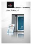
Optical Transmittance Analyzer
SL MA-110
0
1 2
3
4
5
6
7
8
9
Optical Transmittance Analyzer
SL MAMA-110
Supply: 12-24 VDC, 100 mA
Made in Germany
Laser Class 3A
User’s Manual
Sensor Line - Gesellschaft für
optoelektronische Sensoren mbH
Carl-Poellath-Str. 19
D-86259 Schrobenhausen
- Germany Tel.: +49 (0) 8252 / 8943-0
Fax.:+49 (0) 8252 / 8943-11
Email: [email protected]
www.sensorline.de
President/CEO:
Fred Motzko
Register Office:
Ingolstadt
HRB 101468
Address:
Sensor Line – Gesellschaft für
optoelektronische Sensoren mbH
Carl-Poellath-Str. 19
D-86529 Schrobenhausen/Germany
Tel.: +49-8252-8943-0
Fax: +49-8252-8943-11
eMail: [email protected]
Hp: www.sensorline.de
-1-
Bank Account:
Stadtsparkasse Schrobenhausen
IBAN:DE64 72151880 0000 221150
S.W.I.F.T.-BIC: BYLADEM1SSH
VAT: DE 181 207 708
SL MA 110 User's Manual
1. GENERAL ..........................................................................................3
2. CONNECTIONS ....................................................................................4
3. SIGNALS.............................................................................................4
3.1. The Analog Load Signal ..............................................................4
3.2. The Analog Monitor Signal ..........................................................5
3.3. The Digital Trigger Signal............................................................5
3.4. The Digital Error Signal ...............................................................6
4. FITTING AND STARTING ........................................................................7
5. SPECIFICATIONS..................................................................................7
President/CEO:
Fred Motzko
Register Office:
Ingolstadt
HRB 101468
Address:
Sensor Line – Gesellschaft für
optoelektronische Sensoren mbH
Carl-Poellath-Str. 19
D-86529 Schrobenhausen/Germany
Tel.: +49-8252-8943-0
Fax: +49-8252-8943-11
eMail: [email protected]
Hp: www.sensorline.de
-2-
Bank Account:
Stadtsparkasse Schrobenhausen
IBAN:DE64 72151880 0000 221150
S.W.I.F.T.-BIC: BYLADEM1SSH
VAT: DE 181 207 708
SL MA 110 User's Manual
1. General
The SL MA-110 Optical Transmittance Analyzer (OTA) is an electronic interface that supplies and
evaluates fiber optic load sensors. The SL MA-110 serves as the interface between the fiber optic
sensor and the processing unit. It should be installed indoors or inside a weatherproof road side
cabinet. A complete sensor system consists of the SL MA-110 interface with transmitter (LED) and
receiver (photodetector) connected by fiber optic feeder cable to the fiber optic load sensor.
Function:
The interface responds to the optical sensor signal in a dynamic (AC-coupled) manner, i.e. the
electrical signal caused when a load is applied to the sensor decreases to zero as the load remains
applied. At a threshold, a digital trigger signal is generated. This signal is automatically reset after a
certain time period. These characteristics allow the SL MA-110 interface to operate without the need
for adjustment.
If the interface detects an interruption in the light transmission path, it generates a digital error signal.
Both digital signals are transmitted via optocouplers which behave similar to relays, allowing the use of
a variety of output circuitry. The dynamic analogue load signal and the light power monitor signal also
have their own output clips.
Features:
•
•
•
•
•
•
•
•
•
•
•
Dynamic interface for detection of light power changes
Optocoupler digital outputs
Trigger output (optocoupler)
Error indication output
Analog output
Monitor output for normalizing the analog signal
Reverse power protection
Short circuit protection
Housing 67x58x25mm (2.6 x 2.3 x 1“)
IP 30 (NEMA 2) enclosure
10-pin screw clip
67mm (2.6in)
Screw Clip
60mm (2.36in)
Fitting Hole
0
1 2 3 4 5 6 7 8 9
SL MA-110
Supply: 12-24 VDC, 100 mA
45mm (1.77in)
Optical Transmittance Analyzer
Made in Germany
Laser Class 3A
SMA-Connectors
(905 Series)
20mm (0.8in)
Transmitter
LED LED
Sender
President/CEO:
Fred Motzko
Register Office:
Ingolstadt
HRB 101468
Address:
Sensor Line – Gesellschaft für
optoelektronische Sensoren mbH
Carl-Poellath-Str. 19
D-86529 Schrobenhausen/Germany
Tel.: +49-8252-8943-0
Fax: +49-8252-8943-11
eMail: [email protected]
Hp: www.sensorline.de
-3-
Photodetector
Bank Account:
Stadtsparkasse Schrobenhausen
IBAN:DE64 72151880 0000 221150
S.W.I.F.T.-BIC: BYLADEM1SSH
VAT: DE 181 207 708
SL MA 110 User's Manual
2. Connections
Electrical
Pin No
0
1
2
3
4
5
6
7
8
9
Signal
12 ... 24 VDC
GND
GND
Vref
Vmon
Vanalog
–ERROR
+ERROR
–TRIGGER
+TRIGGER
Description
Supply Voltage
Ground
Ground
Reference Voltage (about 5 V)
Analog Monitor Signal
Analog Load Signal
Negative Error Optocoupler Output
Positive Error Optocoupler Output
Negative Trigger Optocoupler Output
Positive Trigger Optocoupler Output
Optical
LED Transmitter, Photodetector
SMA-Connectors
(SMA series 905)
3. Signals
3.1. The Analog Load Signal
This signal shows the light changes which occur due to the load applied on the sensor in an
"AC-coupled“ manner.
To obtain the load signal connect Vanalog (pin 5) and Vref (pin 3) to a measuring device.
Either use Vref as reference voltage or measure both Vanalog and Vref with reference to
GND (Pin 2). In this case do the computation
Load Signal = Vanalog – Vref
President/CEO:
Fred Motzko
Register Office:
Ingolstadt
HRB 101468
Address:
Sensor Line – Gesellschaft für
optoelektronische Sensoren mbH
Carl-Poellath-Str. 19
D-86529 Schrobenhausen/Germany
Tel.: +49-8252-8943-0
Fax: +49-8252-8943-11
eMail: [email protected]
Hp: www.sensorline.de
-4-
Bank Account:
Stadtsparkasse Schrobenhausen
IBAN:DE64 72151880 0000 221150
S.W.I.F.T.-BIC: BYLADEM1SSH
VAT: DE 181 207 708
SL MA 110 User's Manual
3.2. The Analog Monitor Signal
In case the load signal is zero this signal shows the absolute light power transmitted by the
sensor. It is obtained as is the load signal but it is negative with reference to Vref.
Monitor Signal = – (Vmon – Vref)
As the light changes caused by the load are much smaller than the whole light power the
monitor voltage is amplified by a factor of 20 less than the load signal. In either case the
complete transmitted light power is proportional to the value
Monitor Signal – Load Signal / 20
To obtain a normalized load signal independent from the particular sensor's attenuation, do
the computation
3.3. The Digital Trigger Signal
As the trigger signal is transmitted via an optocoupler one of the following circuits is required
(Vsupply may be any external power supply).
The left circuit yields a positive trigger pulse, the circuit on the right side an inverted one.
The waveforms below show the signals caused by a vehicle crossing the sensor:
Upper graph: Vanalog (pin 5) related to Vref (pin 2)
President/CEO:
Fred Motzko
Register Office:
Ingolstadt
HRB 101468
Address:
Sensor Line – Gesellschaft für
optoelektronische Sensoren mbH
Carl-Poellath-Str. 19
D-86529 Schrobenhausen/Germany
Tel.: +49-8252-8943-0
Fax: +49-8252-8943-11
eMail: [email protected]
Hp: www.sensorline.de
-5-
Bank Account:
Stadtsparkasse Schrobenhausen
IBAN:DE64 72151880 0000 221150
S.W.I.F.T.-BIC: BYLADEM1SSH
VAT: DE 181 207 708
SL MA 110 User's Manual
Lower graph: Signal occurred at –TRIGGER (pin 8) with +TRIGGER (pin 9) connected to
+15V and a 10k pull down resistor from –TRIGGER to GND (pin 1, pin 2).
3.4. The Digital Error Signal
To obtain the Error Signal also one of the circuits on the previous page can be used.
If an Error signal occurs first check the monitor signal as described under 3.2. If this equals
to zero the transmission path is interrupted. In case it is below 250 mV the attenuation of the
transmission path exceeds the limit specified for proper operation of the triggering circuit.
This should not occur because the sensors are tested for attenuation. The interface may then
still work, but in certain cases the trigger signal may not be reset when the load is removed
from the sensor. Try cleaning the fiber connectors with a soft cloth. Be sure that neither the
sensors nor the feeders are bent over sharp edges. If this doesn’t help the sensor or the
feeders might be damaged and should be replaced.
President/CEO:
Fred Motzko
Register Office:
Ingolstadt
HRB 101468
Address:
Sensor Line – Gesellschaft für
optoelektronische Sensoren mbH
Carl-Poellath-Str. 19
D-86529 Schrobenhausen/Germany
Tel.: +49-8252-8943-0
Fax: +49-8252-8943-11
eMail: [email protected]
Hp: www.sensorline.de
-6-
Bank Account:
Stadtsparkasse Schrobenhausen
IBAN:DE64 72151880 0000 221150
S.W.I.F.T.-BIC: BYLADEM1SSH
VAT: DE 181 207 708
SL MA 110 User's Manual
4. Fitting and starting
1) Fit the interface with screws.
2) Remove the safety caps from LED transmitter and photodetector.
3) Connect the sensor SMA connectors with transmitter and photodetector.
When fastening the sensor SMA connectors with transmitter and photodetector a strong
torque must be applied in order to guarantee smallest attenuation, but do not use any
pliers. The connectors of transmitter and photodetector are allowed to be interchanged.
4) Connect the pins 0 (Supply Voltage) and 1 (Ground) to the power supply.
5) Connect the signal outputs (pin 2 to 9)
6) Turn on power supply
7) Test the installation by driving over the embedded sensor and monitor the Trigger signal
(pin 8 and 9) or Vanalog signal (pin 5). Test the sensor Error signal (pin 6 and 7) by
disconnecting one of the fiber connectors.
5. Specifications
Technical Data
Housing:
Size:
Protection Class:
Connection:
Optical Interface:
LED Type
LED Peak Output Wavelength
Relative Humidity:
Temperature Range:
Supply Current:
Supply Voltage:
Analog Output:
Optocoupler Output max.:
Velocity Range:
Feeder Length:
LED Risk Group:
Plastic
67 x 58 x 25 mm
IP 30
Screw clip, 10 pins
SMA 905
Red High Power LED / GaAlAs
660 nm, Visible / 850 nm IR
80% at 25°C
-40°C to 85°C (-40°F to 185°F)
< 100 mA
+12 to +24 VDC
0-10 V
60V/25mA
1 to 250 km/h
up to 250 meters
RG 0 (safe) *
* According to DIN EN 62471. Please note: In spite of the official classification
SENSOR LINE recommends to avoid staring into the transmitter for longer
periods, regardless whether light is visible or not.
President/CEO:
Fred Motzko
Register Office:
Ingolstadt
HRB 101468
Address:
Sensor Line – Gesellschaft für
optoelektronische Sensoren mbH
Carl-Poellath-Str. 19
D-86529 Schrobenhausen/Germany
Tel.: +49-8252-8943-0
Fax: +49-8252-8943-11
eMail: [email protected]
Hp: www.sensorline.de
-7-
Bank Account:
Stadtsparkasse Schrobenhausen
IBAN:DE64 72151880 0000 221150
S.W.I.F.T.-BIC: BYLADEM1SSH
VAT: DE 181 207 708
SL MA 110 User's Manual
Important notice
All the information contained herein is believed to be accurate and reliable. However, SENSOR LINE
assumes no responsibility for its use or for any infringements of patents or other rights of third parties
that may result from its use. No license is granted by implication or otherwise under any patent rights
of SENSOR LINE GmbH.
SENSOR LINE GMBH SHALL NOT BE LIABLE FOR ANY SPECIAL, INCIDENTAL, OR
CONSEQUENTIAL DAMAGES RELATED TO THE USE OF THIS PRODUCT.
All rights reserved. Reproduction or adaptation of any part of this documentation beyond without
permission of the Copyright owner is unlawful.
T.Faul 26.09.2013
© Copyright 2012 by:
President/CEO:
Fred Motzko
Register Office:
Ingolstadt
HRB 101468
Address:
Sensor Line – Gesellschaft für
optoelektronische Sensoren mbH
Carl-Poellath-Str. 19
D-86529 Schrobenhausen/Germany
Tel.: +49-8252-8943-0
Fax: +49-8252-8943-11
eMail: [email protected]
Hp: www.sensorline.de
-8-
Bank Account:
Stadtsparkasse Schrobenhausen
IBAN:DE64 72151880 0000 221150
S.W.I.F.T.-BIC: BYLADEM1SSH
VAT: DE 181 207 708