1
SINUS PENTA
INSTALLATION
INSTRUCTIONS
0
1
2
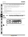
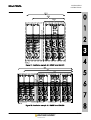
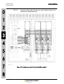
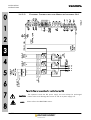
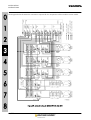
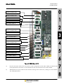
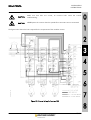
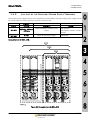
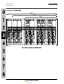
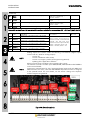
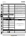
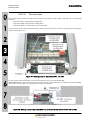
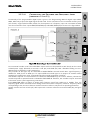
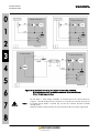
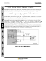
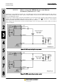
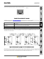
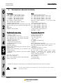
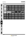
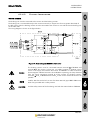
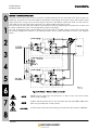
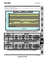
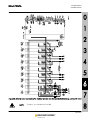
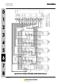
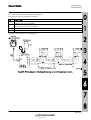
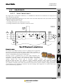
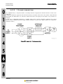
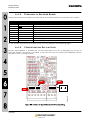
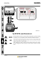
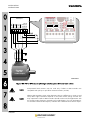
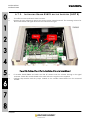
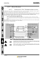
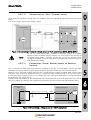
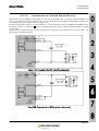
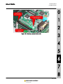
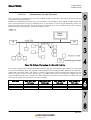
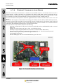
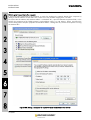
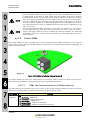
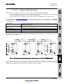
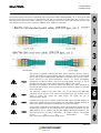
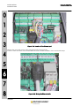
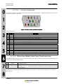
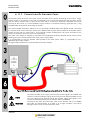
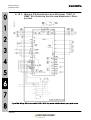
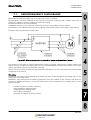
Figure 125: Example of a Profibus multidrop network; the correct setting of the line terminators is highlighted
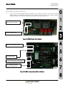
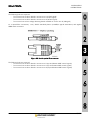
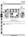
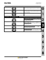
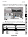
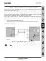
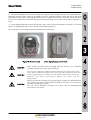
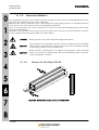
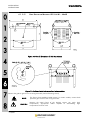
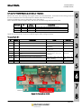
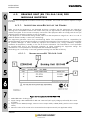
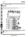
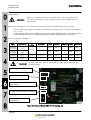
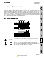
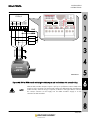
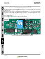
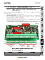
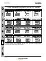
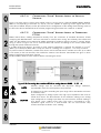
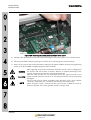
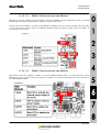
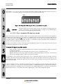
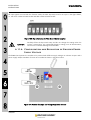
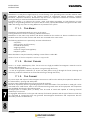
Each device in the network must have its own Profibus address. The addresses of the inverters of the Sinus
PENTA series are set through the rotary-switches installed in the interface board. Each rotary-switch is provided
with a pin that can be turned to position 0-9 using a small screwdriver.
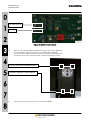
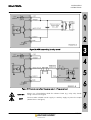
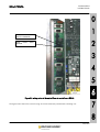
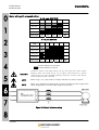
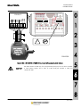
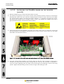
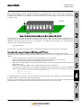
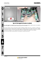
The left rotary-switch allows to set the tenths of the Profibus address, while the right rotary switch allows to set
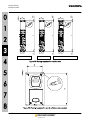
the units. Figure 126 shows an example of the correct position to set address “19”.
3
4
5
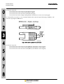
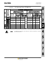
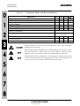
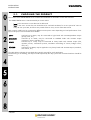
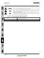
Figure 126: Example of the rotary-switch position to set Profibus address “19”
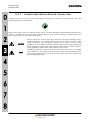
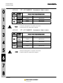
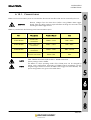
NOTE
The rotary-switches allow to set Profibus addresses ranging from 1 to 99.
Addresses exceeding 99 are not yet allowed.
6
7
8
261/321