1
User Guide for New functions SmartControl 1.4.doc
User Manual SmartControl 1.4
This document describes the Modifications and Functions which are newly introduced
in the Software SmartControl 1.4
Content:
1. Multi TCP/IP On- and Offline
2. Candisplay
3. Offline Alarm
4. Automatic Alarm Prints
5. MKT Stability Report
1. Multi TCP/IP On- and Offline
The existing functionality of the TCP/IP connection is extended in a way, that
configured IP addresses in the system table, could be used in the online as well
as in the offline mode. The communication layer was extended so that for each
system table, a communication component could be assigned, if configured for
this purpose. In case a system table has no configuration for the possible
connection, the chosen connection type under Set/Serial Interface will be used.
For the configuration of the connection type the respective functionality in the
SmartControl must be activated.
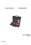
Fig 1: System table with configured TCP/IP-connection
A configured TCP/IP connection is used preferably. If the system table contains a
phone number (meaning, in the standard configuration Set/Serial Interface, a
modem connection was chosen) and a TCP-IP address, a connection for this
system table via TCP/IP will be established. In case a system table does not
contain a phone number for the modem connection and no IP address, a phone
number will be asked before connecting. Configured connection type here has to
be a modem.
01.03.2005
Page 1/11
User Guide for New functions SmartControl 1.4.doc
If the communication type under Set/Serial interface is set to modem and all
system tables are set to connect via TCP/IP, the modem connection will not open.
The communication will be established via TCP/IP.
- The following connection types are possible:
- 1*serial, several TCP/IP connections
- 1*Modem, several TCP/IP connections
- Several TCP/IP connections
- Several modem and TCP/IP connections (several modem connections offline
only)
- Several modem connections (offline only)
Unnecessary connections will not be opened by the software.
To activate the TCP/IP connection of the system table, you must enter in the field
host a valid object address. The entry contains IP address and port number of the
desired host and has the format XXX.XXX.XXX.XXX,YYYY, whereby XXX is the
IP address und YYYY is the port number of the host. Both parts of the address
are separated by a comma. If the port number is omitted, the port number 8000
will be used as standard.
A symbolic name could as well be used as alternative to the host address. This
should however be known by the system (a respective entry in the file
(%windir%)\System32\Drivers\Etc\hosts must exist).
To test the host connection, you may use the key beside the entry line.
All kinds of measuring data recording (online or offline) is based on system table.
If devices are available but not assigned to a system table, they will not be used in
the recording process. This makes it possible to take out devices temporarily from
the measuring process if necessary. The channels and the measuring data of
these devices still exist unless completely deleted. These excluded channels will
not be shown while selecting channels for display or for deleting memory. A hint
appears, if you close the measurement setup with deactivated devices.
01.03.2005
Page 2/11
User Guide for New functions SmartControl 1.4.doc
2. Candisplay
For the newly developed device Candisplay, the software is extended to
identifying, recording and writing of the E², and to manual and automatic
configuration. A Candisplay contains no measuring channel.
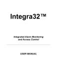
Fig 2: Configuration Candisplay
Configuration:
Next to the general parameter register is the register Candisplay Configuration,
where specific parameters of the Candisplay may be set.
Active Display Channel:
The Candisplay can display between 0 to 4 measuring values.
Here, you may chose the number of measuring values to be displayed.
The number of measuring values set to be displayed corresponds to the number
of displays activated e.g. "Display 1" until "Display 4".
Display Brightness:
You may set here the display brightness ranging from level 1 (dark) to level 4
(bright).
Alarm Signal:
Candisplay alarms in 5 different alarm frequencies (1-5). You may chose here
which alarm frequency is to be used.
01.03.2005
Page 3/11
User Guide for New functions SmartControl 1.4.doc
Alarm frequency:
You may set the alarm frequency between 500 and 3000 Hertz. This choosen
frequency will be shown in the field alarm signal.
Alarm pause:
After acknowledging the alarm you may set here the alarm pause using the key of
the candisplay. You may set values minutewise between 1 min and 20 minutes.
Measuring value gap until line:
Upon finishing your online measurement, you may now configure at which time
your measuring values will be indicated as a line (based on the memory rate of
the channels to be displayed). The values to be set may range between 0 and
255 saving rate. For example: If the memory rate of a channel to be displayed is 1
min. and the measuring process was stopped, the last measured value will be
indicated for 255 minutes.
Audible Alarm:
Via check box " Audible Alarm", you may switch the audible alarm of the
candisplay ON or OFF. If the audible alarm was switched OFF and an alarm exist,
the deactivated audible alarm will not send a signal. However, other alarm
possibilities of the candisplay remain active (blinking) and will signal alarm.
Display 1 until Display 4
In the "Channels to be displayed", all active channels of a system table are listed.
If you chose a channel, the parameters of the display with the corrresponding
parameters of the channel will be configured. In the "Label", you may enter and
edit the first 16 characters of your channel description . In "Display by", you may
configure which value (Mean, Min, Max or Sum) of the channels should be
displayed. The selection is however limited depending on the channel
configuration. If the choosen channel measured only the mean value, this
selection will be the only one active.
Automatic Configuration:
If changes in the configuration of Opus devices result in changes of candisplay
configuration, these modifications will be automatically be set and programmed in
the candisplay.
The candisplay will likewise be reconfigured if the channels to be displayed are
inactivated or if Opus is taken out of the respective system table.
During joining of files the candisplay configuration will be scanned of necessary
changes. The programming of candisplay could as well be left undone if the user
desires it so.
01.03.2005
Page 4/11
User Guide for New functions SmartControl 1.4.doc
3. Offline Alarm
In the Version 1.4, the SmartControl is extended so that alarms could be tracked
down by reading memory and that alarms could be listed down and displayed.
Alarm settings of the channels (alarm suppression etc.) will be taken into
consideration during tracking down of alarms.
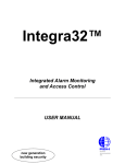
Fig. 3: List of alarms from memory reading
The shown list in Fig. 3 contains alarms which are determined by memory
reading. Other "unacknowledge alarms" will not be shown in this list.
Hint: If you read the memory of the same period several times, the determined
alarms will be listed down several times as well. Please remember this when
reading memory. Should data reading be done several times, it is suggested to
switch OFF alarm determination.
Fig. 4: Dialog time entries by maual memory reading
In reading memory manually, you may switch ON or OFF the function,
determination of events by using the check box "determine event by reading
memory".
You may likewise tick the check box ON or OFF in the dialog Options/System
Settings in the menu "Events".
01.03.2005
Page 5/11
User Guide for New functions SmartControl 1.4.doc
4. Automatic Alarm Printout
The automatic alarm printout will be done on reaching default (user defined)
values and includes a Single Channel Y/t Diagram and the corresponding Single
Event Printout of that event.
The processing of the printouts is independent of the alerting on the screen and
on the central actor as well as the acknowledgments of the alarms.
If an automatic processing should be done can be switched on and off with the
checkbox "Automatic alarm print-out" in the dialog Options/Systemsettings.
If the whole eventprocessing is deactivated, then no alarm print-outs will be
generated.
The rules for the processing are defined as:
The automatic alar Printout should be done, if a limiting value violation has
occured and the measuring value is again within the limits
and
the duration of the violation was longer than "Alarm Period" (4h)
or
the temperatur deviation was larger than "Delta-T" (5 °C) (since start of the
violation)
or
the humidity deviation was larger than "Delta-H" (10 % rel.) (since start of the
violation)
Configuration
Under Options/Systemsettings... the parameters for the processing could be
changed as follows:
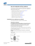
Fig 5: Configuration of the automatic alarm print-out.
Alarm Period:
You may enter here the minimum alarm period desired before the automatic
printing process starts. The alarm period could be set secondwise and could be
between 00 hours, 00 minutes, 00 seconds and 23 hours, 59 minutes 59
seconds. The pre-set values are 4 hours, 0 minutes and 0 second.
01.03.2005
Page 6/11
User Guide for New functions SmartControl 1.4.doc
Delta-T:
A Delta-T may be pre-set for temperature channels. If the value is exceeded an
alarm signal will be sent even if the alarm period is not exceeded. The pre-set
value is 5.0 °C.
Delta-H:
A Delta-H may be pre-set for temperature channels. If the value is exceeded an
alarm signal will be sent even if the alarm period is not exceeded. The pre-set
value is 20.0 %rH.
Pre-scaling:
If an automatic alarm print-out is set, a diagram with the graph of the
corresponding channel will be printed out. You may configure in this field at what
time before the first alarm occurs should the diagram be scaled.
01.03.2005
Page 7/11
User Guide for New functions SmartControl 1.4.doc
5. MKT Stability Report
The SmartControl is extended to calculating, indicating and printing-out the Mean
Kinetic Temperature. The purpose of the MKT (Mean Kinetic Temperature)
calculation is to assess the relevance of a short time temperature deviation for the
product quality throughout the storage period.
To generate the MKT stability report, activate under Evaluation the menu item
"MKT Stability Report".
The following dialog will guide you through report configuration:
Fig. 6: Information und start MKT Stability Report configuration
Hint: To activate this dialog a file must be loaded. You may as well activate the
dialog during online measurement. You may exit the configuration of the MKT
stability report anytime using the "Cancel" key.
Aside from general information about MKT report, you have the possibility to load
a saved report definition or generate a new definition. Select the key
"Configuration" to start.
01.03.2005
Page 8/11
User Guide for New functions SmartControl 1.4.doc
Fig. 7: Channel selection for the MKT Stability Report
The list shown contains all available temperature channels of the loaded file.
Check-mark the channels which should be considered in the MKT report and then
click the key, "Continue."
By clicking the column title ("Channel", "Sensor" etc.), you may change the sorting
of the list.
Fig. 8: Define Report Period for the MKT Stability Report
You may define here the report period of your MKT report. The list on the right
side contains the defined period. To define a report period enter it on the left side
then use the key "Insert >>" to put it in the list. You may enter as many period as
you wish (also non-continuous).
Using the key "Delete Line", the marked line on the list will be deleted. Using the
01.03.2005
Page 9/11
User Guide for New functions SmartControl 1.4.doc
key "Empty Table", the entire list will be deleted. Using the key "Change",the
selected entry on the list will be overwritten with the actual data from the entry
field.
Fig. 9: Additional Report Parameter
In this dialog, you may chose which MKT calculation is prefered and which report
structure is desired.
Constant Delta-H:
Constant Delta-H is the activating energy in kJ/mole. The value is 83.144 kJ/mole.
Constant R:
R is the universal gas constant in kJ/mole * K and has the value 0.0083144.
Method of Mean Calculation:
The method of mean calculation shows ways of computing the necessary mean
temperature value. You may chose between daily- or weekly mean value. Daily-or
weekly mean values however are calculated from: all measuring values of an
intervall (Daily- or Weekly intervall: mean value of all measuring values) or from:
the lowest and the highest measuring values of an intervall (Daily-or Weekly
intervall: mean value from the lowest and the highest measuring values).
You may likewise chose here, if the MKT should be calculated using the channel
unit or the unit Kelvin.
01.03.2005
Page 10/11
User Guide for New functions SmartControl 1.4.doc
Fig. 9: Summary and Processing of Reports
In this dialog, the configured report parameters of the MKT are summarized.
You may save here your report with its configured parameters under a definite
name. This enables you to load the saved report parameters for other reports.
The key "Execute" is not active if all necessary parameters are incomplete. If the
key is active you may start the processing of your report. For the calculation and
display of the MKT report, the software starts a second window and transfers the
configuration. This allows you to process your MKT report and to run your online
measurement simultaneously.
01.03.2005
Page 11/11