1
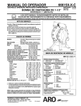
48619852
Edition 1
July 2012
QX Series Display
User Manual
Save These Instructions
Table of Contents
Purpose of the document:
-
1
1.
Overview of different Menu screens ......................................................................................................................................2
2.
Description of the Display screen in detail...........................................................................................................................4
2.1.
2.2.
2.3.
Run Screen .............................................................................................................................................................................................4
Configuration ........................................................................................................................................................................................5
Password .................................................................................................................................................................................................6
2.3.1.
2.3.2.
2.3.3.
2.3.4.
2.3.5.
2.3.6.
2.3.7.
2.3.8.
2.3.9.
2.3.10.
2.3.11.
2.3.12.
2.3.13.
2.4.
2.5.
2.6.
2.7.
2.8.
Updating parameters of the QX Series tool .................................................................................................................................... 9
Radio Enable/Disable .............................................................................................................................................................................. 9
Gang count ...............................................................................................................................................................................................10
Shiftdown Speed ....................................................................................................................................................................................10
Shiftdown Point Config ........................................................................................................................................................................11
Free Speed.................................................................................................................................................................................................11
Torque Threshold ....................................................................................................................................................................................12
Angle ...........................................................................................................................................................................................................12
Torque .........................................................................................................................................................................................................13
Unit of the Torque...................................................................................................................................................................................14
Direction of Rotation .............................................................................................................................................................................14
Strategy ......................................................................................................................................................................................................15
Save / Ignore Settings ...........................................................................................................................................................................15
Warning Screen ................................................................................................................................................................................. 16
Shunt Calibration, RF Signal Strength and Battery level .................................................................................................... 16
Cycle count.......................................................................................................................................................................................... 17
Angle ..................................................................................................................................................................................................... 17
Torque ................................................................................................................................................................................................... 18
Appendix 1 : Status LED Definitions ............................................................................................................................................ 19
Appendix 2 : Tool Fault codes ........................................................................................................................................................ 19
Parts and Maintenance...................................................................................................................................................................... 20
i
48619852_ed1
Purpose of the document:
This document provides details about different menu screens, their description and how to edit those screens in display
module, required for the operation of QX Series Hand Tool.
The image Below shows the display of QX Series display module with descriptions of the programming keys.
UP
ESCAPE
ENTER
LEFT
RIGHT
DOWN
Symbol
Function
Escape / Exit
Enter / Edit
UP
DOWN
RIGHT
LEFT
48619852_ed1
1
1.
Overview of different Menu screens
Power up QX Series tool
RUN SCREEN
Press “UP” key
Displays Configuration
Number being used
Always Press “UP” key to
go to next screen
Press “ENTER” to enter “EDIT” mode
Password screen
Current fault
Status screen with shunt cal,
wireless strength and
battery level.
Cycle count
Target Angle, Low
and High screen
Target Torque Low
and High screen
RUN SCREEN
2
Press “UP” key to
increment the value
Press “DOWN” key to
decrement the value
Press “ESC” to undo
and keep the old values.
Press “ENTER” to select
the changed values.
After display is unlocked
Press “RIGHT” Key
Press “UP” key to go to
next screen
Save or Ignore changes.
If not on Save screen, use the up or down key
to scroll to the Save screen.
Press “UP” key to scroll
on one by one to get
below editable screens
in series
48619852_ed1
Strategy – Angle or Torque
Direction – Clock wise or anti clockwise
Unit of Torque
Target Angle (Angle strategy) OR
Target torque (Torque strategy)
Torque High
Torque Low
Angle High
Angle Low
Torque threshold
Free Speed
Shift down torque
Shiftdown Speed
Gang count
Enable / disable RF module
Save / ignore the changes settings
48619852_ed1
3
2.
Description of the Display screen in detail
There are three sections in the QX Series display screen, one “PRIMARY” on the top and two “SECONDARY” which are on
left and right bottom of the display.
2.1.
Run Screen
Pressing “ENTER” key after switching on the display will show this image.
PRIMARY Section - shows latest peak torque (for a torque strategy) or the latest peak angle (for an angle strategy), with
units.
The SECONDARY LEFT - shows the cycle count or gang count, if gang count is programmed.
The SECONDARY RIGHT - shows the active configuration number.
4
48619852_ed1
2.2.
Configuration
Pressing “UP” will advance to next screen.
Screen shows CONFIGURATION setting used in the tool.
NOTE: Only Configuration 1 can be programmed through the display module.
Pressing “ENTER” will enable the “EDIT MODE” (This procedure to enter “EDIT MODE” is same for all settings update)
48619852_ed1
5
“UP” or “DOWN” key can be used to update the configuration. Pressing “ENTER” again will select the modified
configuration.
2.3.
Password
The password screen shows whether the display is locked or unlocked. If the display is locked the parameters of the QX
Series Hand tool cannot be edited.
6
48619852_ed1
Password can be changed by entering into “EDIT MODE” and using “UP” or “DOWN” key.
If “1234” is entered on the Password screen, the user may use the left arrow to go to the Tool ID and software version
page
The Primary Display is the “Tool Location ID”.
Lower Secondary Right is the “Display Firmware” Version.
Lower Secondary Left is the “Motor Controller Firmware” Version.
48619852_ed1
7
Displays Tool time in HH:MM:SS format. Press the Down key to display the tool time in HH:MM:SS format.
Remaining screens are for internal use only to view log location. Press the Down key to display a screen for internal use
only to view log location. Press the Down key again to display a second log screen.
Press the Down key again to return to the Tool ID page. Pressing the right arrow from this page exits back to the
password display.
8
48619852_ed1
Press ‘ENTER’ to enter the ‘EDIT’ mode. Enter the appropriate password to unlock the tool. Press ‘ENTER’ to exit the ‘EDIT’
mode.
2.3.1.
Updating parameters of the QX Series tool
After display is unlocked with a valid password, Pressing “RIGHT” key will advance to following settings that can be
modified as required.
The settings can be modified by entering “EDIT MODE” and using “UP” or “DOWN” key or “RIGHT” or “LEFT” key as
required.
2.3.2.
Radio Enable/Disable
This screen allows the user to enable or disable the radio module. The selection on the left disables the radio module
and the selection on the right enables the radio module.
RADIO DISABLED
]
48619852_ed1
RADIO ENABLED
9
2.3.3.
Gang count
The below screen shows the gang count number of bolts to be fastened per Group, Gang, or Set for Configuration 1.
This can be modified by entering “EDIT MODE”.
2.3.4.
Shiftdown Speed
This screen indicates shiftdown speed of the QX Series tool. Shiftdown speed can be edited by entering “EDIT MODE”
and updating using UP and DOWN arrow. Programmed speed is a percentage of tool maximum speed.
10
48619852_ed1
2.3.5.
Shiftdown Point Config
This screen indicates “Torque Threshold for shiftdown point”. This can be changed by entering “EDIT MODE” and
updating using “UP” or “DOWN” key.
2.3.6.
Free Speed
The below screen indicates free speed of the QX Series tool. The value can be edited by entering “EDIT” mode and using
“UP” and “DOWN” arrow. Programmed speed is a percentage of tool maximum speed.
48619852_ed1
11
2.3.7.
Torque Threshold
The Torque at which reading of the angle will be started. The value can be edited by entering “EDIT” mode and using
“UP” and “DOWN” arrow.
2.3.8.
Angle
Angle “LOW” Display
Angle “HIGH” Display
Angle “LOW” can be modified in this mode by
entering “EDIT” mode and using “UP or “DOWN” key.
Angle “HIGH” can be modified in this mode by
entering “EDIT” mode and using “UP or “DOWN” key.
12
48619852_ed1
2.3.9.
Torque
Torque “LOW” Display
Torque “HIGH” Display
Torque “LOW” can be modified in this mode by
entering “EDIT” mode and using “UP or “DOWN” key.
Torque “HIGH” can be modified in this mode by
entering “EDIT” mode and using “UP or “DOWN” key.
Torque “TARGET” Display
Torque “TARGET” can be modified in this mode by entering “EDIT” mode and using “UP or “DOWN” key.
48619852_ed1
13
2.3.10. Unit of the Torque
Indicates unit of the Torque displayed in Configuration 1.
This can be changed by entering “EDIT MODE” and updating using “UP” or “DOWN” key.
2.3.11. Direction of Rotation
Image shows direction of rotation in which the QX Series hand tool rotates.
Indicates counter clock wise rotation
Indicates clock wise rotation
This can be changed by entering “EDIT MODE” Key and updating using “RIGHT” or “LEFT” key
14
48619852_ed1
2.3.12. Strategy
This screen indicates configuration strategy being used.
Left – Angle, Right – Torque
The pointing arrow indicates the present configuration being used.
This can be changed by entering “EDIT MODE” and using “RIGHT” or “LEFT” key
2.3.13. Save / Ignore Settings
After all the required changes are completed, Press enter to highlight the save settings box on the left. Press the right or
left arrow key to select cancel on the right. Pressing enter a second time causes the tool to leave edit mode.
SAVE SETTINGS
CANCELSETTINGS
48619852_ed1
15
2.4.
Warning Screen
This is the next screen obtained after pressing “UP” key when QX Series displays the Password screen.
2.5.
Shunt Calibration, RF Signal Strength and Battery level
This is the next screen obtained after pressing “UP” key when QX Series displays password screen.
Primary display indicates Shunt Calibration Value.
Secondary display on left indicates RF signal strength and the one on the right indicates Battery Level.
16
48619852_ed1
2.6.
Cycle count
This value shows number of cycles run by the QX Series tool, Since the last time it was changed.
With the tool unlocked, press ‘ENTER” key to edit this screen. Press either the ‘UP’ or ‘DOWN’ key to clear the cycle count.
For this change to be retained a cycle must be run before removing power to the tool. Otherwise, the old cycle count is
restored.
2.7.
Angle
Primary display – Target Angle
Secondary Display on left - Angle low
Secondary Display on right - Angle High
48619852_ed1
17
2.8.
Torque
Primary Display -Target Torque
Secondary display on left - Torque low
Secondary display on Right - Torque high
Pressing “UP” advances back to “RUN SCREEN”, the first display screen.
18
48619852_ed1
Appendix 1 : Status LED Definitions
There are four LEDs on the display module. 3 on the top and 1 below the display screen.
The Status LEDs shall be used as follows:
Red
--
The last tightening cycle exceeded its high limit
Yellow --
The last tightening cycle ended below its low limit
Green
--
The last tightening cycle ended between its high and low limits
Blue
--
The tool has an active fault condition.
Appendix 2 : Tool Fault codes
The tool shall report the following fault codes for the listed conditions:
F-01
Tool Disabled (by external control)
F-02
Rapid Trigger pull – trigger was pulled before configuration delay was complete
1-FF
USB enumeration fault
A-10
Motor controller communication timeout
A-55
A display software version update was detected
B-01
Failure to update Motor Controller Software
B-85
RF ACK Timeout (we did not get a serial ACK messages from the transceiver)
B-E1
RF Transmit NAK–“Channel Access Failure”
B-E5
RF Transmit NAK–“Frame Too Long”
B-E9
RF Transmit NAK–“No ACK Received”
C-01
Configuration ID value is 0 or greater than 8
C-02
Number of configuration steps is greater than 8
C-03
Current Step ID is greater than the current number of steps
C-04
Total Gang is greater than 8
C-05
Current Gang count is greater than Total Gang
C-06
Current Torque High Limit is greater than the Tool’s maximum Torque value (Tool’s max torque value
is configured in the Factory Set Points) OR Current Torque High Limit is less than 0
C-07
Current Torque Low Limit is greater than the Tool’s maximum Torque value OR Current Torque Low
Limit is less than
C-08
Current Torque High Limit is less than Current Torque Low Limit
C-09
Current Torque Low Limit is greater than Current Torque High Limit (Fault code to be removed)
C-0A
Current Angle High Limit is greater than the Tool’s maximum Angle value (to be set to 9999)
C-0B
Current Angle Low Limit is greater than the Tool’s maximum Angle value (to be set to 9999)
C-0C
Current Angle High Limit is less than Current Angle Low Limit
C-0D
Current Angle Low Limit is greater than Current Angle High Limit (Fault code to be removed)
C-0E
Tool configuration step is a Target torque and the target value is outside the torque high and low limits
C-0F
Tool configuration step is an Target Angle and the target value is outside the angle high and low limits
C-10
Tool configuration step is not set for either Angle or Torque
C-11
Current Threshold value is greater than the maximum tool torque OR Current Threshold value is less than 0
C-12
Current Free Speed is greater than maximum motor speed
C-13
Current Shiftdown Speed is greater than maximum motor speed
C-14
Current display unit value is unsupported
C-15
Torque Threshold exceeds target (with torque target) or max torque (with Target Angle)
C-55
Invalid Configuration selection
E-00
Battery Fault
E-01
Invalid Hall State
48619852_ed1
19
E-02
I2T Fault
E-03
Motor Stall
E-04
Over Current
E-05
Over Temperature
E-06
Current Off set Fault
E-07
Shunt Calibration Fault
E-08
Torque Offset Fault
E-09
Transducer Fault
E-0A
Step Execution Timeout
E-0B
Configuration Execution Timeout
E-0C
Over Torque Limit
E-0D
Over Angle Limit
E-0E
Current Plausibility High
E-0F
Under Torque
E-10
Under Angle
E-11
Current Plausibility Low
E-12
Early trigger Release
E-13
Motor Controller Watch dog Reset
E-14
Brake Timeout
E-18
Missed Run Steps (Prevailing Torque configuration did not complete)
E-1B
Battery Cell Fault (detected by Motor Controller)
E-1C
Low Battery Fault (detected by Motor Controller)
E-1D
Critical Battery Fault (detected by Motor Controller)
E-1E
Motor Controller is shutting down
E-1F
Wakeup Code received (but not expected)
E-81
The configuration ID in the Motor controller’s EOR did not match the currently selected configuration
2-<Alarm ID> PM Alarm Time Fault for corresponding Alarm ID normally configured by the user
3-<Alarm ID> PM Alarm Cycle Fault for corresponding Alarm ID normally configured by the user
C-16
Number of configuration steps is set to 0
Parts and Maintenance
Original instructions are in English. Other languages are a translation of the original instructions.
Tool repair and maintenance should only be carried out by an authorized Service Center.
Refer all communications to the nearest Ingersoll Rand Office or Distributor.
20
48619852_ed1
Notes:
48619852_ed1
21
www.ingersollrandproducts.com
© 2012 Ingersoll-Rand, plc