1
Wolfgang Schreiner Dipl.Ing.(FH)
Rüttlenäckerstr.6
88094 Oberteuringen
Hard- & Software Entwicklung
email: info#wstech.de # durch @ ersetzen
homepage: www.wstech.de
9/2006
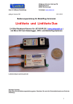
User Manual for Variometer Classic Sound Voice
Those unfamiliar with the electric variometer may be inclined to view it with some suspicion: they may
feel it destroys the peace of soaring flight, and merely adds to the mental confusion. But after a few
flights one comes to regard it as an essential aid to soaring.
Welch & Irving “New Soaring Pilot”1955
Technical Data & Specifications
Dimensions
Weight
Sensitivity
Altitude
R/C Voltage
Voltage
Current
Range
Transmit power
Frequency
Bandwidth
Antenna
67x27x15 mm (2.6x1.1x0.6 in)
29 g (1.0 oz)
5 cm/s (10 ft per minute)
Height announcements between -1,000 ft or 300m and +
10,000 ft or 3000m
with a resolution of 10 ft or 3m
R/C voltage resolution 0.01V
4.8V to 8.5V (4 or 5 cell NiMh or 2S LiPo receiver battery)
65 mA at 5V
2 km (1.2 miles)
10 mW
433.0625 to 434.7875 MHz in 12.5 kHz steps. See appendix 1
+/-2.5 kHz
17 cm (7 in) flexible wire
Advantages of a Variometer
The variometer, commonly shortened to vario, helps the pilot to find thermals and to make best use of them. The
vario is most useful at height or when the model is overhead, because here it is particularly difficult to see if the
plane is in lift. wstech variometers have proved to be reliable and helpful aids to soaring flight for their many
users world-wide. With a climb indicator, the art of thermal soaring takes on a completely new charm, the joy of
keeping your model in the air for longer is unmistakable
Additionally the wstech Classic Sound Voice variometer has some very useful new features to improve safety and
enjoyment:
•
Battery voltage announcements.
•
Altitude announcements.
•
Loss of R/C signal announcements.
•
Minimum voltage and maximum altitude recording.
1
For full size gliders the vario is considered an indispensable instrument, and its use is taught from the first lesson.
After flying with a vario in a model glider you will appreciate the benefits are just as strong when flying from the
ground using R/C. However it does take a little patience to learn how to fit and use a vario, so please read these
instructions with care.
Functional Overview
The Classic Sound Voice variometer provides acoustic output only (no PC data logging functions) making it small
and comparatively inexpensive. It is designed to be used in small flying models and to provide rate of climb,
altitude, and voltage announcements. It has been engineered to deliver simplicity. No personal computer or other
processing device is required for its configuration or use.
A very useful facility of the variometer is that it can be sent commands via the R/C, allowing the user to choose
different operating modes. However if there are no free channels the variometer will operate in Altimeter Mode
with automatic climb, altitude, failsafe, and voltage announcements.
Technical Characteristic & Features
Vario Tonal Output
The WSTech vario’
s analogue circuitry has been designed to indicate lift or sink with a maximum of sensitivity and
accuracy. At the heart of the vario is a very sensitive temperature compensated pressure sensor. This converts
vertical movements of the model into a variable audio tone which is transmitted to the receiver. Height changes as
small as 5 cm/s (2“per second, or 10 ft per minute) will be indicated immediately by a change in tone. Sinking
produces a continuous tone which becomes deeper with increasing sink rate. Climbing gives a pulsed rising
sound. The pulse frequency rises as the rate of climb increases, so for increasing rates of climb the vario output
will sound like: duut, duut, dut, dut, dit, dit, etc.
Voice Output
The acoustic voice output of the vario is used to announce the model’
s altitude and R/C receiver battery voltage.
If connected to a receiver output it also provides failsafe announcements. In some variometer modes the change
in altitude is spoken. Additionally the maximum height and minimum voltage are stored during the flight and are
spoken when the variometer is next switched on.
Technical Info
The audio signal is transmitted to the pilot on the ISM 433Mhz band by a fully legal telemetry transmitter. The
crystal controlled transmitter conforms to all UK and EU regulations including BAPT 222 ZV 125 / I-ETS 300 220u
and ETS RES 0908. No telecommunications license is required by the user. The vario is fitted with an 8 pin DIP
switch to allow the exact transmitted frequency to be selectable within the legal range. Any one of 69 channels
can be used, allowing many modellers to be flying with variometers simultaneously without them interfering with
each other.
Because the variometer function of this product uses analogue circuitry it is particularly sensitive to small changes
in rate of climb or sink, which would be lost in the analogue to digital conversion process in a digital device.
Normally analogue circuits are sensitive to unwanted external inputs, especially RF radiation. However by
designing the circuit board layout optimally and screening the sensitive components the vario is totally unaffected
by high frequency radiation, whether it comes from the vario’
s telemetry transmitter, or the modeller’
s R/C
transmitter.
Ground station
To hear the audio tone the R/C pilot needs a suitable radio receiver to pick up the variometer’
s 433 MHz signal.
We supply and recommend LPD (Low Power Device) handheld radios (sometimes called walkie talkies) designed
for the ISM (Industrial, Scientific, and Medical) radio band. These radios can pick up all 69 channels and include
belt mounts and headphone outputs, so the pilot can privately listen to the tone without any encumbrances.
Please see http://en.wikipedia.org/wiki/Low-power_communication_device for more info about the band.
Handheld radio scanners or 70 cm amateur radio receivers can also be used with the vario. However do not use
PMR (Personal Mobile Radio) devices for the 448 MHz band.
Installation Directions
To gain full use of the vario functionality the device should be plugged into a spare receiver output, preferably
controlled by a 3 position switch (or alternatively a slider) on the transmitter. Should no free plug be available, a
dual aileron servo extension lead (or Y-lead) can be used to connect the vario, however operation of the control
function (ideally tow hook release) will of course also change the vario mode. If no spare R/C channel can be
used the vario can also be powered by an external 4.8V - 8.5V battery. However in this case the vario will only
operate in Altimeter Mode.
In fuselages that don’
t use carbon fibre the antenna can be fastened to the body wall. The antenna should be as
straight as possible. When mounting the antenna ensure it is not parallel to other cables or metal parts, as this
decreases the aerial’
s effectiveness and thus the range. (Incidentally this is also true for the R/C receiver’
s aerial.)
Finally, the vario’
s antenna should not be parallel to the R/C receiver aerial.
2
In fuselages that contain carbon fibre (even if only for local reinforcement) the antenna should be led out of the
fuse immediately, and either supported to make a whip aerial, or allowed to hang free in the air stream.
Variometer Modes
If the variometer is connected to a receiver output the vario can be commanded to operate in one of four modes.
These modes can be selected by a three position switch programmed to output a servo position of -100% travel,
centred, and +70% travel. (Hyperflight note: in our testing +100% worked OK too.) If a three position switch isn’
t
available a slider can also be used.
Note the above travel percentages are for all standard 1ms to 2ms pulse duration radios including, Graupner, JR,
and Futaba. For Multiplex transmitters operating in their native mode the percentages are -100%, -20%, and
+50% respectively.
Whenever a new mode is selected the variometer responds by beeping an acknowledgement signal. This is very
useful when programming the transmitter to ensure the variometer is correctly interpreting the signal. In flight it is
useful as a quick confirmation of the mode selected.
Mode
Tx
Slider
Position
Acknowledgement
Announcement function
Vario
tones
Integral
Mode
Altimeter
Mode
Low
-100%
Middle
0%
beep
Yes
Quiet
Mode
High
+70%
beep,
beep,
beep
Climb
Rate
Mode
High,
beep,
then low beeeep
+70%
then
-100%
Change of altitude every 20
seconds.
Altitude announcements
every 200 ft (100 ft in later
version) or after 60
seconds.
When activated altitude and
voltage is announced. No
further announcements are
made apart from voltage
changes.
Initially change of altitude
every 10 seconds. Then
automatically changes to
20 second intervals (ie
Integral Mode).
Integral Mode
beep
beep,
beep
-100%
Yes
Remark
Announces
altitude when
activated from
Integral Mode.
No
Yes
Only changes
to the 20s
interval after a
30ft height
gain.
Low
The Integral variometer Mode is ideal for thermal hunting. In this mode in addition to the standard variometer tone
(which gives near instant indication of lift or sink) the variometer also announces the change in altitude over the
last 20 seconds.
Feet version:
For example an announcement of “minus 40”means the model has lost 40ft on the last 20 seconds, equivalent to
a sink rate of 120 feet per minute. An announcement of “plus 25”indicated the model is in lift and is rising at a
rate of 75 feet per minute. The announcement of the unit of feet was left to keep the message short.
Meter version:
For example an announcement of “minus 18”means the model has lost 18m on the last 20 seconds, equivalent to
a sink rate of 0,9m/s. An announcement of “plus 12”indicated the model is in lift and is rising at a rate of 0,6m/s .
The announcement of the unit of meters was left to keep the message short.
This function is very helpful for centring in thermals, and for evaluating how bad areas of sink are. Another use is
for checking the sink rate at different elevator trims and at different flap positions - a little patience and calm
weather is required!
Since one gets to know the sink rate of the model with this function quickly, one can quickly recognize downdraft
areas and their severity. The regular 20 second time reference avoids the need for mental arithmetic and makes
the integral variometer mode one of the most popular. The 20 second interval gives a good trade-off between
variometer tone information and verbal announcements.
Manufacturer’
s Note: In our opinion this mode would be better called Differential Mode as the height difference is announced.
However the name Integral Mode is an industry standard for full size and model varios.
Altimeter Mode
beep, beep
0%
Middle
In Altimeter Mode the vario announces the model’
s height every time it crosses a 100ft or 50m altitude step, in
relation to the start altitude. The start altitude is calibrated automatically to zero feet when switching on. The
altitude must change by at least 30 ft or 20m for the previous altitude to be re-announced.
3
Also the altitude will be announced after 60 seconds if there hasn’
t been a height-change caused announcement.
Quiet Mode
beep, beep, beep
+70%
High
On switching to Quiet Mode the variometer announces once the current altitude and the receiver voltage. Both the
variometer tone and the height announcement cease after that. However the voltage is continued to be monitored
and any change of voltage is immediately announced.
Climb Rate Mode beep, beeeep
+70% then -100%
This is essentially the same as the Integral Mode but with the time interval reduced to 10 seconds. It is especially
useful for electric glider pilots for measuring the climb rate under power.
Once activated the time interval automatically changes to 20 seconds (Integral Mode) once the model ceases
climbing. A height gain of at least 30 feet or 10 meters is required for this automatic mode change.
To select this mode first select Quiet Mode and then directly switch to Integral Mode.
All Modes - Voltage Announcements & Failsafe
The current receiver/variometer voltage is announced after start-up. An automatic voltage announcement is also
transmitted whenever the voltage falls by 0.1V for one second below the previous low. If the voltage falls as low
as 4.6V the vario transmits a 3 seconds continual warning tone (djui djui djui)
If the receiver can be setup for failsafe operation the vario will announce a loss of transmitter signal by voicing
“Failsafe”. For this to work the receiver channel that the vario is connected to has to be programmed to go to at
least +140% travel on loss of transmitter signal.
Adjusting the Climb Threshold
Important: The vario has been correctly adjusted for a zero sink (0 fpm) climbing threshold before
delivery. We recommend users do not change this setting. Please alter factory settings only if you’re fully
familiar with the variometer.
The climb threshold can be adjusted using the multi turn potentiometer. This is useful for tuning the response of
the vario to the model and your style of flying.
A one turn anticlockwise change corresponds to 0.5m/s (100ft per min) of climb. One turn in the clockwise
direction represents a threshold of 0.5m/s of sink.
1.
Place the model on the table or on the ground and power-up the vario (using the same battery as will be used
in flight).
2.
Wait 1 minute for the vario to warm up.
3.
Switch the variometer to Altimeter Mode.
4.
Turn the multi-turn potentiometer on the variometer with a screwdriver by 10 turns anticlockwise.
5.
Wait approximately 30 seconds before proceeding to the next step.
6.
Once you hear frequency-steady tone, turn the multi turn potentiometer clockwise one turn.
7.
After each step wait at least 20 seconds until the sound becomes constant.
8.
Repeat step 4 until the interrupted sound starts, not forgetting to wait every time at least 20 seconds after
each step. Please be patient as it might take up to 8 times to repeat step 4.
9.
Now turn the potentiometer in quarter (or smaller) steps anticlockwise until the continuous tone starts. Wait
20 seconds each time.
10. Check the threshold now, by moving the model (with variometer) 3ft or 1m first upwards and then
downwards. You should hear a change in the sound after a small delay of 0.5 to 1 second.
This adjusts the vario to give the interrupted climbing sound when the model is in weak lift and just sustaining
altitude (zero sink). This is the as-delivered setting. However the threshold can be manually set to a slow rate of
climb or sink if required. By rotating the potentiometer anticlockwise one turn the threshold is set to a climb of
approx 0.5 m/s. Alternatively rotating the potentiometer clockwise one turn sets the threshold to a sink speed of
0.5 m/s.
By knowing the sink speed of your glider you can set the vario’
s threshold to indicate air movements rather than
glider movements. For example most high performance R/C gliders have a minimum sink speed of about 0.5 m/s
(100 fpm). This can be set by turning the potentiometer clockwise one turn. Now a continuous tone will indicate
the air is descending, and an interrupted tone will indicate the air is rising. Of course the glider will only rise if the
air rises faster than the glider’
s sink speed.
R/C Range Test
When the vario is first fitted to a model a range check must be conducted to verify the variometer’
s transmitter
does not interfere with the reliable operation of the R/C. This is very important.
4
To check the R/C link retract the transmitter antenna completely. Then ask a friend to hold the model and to
clearly indicate control surface movements. (If the model is electric powered warn him not to obstruct the propeller
arc.) Walk away from the model and ensure that good control is attained with a range of at least 60m (66 yards).
Ask your friend to turn round, and check the control link remains solid when the model is at all attitudes.
Initial Announcement
Then the vario is first powered up it outputs the following:
1.
The variometer firmware’
s version number
2.
Maximum altitude reached in the previous flight session (i.e. prior to switching off).
3.
The minimum voltage recorded in the previous flight session.
4.
Five short beeps.
It then starts transmitting according to the mode that is being commanded by the transmitter.
If it is powered down before the five short beeps have finished the altitude and voltage values are preserved and
not overwritten. They will thus be announced again the next time the vario is switched on.
Operating several servos simultaneously while switching on can reduce voltage announcements. The reason for
this is that the voltage can recover after the servos cease moving, but the vario will only announce a PD change
whenever the voltage reduces by 0.1V below the previous low.
Learning to Interpret Vario Tones
Learning to make best use of the vario in flight takes many hours and can initially be frustrating as the tones can
distract you from concentrating fully on controlling the glider.
•
If you hear the interrupted tone slow down the glider and explore the area. Start circling in the strongest
lift.
•
If part of the circle is in lift and part in sink open up the circle in the lifting part, and tighten it in the sinking
part.
•
If you enter sink increase speed and fly straight out of the area. The optimum speed increase varies with
the type of glider and the strength of the sink, but for strong sink increase the speed of a built-up
structure glider by at least 50% and double the speed if flying a moulded glider.
•
If you hear lift and sink and can’
t gain height in it you may be flying a “stick thermal”. Fit a Total Energy
(TE) tube and learn to circle at constant speed and bank angle.
•
If you find the quality of your flying is deteriorating or you are not enjoying the flight switch to Quiet Mode
to take a break from the tones. Especially on windy days the tones can be confusing, and add to the
pilot’
s workload.
•
If the model enters a fast dive the vario frequency will drop below its minimum and the sound will cease.
•
If you hear a low frequency sound (the R/C frame rate), white noise, or whistling, coming from the
walkie-talkie when the R/C transmitter is switched on the likely cause is too low a voltage getting to the
vario from the R/C. This can be caused by a high resistance or low voltage receiver battery, by too long
extension leads, by poor contacts in the extension leads (especially Y leads), or by the electric speed
controller’
s BEC circuit being near its operating limit.
Precision
When not using a TEK probe the vario sensor reads the ambient pressure inside the fuselage. This pressure
depends on the type and position of openings in the fuse, and even small positive or negative pressure errors can
cause measurement inaccuracies. These errors are in a range between +/- 30 ft or 10m, and will vary with the
flight speed of the model. Slow models will have smaller static pressure errors.
Also differences of pressure of up to 3 hPa (mb) can occur due to changing weather conditions, and normal
pressure variations during a day, sometimes in less than one hour. These combined effects can cause errors
altitude measurement of up to 60ft.
Even when using a TEK probe some inaccuracies will occur. Errors in altitude caused by speed may be up to
approx 30 ft or 10m, depending upon the quality of the TEK installation, and the turbulence of the air it is
sampling.
5
Appendix 1
Channel Frequency
1
433.075
2
433.100
3
433.125
4
433.150
5
433.175
6
433.200
7
433.225
8
433.250
9
433.275
10
433.300
11
433.325
12
433.350
13
433.375
14
433.400
15
433.425
16
433.450
17
433.475
18
433.500
19
433.525
20
433.550
21
433.575
22
433.600
23
433.625
24
433.650
25
433.675
26
433.700
27
433.725
28
433.750
29
433.775
30
433.800
31
433.825
32
433.850
33
433.875
34
433.900
35
433.925
36
433.950
37
433.975
38
434.000
39
434.025
40
434.050
41
434.075
42
434.100
43
434.125
44
434.150
45
434.175
46
434.200
47
434.225
48
434.250
49
434.275
50
434.300
51
434.325
52
434.350
53
434.375
54
434.400
55
434.425
56
434.450
57
434.475
58
434.500
59
434.525
60
434.550
61
434.575
62
434.600
63
434.625
64
434.650
65
434.675
66
434.700
67
434.725
68
434.750
69
434.775
S1
1
1
1
1
1
1
1
1
1
1
1
1
1
1
1
1
1
1
1
1
1
1
1
1
1
1
1
1
1
1
1
1
1
1
1
1
1
1
1
1
1
1
1
1
1
1
1
1
1
1
1
1
1
1
1
1
1
1
1
1
1
1
1
1
1
1
1
1
1
S2 S3 S4 S5 S6 S7 S8
0
0
0
0
0
0
0
1
0
0
0
0
0
0
0
1
0
0
0
0
0
1
1
0
0
0
0
0
0
0
1
0
0
0
0
1
0
1
0
0
0
0
0
1
1
0
0
0
0
1
1
1
0
0
0
0
0
0
0
1
0
0
0
1
0
0
1
0
0
0
0
1
0
1
0
0
0
1
1
0
1
0
0
0
0
0
1
1
0
0
0
1
0
1
1
0
0
0
0
1
1
1
0
0
0
1
1
1
1
0
0
0
0
0
0
0
1
0
0
1
0
0
0
1
0
0
0
1
0
0
1
0
0
1
1
0
0
1
0
0
0
0
1
0
1
0
0
1
0
1
0
1
0
0
0
1
1
0
1
0
0
1
1
1
0
1
0
0
0
0
0
1
1
0
0
1
0
0
1
1
0
0
0
1
0
1
1
0
0
1
1
0
1
1
0
0
0
0
1
1
1
0
0
1
0
1
1
1
0
0
0
1
1
1
1
0
0
1
1
1
1
1
0
0
0
0
0
0
0
1
0
1
0
0
0
0
1
0
0
1
0
0
0
1
0
1
1
0
0
0
1
0
0
0
1
0
0
1
0
1
0
1
0
0
1
0
0
1
1
0
0
1
0
1
1
1
0
0
1
0
0
0
0
1
0
1
0
1
0
0
1
0
1
0
0
1
0
1
0
1
0
1
1
0
1
0
1
0
0
0
1
1
0
1
0
1
0
1
1
0
1
0
0
1
1
1
0
1
0
1
1
1
1
0
1
0
0
0
0
0
1
1
0
1
0
0
0
1
1
0
0
1
0
0
1
1
0
1
1
0
0
1
1
0
0
0
1
0
1
1
0
1
0
1
0
1
1
0
0
1
1
0
1
1
0
1
1
1
0
1
1
0
0
0
0
1
1
1
0
1
0
0
1
1
1
0
0
1
0
1
1
1
0
1
1
0
1
1
1
0
0
0
1
1
1
1
0
1
0
1
1
1
1
0
0
1
1
1
1
1
0
1
1
1
1
1
1
0
0
0
0
0
0
0
1
1
0
0
0
0
0
1
0
1
0
0
0
0
1
1
1
0
0
0
0
1
0
0
1
0
0
0
1
The transmit frequency of the WSTech Classic Sound
139-Channel Variometer can be configured between
433.0625 to 434.7875 MHz in 12.5 kHz steps by setting
eight DIP switches on the side of the vario.
You can choose a channel at random, or use the UHFHandy’
s Scan mode to identify a suitable free channel.
Once you have chosen the required channel number
use the chart (opposite) to set the DIP switches S1 to
S8 on the variometer.
1 = On (DIP switch up)
0 = Off (DIP switch down)
6
Instructions for Setting-up the UHF-Handy LPD
UHF-Handy LCD Display
A - Shows the walkie-talkie
symbol when transmit is manual (by pressing the PTT key) or a microphone if
transmit is voice operated (VOX mode). Should show the walkie-talkie symbol when set correctly.
B - Shows P when set to PMR band (448 MHz) or L when set to LPD band (433 MHz). Should show L when set
correctly.
C - Shows a key if the keypad is locked.
D - Battery state.
E - Shows T when transmitting, or R when receiving. Should show R when the vario is switched on.
F - Channel number. Should show the channel the vario has been configured to when set correctly.
G - Squelch Code Number. Should be blank when set correctly.
UHF-Handy Buttons
Left Green Arrow button
Select volume adjust
Up & Down Black Arrow
buttons
Increase or decrease volume, move to above or below
menu option.
Right Red button
Confirm sound level, select menu option.
PTT button
Transmit.
Call button
Sound bell on other LPDs set to same configuration.
Battery Installation
Loosen the belt clip screw, remove the cover, and fit four 1.5V AAA disposable batteries. Four AAA size NiMH or
NiCd cells can also be used.
Switching On & Off
To switch the unit on press the right hand red button for 3 seconds. To switch the unit off press the right hand red
button again for 3 seconds.
Setting Band and Operation Mode
The UHF-Handy is a general purpose walkie-talkie that can transmit and receive on two bands. In order to work
with the WSTech Classic Sound 139-Channel Variometer it has to be setup to use the LPD band, use the same
channel as the variometer has been set to, and squelch must be switched off. These settings only need to be
made once, and can be done as below:
1.
Switch the unit on.
2.
Press Up arrow key till CH is displayed, and select with the red key on the right.
7
3.
Select Band using the arrow keys, and select with the red key on the right .
4.
Select LPD using the arrow keys, and select with the red key on the right.
5.
Now use the arrow keys to choose the channel (1 to 69) and selected with the red key on the right.
6.
The selected channel number should now be displayed in the F field on the display (shown as channel 8 in
the illustration).
7.
Select no squelch by pressing the Up arrow key till Code is displayed, and select with the red key on the
right. Then use the up or down arrow keys to change to code 00, and select it with the red key on the right.
This is indicated by the G field on the display being blank.
Once setup correctly the display will look like this:
This shows the UHF-Handy set to receive on LPD channel 8, with the vario not currently transmitting. Once the
vario is switched on an R will be displayed in field E (below the walkie-talkie icon), and the vario’
s sound will be
heard from the loudspeaker. For private operation remove the jack socket’
s protective cover next to the antenna,
and plug in the earpiece’
s jack plug.
Adjusting the Volume
To adjust the volume press the left green key and use the arrow keys to increase or decrease the loudness. Press
the green key again when finished.
Other Options
•
For the UHF-Handy to work correctly with the WSTech Classic Sound 139-Channel Variometer it must
not be in Scan mode, instead the band and channel must be explicitly set, as explained above. In Scan
mode any small transmission interruption by the vario will cause the UHF-Handy to restart the scan,
which will cause a long break in vario reception.
•
The Squelch sensitivity can be set in the menu option SQ. The unit is most sensitive when all four bars
are shown (default adjustment).
•
The keyboard can be disabled (indicated by displaying a key symbol on the display in field C) by almost
simultaneously pressing the right key and then the upper arrow key. Unlock the keyboard by repeating
the key combination.
•
VOX mode must be deactivated, or loud sounds will switch the walkie-talkie into transmit mode. When
VOX is active a microphone symbol is shown on the display in field A.
8
TEK Probe User Manual
Why Fit a TEK Probe?
With a Total Energy probe (TEK) fitted the variometer senses the vertical movement of the airmass, rather than the
vertical movement of the model. The TEK does this by sensing the model’
s speed, and adjusting the pressure into the
variometer appropriately. With a perfect TEK you could dive a model and loop it, and the vario’
s tone wouldn’
t change as long as you didn’
t fly into lift or sink. Conversely, you could trim a model to high speed to escape an area of sink, and
the TEK-fitted vario would continue to sense the vertical speed of the airmass only, without being confused by the higher
than normal sink rate of the speeding model. Thus as soon as you had escaped the sink the vario would return to the
normal tone - without the TEK you would have to slow the model up before you could rely on the vario’
s signal.
The downside of TEK compensation is that fitting the TEK probe and plumbing it into the variometer is not
particularly easy. As the TEK probe compensates for airspeed changes in the model the benefit of fitting one is
greatly reduced in slow speed models and models with small speed ranges. Also because fitting the TEK probe
adds weight behind the model’
s centre of gravity, it may not be worthwhile for very lightweight models.
The shape and fitting of a TEK probe is a bit of a black art, and the compensation of even the best probes isn’
t
quite perfect, so don’
t expect all speed induced height changes to be filtered out. This is true even for full size
gliders, where it is much easier to evaluate the accuracy of the total energy compensation, and make fine
adjustments.
What is a Total Energy Compensated Variometer?
A total energy compensated Variometer is a normal variometer, but with the variometer’
s pressure sensor fed by
a total energy probe, rather than reading normal static (i.e. ambient) pressure. The non TEK compensated
variometer senses the static (ambient) pressure of the air. It converts any pressure changes into audio tone
changes which are transmitted to the pilot, and recognised as altitude changes.
However a flying plane has both kinetic energy (speed) and potential energy (altitude) and the pilot can swap one
for the other, within the aerodynamic and structural limits of the aircraft. The enlightened sailplane pilot is
interested in maximising the model’
s total energy (kinetic and potential), not just potential (altitude) energy.
Total energy = kinetic energy + potential energy
Total energy = ½ mv2 + mgh
or in flow terms Total Energy = ½ρv2 + ρgh = dynamic pressure + static pressure
As increasing potential energy is indicated by a reduction in static pressure the TE probe is engineered to reduce
the static pressure by the dynamic pressure of the airstream.
9
Installation
The TE probe should be fitted so that it samples undisturbed air, and isn’
t affected by the air pressure changes of
the wing or tail. Secure the variometer in the glider cockpit and use the supplied silicon tubing to connect the TE
probe to the vario’
s pressure nipple. The joints must all be totally air tight, as even small leaks in the plumbing can
affect readings.
The TE probe for V tails should be fitted to the fuse centreline, preferably at least ½ a wing chord downwind of the
wing root trailing edge. It should be aligned so it is angled towards the flow. To reinforce the mounting glue in a
small piece of 2mm plywood inside the fuselage. Then drill a 3mm vertical hole for the TE probe mount.
The TE probe for
should be fitted near the
part should be aligned with
angled part can point up or
practice is for it to point
the airstream over the tip of
it is mounted. If necessary
inside the fin or
reinforce the mounting.
conventional and T tails
top of the fin. The long
the airflow, and the
down, though full size
down. What matters is
the TE probe, not where
use a wooden block
microballoons to
The photo shows the probe
glider. Because the
mounted at the top of the
to be lower. To compensate
angled up rather than
installed on a 2.3m
elevator servo was
fin the probe mount had
for this the tube was
down.
First Flights
If you are new to model variometers we recommend first flights are made without the TE probe connected - let the
vario sample the air inside the glider’
s cockpit. Once you are accustomed to using the vario as a simple rate of
change of altitude sensor attach the tube to the TE probe to enjoy the advantages of total energy sensing. Note
that as the TE probe senses airspeed, gusts of wind may affect the sound on turbulent days. You will probably
find that the TE probe slightly under compensates for speed changes - this is considered correct, as
overcompensation is very confusing.
Adjusting the Climb Threshold
As supplied the vario is adjusted so that the climb sound isn’
t given until the model starts ascending. However this
won’
t happen until the lift overcomes the glider’
s normal sink rate, which is usually approx 0.5m/s (1.5 ft/sec). To
adjust the climb threshold to -0.5m/s turn the multi-turn potentiometer ½ turn clockwise. Now the vario will indicate
the vertical speed of the airmass the glider is flying through, rather than the ascent/descent speed of the
sailplane.
Technical Data
Compensation value: slightly less than 1 (under compensated).
Dimensions of the TE probe: approx. 140mm long, 45mm high.
Dimension of the holder: 20mm long, 3 mm of diameter.
Connecting tube: 2mm ID 4mm OD, 2m long.
10