1
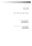
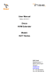
K434-1S/K434-1W/K434-1A
rev. 1.2
SDLink/LC, SDLink/DM SDLink/AU
Cat5-extender
for Keyboard, VGA, Mouse (KVM)
resolution up to 1280x1024
distances up to 50m
The CAT5 KVM Mini Extender allows you to remotely position your SuperVGA monitor,
keyboard and mouse up to 50 Metres from your PC System unit using a single Category 5
UTP/STP 4-pair cable.
Please read this manual before installing and operating the units. Please record the serial number, the date of purchase and your sales office in the space below. The serial number is located
on the backside of the units. These data would be important, if you ever need to repair one of
the parts.
CAT5 KVM Mini Extender
only remote access . . . . . . . . . . . . . . . . . . . . . . . . . K434-1S
with local and remote access . . . . . . . . . . . . . . . . K434-1W
only remote access, with serial/audio option. . . . K434-1A
serial number. . . . . . . . . . . . . . . . . . . . . . . . . . . . . . . . . . . . .
date of purchase . . . . . . . . . . . . . . . . . . . . . . . . . . . . . . . . . .
sales office . . . . . . . . . . . . . . . . . . . . . . . . . . . . . . . . . . . . . .
rev: December, 2006
page: 17
SDLink/LC, SDLink/DM SDLink/AU
rev. 1.2
K434-1S/K434-1W/K434-1A
Features
This product has a number of unique features that allow transparent remote operation of your
PC.
• Access your CPU up to 50 Meters away using a single CAT 5 twisted pair cable.
• Adjustable Video Equalisation - Compensates for loss of image quality due to cable
length
• Fully buffered signals to ensure consistent remote operation of you PC
• PS/2 keyboard and PS/2 mouse emulation allowing you to ‘Plug & Play’ - Intelligent
keyboard and mouse emulation ensures the PC boots and operates correctly under all
possible circumstances as well as allowing ‘Plug & Play’ initialisation of the remote
keyboard and mouse.
Operation
The Mini Extender is simple to operate and works with all operating systems - no software is
required. Just connect the units up as described and you’re ready to work. Complete keyboard
and PS/2 mouse emulation allows you to ‘Plug & Play’. Your PC will boot even if the remote
end of the link is not powered or the keyboard and / or mouse are disconnected.
Mounting arrangement
fig.: 2 - schematic installation arrangement
page: 18
rev: December, 2006
K434-1S/K434-1W/K434-1A
rev. 1.2
SDLink/LC, SDLink/DM SDLink/AU
Technical data
power supply
local unit
remote unit
:
:
from PC
9V DC Regulated, 1000mA, Floating Output
interfaces
monitor
:
keyboard
mouse
:
:
serial (only SDLink/AM)
audio (only SDLink/AM)
:
:
VGA, SVGA, XGA, RGB
resolution up to 1280x1024 NO Plug&Play!
IBM-PS/2 (AT with adaptor)
IBM-PS/2 Two Button, Microsoft Intellimouse
Logitech 3-Button PS2
transparent with handshake up to 19200 BAUD
bidirectional, virtual CD-quality 38,4kHz, 16 Bit
interconnect cable
(not in schedule of parts)
max. distance
:
:
simplex S-UTP Cat5 4x2xAWG24, e.g. type 402-0J or
wiring according EIA/TIA
up to 50m (app. 160 ft)
dimensions
weight
length/width/height
:
:
app.1.5 kg Complete package, 0,25 each unit
app. 110 x 80 x 25 mm: SDLink/LC (2 devices)
app. 110 x 80 x 44 mm: SDLink/DM + /AM (2 devices)
temperature operation
:
app. 10°C ... 45°C
Compatibility
To operate in various environments and with hardware from many manufacturers, this product
has a number of specific features, and has been tested with a wide variety of hardware. However, it is impossible to guarantee correct operation with every keyboard, monitor, mouse and
motherboard currently on the market.
The CAT5 KVM Mini Extender is compatible with the following equipment:
• System Unit:
• Keyboard:
• PS/2 Mouse:
• Monitor:
PC/AT, PS/2 and 100% compatible clones.
PC/AT, Enhanced Keyboard. Some older XT/AT autosensing keyboards may not be compatible
Standard PS/2 Mouse, Microsoft Intellimouse,
Logitech 3-Button PS/2 Mouse
VGA, Super VGA, XGA, RGB (Sync-on-Green)
Note: If your PC does not have a PS/2 style mouse port, the Mini Extender may be connected
to a serial port of your PC via an additional mouse protocol converter (MDAPT).
rev: December, 2006
page: 19
SDLink/LC, SDLink/DM SDLink/AU
rev. 1.2
K434-1S/K434-1W/K434-1A
Connectors and cables
pinout is valid for both, local and remote unit
To connect the local unit to the PC, please use only the supplied combined system cable.
12345-
red signal
green sinal
blue signal
GND
n.c.
678910-
red GND
green GND
blue GND
n.c.
GND
123-
MOUSE DATA
n.c.
GND
456-
n.c.
MOUSE CLCK
n.c.
123-
KEYB DATA
n.c.
GND
456-
monitor/n.c.
KEYB CLCK
n.c.
1112131415
n.c.
n.c.
HSYNC
VSYNC
n.c.
VGA OUT
HD15 female
MOUSE OUT
6p miniDIN female
KEYB IN/OUT
6p miniDIN female
page: 20
rev: December, 2006
K434-1S/K434-1W/K434-1A
rev. 1.2
SDLink/LC, SDLink/DM SDLink/AU
Cat5 interconnect cable
The Local and Remote Units are interconnected by industry standard
structured cabling (Category 5 UTP/STP, 4-pair) terminated with RJ45
connectors. This cable is not supplied with the Mini Extender.
The cable used should be solid trunk cable. Stranded patch cable will result in poor quality video.Note: That failure to wire the twisted pairs correctly will impair the video quality dramatically and / or prevent correct
operation.
The Mini Extender is designed for use up to a maximum cable length of
50 Meters. At this length the video quality should still be acceptable even
at a screen resolution of 1280x1024 (75Hz).
Although a single continuous length of interconnect cable is preferable,
operation is possible through multiple patch panels. However, the more
patch panels the cable is routed through, the greater the chance of video signal degradation.
Using other types of structured cabling
Although specified for Category 5 cabling, the Mini Extender system has
been tested on CAT 3 cable and on pairs within a 25-pair UTP trunk cable.
Getting started
The CAT5 KVM Mini Extender consists of a Local and a Remote Unit interconnected by a single structured cable that carries all the necessary signals. The Local Unit is connected to the
PC’s keyboard, VGA and PS/2 mouse ports. The keyboard, monitor and mouse are connected
directly to the Remote Unit, which is powered by a power supply whilst the Local Unit is powered by the PC.
We recommend that the complete system is tested in one room before permanent installation.
If a long interconnect cable is not available, use a patch lead to test basic unit operation with
your PC.
Step 1: Setting the Cable Length Switch
The Remote Unit contains video equalisation circuitry which compensates for loss in image
quality experienced when driving over long cables. Please note that for all practical purposes,
cable equalisation cannot be exact – the remote image will never be as sharp as the original.
To set the correct level of equalisation there is a DIP Switch located on the bottom of the Remote Unit.
The DIP Switch should be set as follows: (DIP Switch 2: Please see section regarding Scroll
Lock Reset.)
rev: December, 2006
page: 21
SDLink/LC, SDLink/DM SDLink/AU
rev. 1.2
K434-1S/K434-1W/K434-1A
DIP-Switch 1:
Cable Length
(Metres)
0 - 25
25-50
Remote Unit
Dip Switch 1
Dip Switch 1 - OFF (Default)
Dip Switch 1 - ON
Tip: If you are at the top end of a cable length range (say 23m) and are using high resolution
(1024x768 or more), you may achieve better video quality be selecting the next cable length
range.
If you are conducting a test in one room prior to final installation, set the switch as appropriate
for the test cable length.
Step 2: Connecting Up
• Switch off your PC and power up the Remote Unit by connecting the mains adapter
and switching it on. Only use the mains adapter supplied.
• Connect all remaining cables as shown in Figure 2.
• Power on your PC and check that the keyboard operates correctly. Boot an operating
system (such as Windows) or application you intend to use. Check that the mouse
functions (if required).
• Check that the link integrity LED on the local unit flashes on and off.
Operation
The Remote Unit (when installed in its final location) may be left permanently powered up.
Keyboard & Mouse Emulation
The CAT5 KVM Mini Extender uses a microprocessor to emulate the keyboard and mouse.
This means that a keyboard and / or mouse do not have to be connected to the Remote Unit for
your PC to boot. In fact the PC will boot with only the Local Unit connected.
This feature ensures that your PC will always operate regardless of whether the Remote Unit is
actually connected or powered. The remote keyboard and mouse may be plugged in and out at
any time. In addition, emulation allows multiple Local/Remote Units to be used by simply
swapping over CAT 5 cables.
page: 22
rev: December, 2006
K434-1S/K434-1W/K434-1A
rev. 1.2
SDLink/LC, SDLink/DM SDLink/AU
‘Scroll Lock’ Reset
The Mini Extender re-defines the <SCROLL LOCK> key as a device reset. Whenever you reconnect a keyboard or mouse to the Remote Unit, press <SCROLL LOCK> to reinitialise
them. You should also press <SCROLL LOCK> should the keyboard or mouse ever lock up.
If you are processing the ‘Scroll Lock Reset’ at the local console on a device with local access
(K434-1W), please press <SCROLL LOCK> twice!
If you are using the Mini Extender together with an application or server switch that requires
the scroll lock key, the device reset function may be disabled and the normal scroll lock function restored.
For normal scroll lock key operation set DIP Switch#2 on the Remote Unit to ON (default off)
Link Integrtiy LED
An LED on the Local Unit provides visual indication that the unit is powered and the data link
is operating correctly.
When the PC is switched on the LED will light to show that the unit is powered. After the system has finished it’s initial BIOS boot sequence the LED will start to flash on and off to indicate that it is communicating correctly with the Remote Unit.
If the Remote Unit is powered down (or is not currently connected) the Link Integrity LED will
remain lit and not flash.
Correction of Out of Sync PS/2 Mouse (Null Mouse Command)
This feature allows recovery should the mouse go out of sync (pointer jumping all over the
screen) without having to reboot the system.
This condition has two possible causes:
• The PS/2 mouse itself is out of sync with Mini Extender.
• The PC’s mouse port has got out of sync with the Mini Extender.
Use the following procedure to recover the mouse:
• Press and release the <SCROLL LOCK> key (twice on the local console) to directly
reset the keyboard and mouse.
• Check if the mouse is now operating correctly.
If the mouse is still erratic, issue the following Null Mouse Command to re-synchronise the
mouse:
rev: December, 2006
page: 23
SDLink/LC, SDLink/DM SDLink/AU
rev. 1.2
K434-1S/K434-1W/K434-1A
• Press and hold down the left and right mouse buttons.
• Press and release the <SCROLL LOCK> key (and then let go of the mouse buttons).
• Check if the mouse is now operating correctly. If not, repeat steps 3 and 4 up to three
times.
The Null Mouse Command sends a single null byte to the PS/2 mouse port. By issuing this
command up to three times the Mini Extender mouse reports will become re-synchronised with
the order expected by the PC. Ordinarily, the mouse should never go out of sync. However, this
command provides a recovery mechanism avoiding the need to reload the mouse driver or reboot the machine should this condition occur.
Note: Issuing the Null Mouse Command when the mouse is operating correctly will cause
it to go out of sync (unless the mouse driver is auto-correcting).
Dual access (K434-1W only)
Usually, the picture is displayed on both connected screens. Pressing any key on a keyboard or
moving the mouse or pressing a mouse button will switch the access to the place, where the action happened. Unless there is any input on the keyboard or mouse movement, the access is
locked. The access is locked until there is no longer input nor movement for at least 2 seconds.
Note: Using normal mice (with a trackball on the bottom), there are possible circumstances,
where the mouse is placed disadvatageously, where the mouse sends, depending on small vibrations, continously data to the PC. Due to this, there is no access possible from the other console. In this case please move the mouse for a short way, to reach a stable position. To prevent
this, or in cases with strong vibrations, please unplug the mouse and reseat it only during access.
The local uconsole can force a ‘privat mode’ where no access through the remote unit is possible and where the screen on the remote side is blanked. This feature may be helpful for maintenance reasons. To reach the ‘private mode’ please press <SCROLL LOCK> on the local Unit.
Press <SCROLL LOCK> againfor releasing the ‘private mode’. If you set DIP Switch 2 to ON
the scroll lock key will revert to normal and you will not have access to private mode.
On PC boot (or remote power on/reset) the local console is active.
page: 24
rev: December, 2006
K434-1S/K434-1W/K434-1A
rev. 1.2
SDLink/LC, SDLink/DM SDLink/AU
Addendum for devices With Audio/Serial Option installed
The Audio/Serial Option consits of daughter boards which allow bi-directional stereo audio
and a full-duplex serial data link to be sent across the regular interconnection cable in addition
to keyboard, mouse and VGA/DVI video.
• To set up your video, keyboard, mouse follow the instructions in the user guide.
• To set up the extender’s audio and serial link, please follow all of the instructions detailed in this addendum. If you have any questions, contact Technical Support.
serial link:
serial speed
Flow Control
AUDIO link:
Description
Local Unit Connectors
Remote Unit Connectors
Microphone Support
:
:
Any <= 19,200 Baud, Format Independent
RTS, CTS, DTR, DSR are sent across link
:
Bi-directional stereo audio link, Digitised virtually CD
quality audio (16-bit, 38.4KHz), Line-Level (5 Volts
Pk-Pk maximum) at 47K
2 x 3.5mm stereo jack socket (Line In & Line Out)
2 x 3.5mm stereo jack socket (Line/Mic In & Line Out)
A microphone may be connected to the Remote Unit
Pullup resistor provides bias for condenser microphone
Option to set microphone amplification to +17dB
:
:
:
Connectors and cables
SER IN
DB9 female
SER OUT
DB9 male
to CPU
DB9 female
rev: December, 2006
12345-
n.c.
RxD
TxD
DTR
GND
6789-
DSR
RTS
CTS
n.c.
12345-
n.c.
RxD
TxD
DTR
GND
6789-
DSR
RTS
CTS
n.c.
12345-
n.c.
RxD
TxD
DTR
GND
6789-
DSR
RTS
CTS
n.c.
to device
DB9 male
page: 25
SDLink/LC, SDLink/DM SDLink/AU
rev. 1.2
K434-1S/K434-1W/K434-1A
Serial Interface - Set Up and Operation
No setting up or user adjustments are required. Please note that on the dual access model, the
serial link is always active
Please bear in mind that the Remote Unit’s serial port is wired as DTE (i.e. the same as that on
a PC). A serial Touchscreen may be plugged directly into the Remote Unit.
Serial Interface – Handling Multiple Serial Devices
The extender’s serial interface transmits/receives six signals (3 signals in each direction). Normally four of these signals are used for hardware handshaking (in addition to TX & RX).
However, because each handshaking line can support signals up to 19,200 Baud it is possible
to configure the serial interface to handle up to three simple 2-wire (Tx/Rx only) serial links.
To do this you will need to construct a custom breakout cable. Please contact technical support
for further information.
Audio Interface - Set Up and Operation
The audio interface is line-level and is designed to take the output from a sound card (or other
line-level) source and be connected to a set of powered speakers at the other end of the link.
Stereo audio may be transmitted either way across the link (simultaneously). No set up is required unless a microphone is connected to the remote unit.
Connect up the extender as follows:
• Take the line-level output from your sound card (green connector) and connect to ‘Line In’ on the extender.
• A set of powered speakers may be connected directly to ‘Line Out’ at the opposite end
of the link.
Audio Interface – Using a Microphone
A microphone may be plugged into the ‘Line In’ connector on the Remote Unit.
There are two ways of setting up a microphone:
• The Local Unit’s ‘Line Out’ connection should normally be wired to the microphone
input (Red) on your sound card. The sound card should then be set up to provide additional amplification (+20dB). This is the preferred connection method.
• Alternatively, the Remote Unit itself can provide microphone amplification. To set
this, open up the Remote Unit and locate the jumper labelled ‘MIC’ on the daughterboard. Connect this jumper across the pins. The Local Unit’s ‘Line Out’ connection
should then be wired to ‘Line In’ (Blue) on your sound card.
If your microphone is already amplified, follow the second method but DO NOT install the
amplification jumper in the Remote Unit.
page: 26
rev: December, 2006
K434-1S/K434-1W/K434-1A
rev. 1.2
SDLink/LC, SDLink/DM SDLink/AU
Troubleshooting
Keyboard
•
º
º
º
The PC boots fine with no error messages but the keyboard does not work at all
Cable is loose, re-seat keyboard cable and press <SCROLL LOCK>
Wrong cable plugged in, keyboard and mouse cables reversed.
Try a different model of keyboard. If the new keyboard works then original one may
be incompatible (some older auto-sensing units may not work with this product).
• Wrong or missing characters from those typed.
º The keyboard may be in the wrong mode. Press ‘Scroll Lock’ to reset it.
º Power down and reboot the entire system.
• The PC always comes up with ‘Keyboard Error ’
º If the system appears to work fine after pressing F1 (or ESC) adjust your BIOS set-up
so that the PC does not test the keyboard.
PS/2 Mouse
•
º
º
º
º
º
A mouse cursor appears on the screen, but the mouse does not work
Press <SCROLL LOCK> on the keyboard to reset the mouse.
Cable is loose, re-seat mouse cable and press <SCROLL LOCK> on the keyboard
Wrong cable plugged in, keyboard and mouse cables reversed.
Try a different model of mouse.
Unplug the CAT5 cable and power-cycle the remote unit.
• The system does not detect a PS/2 mouse, or the application cannot find the
mouse.
º Wrong cable plugged in, keyboard and mouse cables reversed on Local Unit.
º Cable is loose, re-seat mouse cable between Local Unit and CPU and press <SCROLL
LOCK> on the keyboard
º Ensure that the Local Unit is connected to the PC keyboard port to provide power.
º Reboot PC.
•
º
º
º
The mouse movement is erratic
Press <SCROLL LOCK> to reset the remote keyboard and mouse.
Issue the Null Mouse Command (see Operation Section for details)
Try installing a Microsoft Intellimouse mouse driver that can automatically correct out
of sync mice.
º Reload the application and/or reboot the PC. If this problem persists call technical support.
º If using in conjunction with a Server Switch, command the switch to reset the mouse.
•
º
º
º
Neither the keyboard or mouse operate, or have locked up
Reset Keyboard and mouse by pressing <SCROLL LOCK> a number of times.
Reset PC and the Remote Unit.
Check power to Remote Unit.
rev: December, 2006
page: 27
SDLink/LC, SDLink/DM SDLink/AU
rev. 1.2
K434-1S/K434-1W/K434-1A
Video
•
º
º
º
The picture is not sharp & is very smeary
Video compensation incorrectly set. - See installation section.
UTP/STP interconnection cable is wired incorrectly. See wiring chart above
Check that the UTP / STP is solid trunk cable + all connectors/patch cables are correct.
• Each character has separated into overlapping red, green & blue pixels; (the effect is like looking through 3D glasses).
º Check that the UTP / STP is solid trunk cable.
º Check patch panels for poor or incorrect connections
º Check the compensation jumper settings.
º UTP/STP interconnection cable is wired incorrectly. See wiring chart above.
• My LCD panel does not display a picture. If I connect a normal monitor everything is OK!
º LCD panels have very stringent timing requirements because they re-sample the video
signal. When operating over a long cable some video signal timings may become skewed causing display problems with the occasional LCD panel. Try reducing the vertical refresh rate. This will have no effect on the quality of the video because LCD
panels do not flicker.
• The monitor sometimes loses sync causing it to go blank for a second or two
º This occurs if your electrical power system is very noisy (particularly ground). Do not
run the interconnection cable near to power lines.
• Video only required, but no picture appears
º The probable cause is that the Local Unit is not powered. The Local Unit draws its power from the PC’s keyboard port, so the PC keyboard cable must be connected even if
video only operation is required.
º Consult technical support if you cannot do this as there are other options for powering
the Local Unit
• A constant vertical wobble appears down the screen (interference).
º The interconnection cable could be located too close to a source of very strong mains
borne interference, re-route cabling if possible.
º If interference is from strong signals from a nearby broadcast transmitter a beat pattern
will appear. Change the vertical refresh rate slightly, such as from 60Hz to 70Hz.
• The picture on the monitor is black & white not colour
º Your system needs to see a Monitor ID code to boot into the correct video mode. Please contact technical support for details on how to correct this.
• Microsoft Windows or NT will only boot into a low-resolution graphics mode.
º The problem could be Monitor ID. See above.
º If your graphics card supports VESA DDC (Display Data Channel) configure the
graphics driver by explicitly telling it which make and model of monitor you have rather than using DDC.
page: 28
rev: December, 2006
K434-1S/K434-1W/K434-1A
rev. 1.2
SDLink/LC, SDLink/DM SDLink/AU
General Questions
• Is it possible to use a cable length of more than 50 Metres?
This product has been designed to produce acceptable results with Super VGA resolutions at the maximum cable length. It may be possible to run up to 100m at the standard VGA resolution (640x480). However, we cannot guarantee that this will work in
every instance.
• Can Mini Extenders be chained to allow operation over more than 50 Metres?
No this is not recommended. If you need to go further you can purchase a replacement
long-distance Remote Unit which will allow you to drive up to 300 Metres.
• Which cable is better UTP or STP?
UTP cable will give the best quality video over long distances because it has less capacitance per unit length. However, STP may be a better choice in electrically noisy environments (but the cable screen must be connected to both the Local and Remote
Units in order to be effective).
• When using UTP what is the best way to ensure the system does not suffer from
any interference?
This product is designed to withstand high levels of interference whilst using UTP
over long distances. To further reduce the potential for interference consider the following:
Ensuring that the computer, remote monitor and remote PSU are all connected on the
same mains phase.
º Ensuring that the AC voltage across the mains grounds (at the local PC & remote monitor) is less than 1V.
º Using a clean earth system (if your site has one installed).
º Routing the interconnection cable away from other cables.
º Trying STP cable if you think noise could be a problem. Remember to ensure that the
cable screen is connected to both the Local & Remote unit, otherwise the interference
may become worse!
º For heavy industrial environments we recommend another model of extender.
• Can the CAT5 KVM Mini Extender be used between buildings?
The Mini Extender does not have line isolation. Therefore, operation between buildings is not recommended.
• Can the Mini Extender be used with RGB (Sync-On-Green) video?
Yes, it should operate fine. If you encounter any problems please contact technical
support.
• Is a Rack Mount kit available?
No. There are other alternative CAT5 Extender products available in the range which
are rack mountable.
rev: December, 2006
page: 29
SDLink/LC, SDLink/DM SDLink/AU
rev. 1.2
K434-1S/K434-1W/K434-1A
• Can I use multiple Local or Remote Units by swapping (switching) the UTP cable
over?
Yes, because the Mini Extender has full emulation you can swap cables between units
and make in effect a distributed matrix switch. After swapping the cable, press
<SCROLL LOCK> sto resynchronise.
• Can I connect the Mini Extender system into my network?
No. Although the extender uses the same cable it cannot be connected into your network in any way.
CAT5 KVM Mini Extender Version Numbers
A version number is located on the rear of the Local and Remote Units: Version Number Format: xxSyy. Where xx is the hardware revision & yy is the firmware revision
Always quote the full version number when contacting technical support. The firmware may be
updated by changing a ROM chip in either the Local or Remote unit.
page: 30
rev: December, 2006
K434-1S/K434-1W/K434-1A
rev. 1.2
SDLink/LC, SDLink/DM SDLink/AU
Delivery informations
Mini Cat5 Extender without local access
order notation
order number
:
:
SDLink/LC
K434-1S
Mini Cat5 Extender with local access
order notation
order number
:
:
SDLink/DM
K434-1W
Mini Cat5 Extender without local access, with serial/audio support
order notation
order number
:
:
SDLink/AU
K434-1A
schedule of parts supplied:
•
•
•
•
•
•
1
1
1
1
1
1
Mini Extender Local Unit
Mini Extender Remote Unit
9V 1000mA DC Regulated Power Supply (Universal Input – Isolated Output)
IEC Power Cord
CPU Cable Assembly (1 Metre)
User Manual
Interconnect cable between local interface and remote interface is not included. The Mini Extender has been tested with all major makes of CAT 5 cable including BICC-VERO, Mohawk,
AT&T.
Caution: Only use the power supply originally supplied with this product.The Mini Extender has a PS/2 type keyboard connector. If your system uses the AT type 5-pin DIN connectors
adapters will be required. If your PC does not have a PS/2 mouse port, please refer to the note
under the ‘Compatibility’ section of this manual.
Order notation accessories
junction cable:
plug-mounting (incl. plug set) :
rev: December, 2006
Cat5 simplex, 4x2xAWG24
Cat5 duplex / 2x Cat5 simplex
402-0J
402-1A
page: 31
SDLink/LC, SDLink/DM SDLink/AU
rev. 1.2
K434-1S/K434-1W/K434-1A
CE-declaration of conformity
This is to certify that, when installed and used according to the instructions in this manual, together with the specified cables and the maximum cable length of 3m, the Units:
K434-1S, K434-1W, K434-1A
are shielded against the generation of radio interferences in accordance with the application of
Council Directive 89/336/EEC as well as these standards:
EN 55022: 1999 Class A
EN 55024: 1999
IEC 61000-4-2: 2001
IEC 61000-4-3: 2001
IEC 61000-4-4: 2001
EN 61000-3-2 2001
EN 61000-3-3 2002
The device was tested in a typical configuration.
Oberteuringen, December 6th, 2006
The management
This equipment has been found to comply with the limits for a Class A digital device, pursuant
to Part 15 of the FCC Rules. These limits are designed to provide reasonable protection against
harmful interference when the equipment is operated in a commercial environment. This
equipment generates, uses, and can radiate radio frequency energy and, if not installed and
used in accordance with the instruction manual, may cause harmful interference to radio
communications. Operation of this equipment in a residential area is likely to cause harmful
interference in which case the user will be required to correct the interference at his own
expense.
Disclaimer
While every precaution has been taken in the preparation of this manual, the manufactorer assumes no resposibility for errors or omissions. Neither does the manufacturer assume any liability for damages resulting from the use of the information contained herein. The manufacturer
reserves the right to change the specifications, functions, or circuitry of the product without notice.
The manufacturer cannot accept liability for damage due to misuse of the product or due to
other circumstances outside the manufacturer’s control. And the manufacturer will not be responsible for any loss, damage, or injury arising directly or indirectly from the use of this
product.
page: 32
rev: December, 2006