1
USER MANUAL
BL IDENTHANDHELD
HARDWARE
S1585/01
Technical Reference Manual
BL ident-Handheld
TURCK-RFID-Handheld-Computer
Version 1.0
Hans Turck GmbH & Co.KG
Regulatory Notices
FCC Part 15 Class A
This equipment has been tested and found to comply with the limits for a Class A digital device,
pursuant to Part 15 of the FCC Rules. These limits are designed to provide reasonable protection against
harmful interference when the equipment is operated in a commercial environment. This equipment
generates, uses, and can radiate radio frequency energy and, if not installed and used in accordance with
the instruction manual, may cause harmful interference to radio communications. Operation of this
equipment in a residential area is likely to cause harmful interference in which case the user will be
required to correct the interference at his own expense.
FCC Part 15.225 (15C)
Registration Number: RYJJETTRFID-1356
Canadian Department of Communications
This digital apparatus does not exceed the Class A limits for radio noise emissions from digital
apparatus set out in the Radio Interference Regulations of the Canadian Department of
Communications
Le present appareil numerique n’emet pas de bruits radioelectrique depassant les limites applicables
aux appareils numeriques de la class A prescrites dans le Reglement sur ie broullage radioelectrique
edicte par le ministere des Communications du Canada.
Industry Canada RSS-210 6.2.2(e), 2001
Certifications
CENELEC
EMI Standards:
•
EN 55022:1998 (CISPR22), Class A
•
EN 55022/IEC 61000-4-6
•
ETSI EN 300 330-2: 2001
EMC Standards:
•
EN 55024: 1998
•
ETSI EN 301489-1: 2002
•
ETSI EN 301489-3: 2002
~
EN/IEC 61000-4-2
~
EN/IEC 61000-4-3
~
EN/IEC 61000-4-4
Safety Standards:
• EN
60950: 2000
Hans Turck GmbH & Co.KG • Witzlebenstraße 7 • 45472 Mülheim/Ruhr • Germany • Tel. +49 (0)208 4952-0 • www.turck.com
v
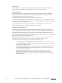
Warnings
Changes or modifications to this unit not expressly approved by the party responsible for regulatory
compliance could void the user's authority to operate the equipment.
Operation
Do not enable or utilize the RFID module while charging the unit. Operation of this nature is
likely to cause harmful interference.
Ne permettez pas ou n'utilisez pas le module de RFID tout en chargeant l'unité. L'opération de
cette nature est susceptible de causer l'interférence nocive.
No permita ni utilice el módulo de RFID mientras que carga la unidad. La operación de esta
naturaleza es probable causar interferencia dañosa.
Lassen Sie das RFID-Modul während des Aufladens des Geräts uneingeschaltet. Ein Betrieb
während des Aufladens verursacht mit groβer Wahrscheinlichkeit schädliche Störungen.
Electrostatic Discharge (ESD)
Electrostatic discharge (static electricity) can have unpredictable adverse effects on any
electronic device. Although the design of this product incorporates extensive ESD-related
precautions, ESD can still cause problems. It is good practice to discharge static by touching a
grounded metal object before inserting cards or connecting devices.
La descarga electrostática (electricidad estática) puede tener efectos nocivos imprevisibles en
cualquier dispositivo electrónico. Aunque el diseño de este producto incorpora precauciones
ESD-relacionadas extensas, la lata de ESD todavía causa problemas. Es buena práctica
descargar parásitos atmosféricos tocando un objeto puesto a tierra del metal antes de insertar
tarjetas o de conectar los dispositivos.
La décharge électrostatique (l'électricité statique) peut avoir des effets nuisibles imprévisibles
sur n'importe quel dispositif électronique. Bien que la conception de ce produit incorpore des
précautions ESD-connexes étendues, le bidon d'ESD posent toujours des problèmes. Il est dans de
bons habitudes de décharger la charge statique en touchant un objet au sol en métal avant
d'insérer des cartes ou relier des dispositifs.
Elektrostatische Entladung (statische Elektrizität) kann unvorhersehbare schädliche Wirkungen auf
elektronische Geräte haben. Obwohl das Gerät mit verschiedenen und umfangreichen ESD-bezogenen
Schutzeinrichtungen versehen ist, kann es doch zu ESD-Problemen kommen. Sorgen Sie vor dem
Einsetzen von Karten oder dem Anschluss von Geräten durch Berühren eines geerdeten
Metallgegenstands immer für eine statische Entladung.
Battery Replacement
CAUTION! There is a risk of explosion if you replace the NiMH battery with an incorrect type.
Only use the NiMH battery supplied with your unit or a replacement NiMH battery supplied,
recommended, or approved by TURCK, Inc.
PRECAUCIÓN! Hay un riesgo de la explosión si usted substituye la batería de NiMH por un
tipo incorrecto. Utilice solamente la batería de NiMH provista de su unidad o una batería de
NiMH del reemplazo provista, recomendada, o aprobada por TURCK, Inc.
ATTENTION! Il y a un risque d'explosion si vous remplacez la batterie de NiMH avec un type
incorrect. Utilisez seulement la batterie de NiMH fournie avec votre unité ou une batterie de
NiMH de remplacement fournie, recommandée, ou approuvée par TURCK, Inc.
VORSICHT! Bei Verwendung von NiMH-Batterien, die nicht von TURCK, Inc. geliefert, empfohlen
oder genehmigt wurden, besteht Explosionsgefahr! Benutzen Sie daher nur solche NiMH-Batterien,
die mit dem Gerät geliefert wurden, oder Batterien, die von TURCK, geliefert, empfohlen oder
genehmigt wurden.
vi
Hans Turck GmbH & Co.KG • Witzlebenstraße 7 • 45472 Mülheim/Ruhr • Germany • Tel. +49 (0)208 4952-0 • www.turck.com
Battery Disposal
Dispose of batteries in a safe manner. The following are general guidelines for the safe use and
disposal of NiMH batteries:
Replace a defective NiMH battery immediately as it could damage the unit.
Do not throw the NiMH battery it in trash that is disposed of in landfills as it contains heavy
metals. Recycle or dispose the NiMH battery of it as required by local ordinances or
regulations.
Do not disassemble, incinerate, short-circuit the NiMH battery or throw it into a fire. It can
explode and cause severe personal injury.
Excessive discharge damages a NiMH battery. Recharge the NiMH battery when your unit
indicates low battery power.
Disponga de las baterías de una manera segura. Los siguientes son pautas generales para el uso
seguro y la disposición de las baterías de NiMH:
Substituya una batería defectuosa de NiMH inmediatamente pues podría dañar la unidad.
No lance la batería de NiMH él en la basura que se dispone en terraplenes mientras que
contiene los metales pesados. Recicle o disponga la batería de NiMH de ella según los
requisitos de ordenanzas o de regulaciones locales.
No desmonte, no incinere, no cortocircuitos la batería de NiMH ni láncela en un fuego. Puede
estallar y causar daños corporales severos.
La descarga excesiva daña una batería de NiMH. Recargue la batería de NiMH cuando su
unidad indica energía de batería baja.
Débarassez-vous des batteries d'une façon sûre. Ce qui suit sont les orientations à l'utilisation
sûre et à la disposition des batteries de NiMH:
Remplacez une batterie défectueuse de NiMH immédiatement car elle pourrait endommager
l'unité.
Ne jetez pas la batterie de NiMH il dans le détritus qui est débarassé en remblais pendant qu'il
contient les métaux lourds. Réutilisez ou disposez la batterie de NiMH d'elle selon les exigences
des ordonnances ou des règlements locaux.
Ne démontez pas, n'incinérez pas, ne court-circuitez pas la batterie de NiMH ou ne la jetez pas
dans un feu. Il peut éclater et causer des blessures graves.
La décharge excessive endommage une batterie de NiMH. Rechargez la batterie de NiMH
quand votre unité indique la basse puissance de batterie.
Entsorgen Sie die Batterien auf eine sichere Weise. Die folgenden Regeln sind allgemeine Richtlinien
für den sicheren Gebrauch und die sichere Entsorgung der NiMH-Batterien:
Ersetzen Sie eine defekte NiMH Batterie sofort, da sie das Gerät beschädigen könnte.
Die NiMH-Batterien enthalten Schwermetalle. Werfen Sie die Batterien daher nicht in den
Hausmüll, der in normalen Deponien abgeladen wird, sondern entsorgen Sie sie gemäβ den
geltenden lokalen Vorschriften für Sondermüll.
Bauen Sie die Batterien nicht auseinander, zünden Sie sie nicht an, schließen Sie sie nicht kurz und
werfen Sie diese nichts ins Feuer. Sie können explodieren und ernste Verletzungen verursachen.
Eine übermäßige Entladung beschädigt eine NiMH-Batterie. Laden Sie die NiMH-Batterie neu,
wenn auf dem Geräte eine niedrige Batterieleistung angezeigt wird.
Servicing Information
When servicing the unit, the plug (BL ident connect cable) is the disconnect device. Simply
unplug the unit before servicing.
Al mantener la unidad, el enchufe (cable de BL ident connect) es el dispositivo de la desconexión.
Desenchufe simplemente la unidad antes de mantener.
En entretenant l'unité, la prise (câble de BL ident connect) est le dispositif de débranchement.
Débranchez simplement l'unité avant l'entretien.
Vor der Wartung des Geräts ist der Stecker (BL ident-Anschlussleitung) zu ziehen..
Hans Turck GmbH & Co.KG • Witzlebenstraße 7 • 45472 Mülheim/Ruhr • Germany • Tel. +49 (0)208 4952-0 • www.turck.com
vii
Contents
Chapter 1: Overview ........................................................................................................1-1
About this Manual ........................................................................................................................................ 1-1
About RFID .................................................................................................................................................... 1-1
About the BL ident-Handheld ...................................................................................................................... 1-2
BL ident-Handheld Features ..................................................................................................................... 1-2
Chapter 2: Getting Started ................................................................................................2-1
Front Components and Indicators .............................................................................................................. 2-1
Rear Components ......................................................................................................................................... 2-2
Compact Flash Slot Cover ........................................................................................................................... 2-3
Interface Connections ................................................................................................................................... 2-4
BL ident connect system............................................................................................................................. 2-4
DE-9 Connectors......................................................................................................................................... 2-4
6-Pin Modular Connector ........................................................................................................................ 2-5
Power Jack................................................................................................................................................... 2-5
Power Supplies, Cables and Adapters ....................................................................................................... 2-5
Chapter 3: Operation .......................................................................................................3-1
Power .............................................................................................................................................................. 3-1
Charging the Unit..................................................................................................................................... 3-1
Charge/Low Battery Indicator ............................................................................................................... 3-2
Power/Suspend Switch............................................................................................................................. 3-3
Power Management ................................................................................................................................... 3-4
Replacing Batteries/Battery Pack........................................................................................................... 3-5
Data Entry ...................................................................................................................................................... 3-6
Keypads ..................................................................................................................................................... 3-6
CE Keyboard ............................................................................................................................................. 3-7
Using the RFID Module ............................................................................................................................ 3-8
The Windows CE .NET Desktop ................................................................................................................ 3-9
Desktop Functions ..................................................................................................................................... 3-9
The Taskbar................................................................................................................................................. 3-9
The Start Menu .......................................................................................................................................... 3-10
SystemCF Folder ........................................................................................................................................... 3-10
Chapter 4: Configuration .................................................................................................4-1
The Control Panel.......................................................................................................................................... 4-1
Changing System Settings ....................................................................................................................... 4-3
Taskbar and Start Menu Settings ................................................................................................................ 4-4
Using the Compact Flash Slot...................................................................................................................... 4-5
Network Connections .................................................................................................................................. 4-6
Creating a Wired Ethernet Network Connection ................................................................................. 4-6
Creating Network Connection using a WLAN 802.11b Card ............................................................ 4-6
Setting Up Identification for Remote Networks .................................................................................... 4-7
Connecting to a Mail Server.................................................................................................................... 4-7
ActiveSync...................................................................................................................................................... 4-9
Initial Communication............................................................................................................................. 4-9
Subsequent Communication..................................................................................................................... 4-12
Persistent Registry......................................................................................................................................... 4-12
Saving Changes to the Registry................................................................................................................ 4-12
Resetting the Registry .............................................................................................................................. 4-13
Chapter 5: Troubleshooting ..............................................................................................5-1
Appendix A: Specifications ............................................................................................. A-1
Appendix B: Signal and Pin Assignments ........................................................................B-1
BL ident connect Cables.................................................................................................................................. B-1
1210 Series Modular Interface Cables .......................................................................................................... B-2
Modular Cable Adapters............................................................................................................................ B-3
Null Modem Cable ........................................................................................................................................ B-3
viii
Hans Turck GmbH & Co.KG • Witzlebenstraße 7 • 45472 Mülheim/Ruhr • Germany • Tel. +49 (0)208 4952-0 • www.turck.com
Appendix C: Keyboard Mapping Files ........................................................................... C-1
Keyboard Mapping Files Notes ..................................................................................................................
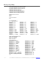
45-Key Key Map ............................................................................................................................................
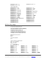
30-Key Key Map ............................................................................................................................................
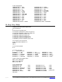
15-Key Key Map ............................................................................................................................................
C-1
C-2
C-3
C-4
Index.................................................................................................................................... I-1
List of Tables
Table 1-1: Tag Compatibility Chart ........................................................................................................... 1-2
Table 2-1: Front Components and Indicators .......................................................................................... 2-1
Table 2-2: Rear Components....................................................................................................................... 2-2
Table 2-3: Available Power Supplies, Cables and Adapters................................................................... 2-5
Table 3-1: Charge\Low Battery Indicator Functions............................................................................... 3-2
.Table 3-2: Modifier Key Actions ............................................................................................................... 3-7
Table 3-3: Desktop Functions ..................................................................................................................... 3-9
Table 3-4: Power Status Icons .................................................................................................................... 3-10
Table 4-1: Control Panel Functions............................................................................................................ 4-1
Table 7-1: Allowed Values in Key Map Files............................................................................................ C-1
List of Fig ures
Figure 2-1: Front Components and Indicators ......................................................................................... 2-1
Figure 2-2: Rear Components ..................................................................................................................... 2-2
Figure 2-3: Standard Compact Flash Slot Cover in Closed Position ..................................................... 2-3
Figure 2-4: Standard Compact Flash Slot Cover in Open Position........................................................ 2-3
Figure 2-5: Modified Compact Flash Slot Cover for Long Device Cards ............................................. 2-3
Figure 2-6: Sealed Compact Flash Slot Cover........................................................................................... 2-3
Figure 2-7: BL ident connect Interface Connector..................................................................................... 2-4
Figure 2-8: DE-9 Male Interface Connector .............................................................................................. 2-4
Figure 2-9: DE-9 Female Interface Connector........................................................................................... 2-4
Figure 2-10: 6-Pin Modular Interface Connector...................................................................................... 2-5
Figure 2-11: Power Jack............................................................................................................................... 2-5
Figure 3-1: Using 91708, 91709, and14375 Cables ................................................................................... 3-1
Figure 3-2: Using 1210 Series Cables ......................................................................................................... 3-1
Figure 3-3: Power Supply............................................................................................................................ 3-2
Figure 3-4: Charge/Low Battery Indicator............................................................................................... 3-2
Figure 3-5: Power/Suspend Switch........................................................................................................... 3-3
Figure 3-6: Changing Batteries .................................................................................................................. 3-5
Figure 3-7: Standard Keypad Layouts....................................................................................................... 3-6
Figure 3-8: 45-Keypad Multifunctional Key ............................................................................................ 3-6
Figure 3-9: CE Keyboard ............................................................................................................................ 3-7
Figure 3-10: RFID Read Range ................................................................................................................... 3-8
Figure 3-11: Windows CE .NET Desktop.................................................................................................. 3-9
Figure 3-12: Windows CE .NET Desktop Taskbar................................................................................... 3-9
Figure 3-13: Start Menu ............................................................................................................................... 3-10
Figure 6-1: Case Dimensions ...................................................................................................................... A-2
Figure 6-2: 91708 Cable (Male DE9) RS-232 Signal and Pin Assignments............................................ B-1
Figure 6-3: 91709 Cable (Female DE9) RS-232 Signal and Pin Assignments ....................................... B-2
Figure 6-4: 1210 Series Modular Cable Signal and Pin Assignments ................................................... B-2
Figure 6-5: CELAT-P Adapter ................................................................................................................... B-3
Figure 6-6: DE-9 Female to DE-9 Female Null Modem Cable................................................................ B-3
Hans Turck GmbH & Co.KG • Witzlebenstraße 7 • 45472 Mülheim/Ruhr • Germany • Tel. +49 (0)208 4952-0 • www.turck.com
ix
x
Hans Turck GmbH & Co.KG • Witzlebenstraße 7 • 45472 Mülheim/Ruhr • Germany • Tel. +49 (0)208 4952-0 • www.turck.com
Chapter 1: Overview
About this Manual
Intended for authorized developers with prior knowledge of Windows CE .NET and hand held PC
application development using eMbedded Visual C++ and Visual Studio .NET, this manual describes the
advanced features, operations and interface capabilities of TURCK’ BL ident-Handheld. It is not for use
by end-users.
Because the BL ident-Handheld is a highly customizable product with many optional configurations
and special keypad layouts, this manual only describes the standard features and operation of the
BL ident-Handheld. For custom configurations and special options, consult the appropriate
supplemental manual or addendum.
Unless otherwise stated, the operational characteristics described herein correspond to factory default
configurations and settings as shipped from TURCK. Wherever used herein, the term “BL identHandheld” applies to all models (except as noted).
It is beyond the scope of this manual to provide operating system tutorials or information about
commercial or customized BL ident-Handheldapplication programs and connected equipment.
This information should be available in the manuals that accompany those products.
About RFID
RFID (Radio Frequency IDentification) is a wireless communication technology that uses the RF portion of
the electromagnetic spectrum to transmit and receive information from EPC (Electronic Product Code)
tags. The tags can come in many shapes and sizes, such as disks, cards or paper labels (smart labels) and
can store a simple identification number or a sophisticated database.
RFID technology is based on the simple idea that a reader can activate an electronic circuit inside a tag
from a distance and exchange information. An integrated circuit inside the reader creates an alternating
current. This current generates an alternating magnetic field through the reader’s antenna that serves as a
power source for a RFID tag. This magnetic field interacts with the antenna in the tag, which in turn,
activates the tag’s integrated circuit causing the tag to create a digital signal, which contains an encoded
identifier number.
The tag then generates its own alternating magnetic field, which interacts with the reader’s alternating
magnetic field. A device inside the RFID reader senses the variations and converts this pattern to the
digital signal, which interprets the tag's identifier code.
Hans Turck GmbH & Co.KG • Witzlebenstraße 7 • 45472 Mülheim/Ruhr • Germany • Tel. +49 (0)208 4952-0 • www.turck.com
1–1
About the BL ident-Handheld
With its modern, ergonomic appearance and design, the BL ident-Handheld is the most recent addition to
TURCK' series of rugged hand held computers for industrial and commercial use. Its quick mount
connector system allows easy insertion and removal in cradle or vehicle mounts.
Designed for one-handed operation, the BL ident-Handheld features a powerful Microsoft Windows CE
.NET 4.2 operating system, Intel XScale Technology Processor, color sunlight readable display with
touch screen technology.
With its powerful 13.56 MHz RFID integrated reader and flip-out antenna, the BL ident-Handheld can read
and write most industry standard RFID tags within a 3.5 inch (80 mm) range making it ideal for
“contactless” payments, item tracking and data collection.
BL ident – Handheld Features
Rechargeable Battery Pack
The BL ident-Handheld comes with a rechargeable Nickel Metal Hydride (NiMH) battery pack that can
provide up to twelve hours of operating time on a full charge (depending on power management and
use). The NiMH technology used in the BL ident-Handheld has exceptional charge life without the
“charge memory” characteristic of conventional nickel cadmium batteries. Partially discharged batteries
or extended periods with the charger left connected will not adversely affect battery life or performance.
The BL ident-Handheld can also run on six AA Alkaline batteries.
Operating System
The BL ident-Handheld uses Windows CE .NET Professional 4.2 as its operating system
Processor
The BL ident-Handheld utilizes an Intel PXA255 processor with XScale technology at 200MHz
(400MHz optional) .The Intel PXA255 processor is a highly integrated, 32-bit RISC processor that
combines the efficiency of Intel design with the ARM v.5TE instruction set architecture.
Memory and Mass Storage
The BL ident-Handheld comes standard with 64MB of SDRAM and 64MB (approximately 16MB used
for operating system) of internal compact flash memory, which is expandable to 128MB. For removable
data storage or I/O cards, the BL ident-Handheld is equipped with a Compact Flash (CF) slot.
1– 2
Hans Turck GmbH & Co.KG • Witzlebenstraße 7 • 45472 Mülheim/Ruhr • Germany • Tel. +49 (0)208 4952-0 • www.turck.com
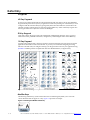
Displays
The BL ident-Handheld features a supertwist nematic liquid crystal 320 x 240 QVGA-TFT color
sunlight readable display with options for a touch screen and LED backlight.
Keypads
Standard keypad configurations for the BL ident-Handheld include 15-key, 30-key, and 45-key
elastomeric keypads and a 45-key membrane keypad. All standard keypad configurations have an option
for LED backlighting.
Indicators
The BL ident-Handheld has five programmable LED indicators that can provide a number of useful
functions including the state of keypad modifier keys. An additional LED indicates the charge and low
battery statuses.
Interface Capabilities
The BL ident-Handheld comes standard with one available serial port configured for RS-232.
Durability
The case is made of General Electric Xenoy, one of the most durable chemical resistant materials
available today.
Hans Turck GmbH & Co.KG • Witzlebenstraße 7 • 45472 Mülheim/Ruhr • Germany • Tel. +49 (0)208 4952-0 • www.turck.com
1–3
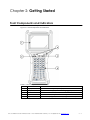
Chapter 2: Getting Started
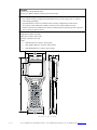
Front Components and Indicators
This section describes the components and indicators found on the front of the BL ident-Handheld.
Figure 2-1: Front Components and Indicators
Table 2-1: Front Components and Indicators
Item
Function
Description
1
Display
Supertwist nematic liquid crystal display with touch screen
2
Battery Indicator
Indicates low battery (red) status and charging (green) status
3
LEDs
Indicates use of the SHIFT, CTRL, 2ND ALT and CAPS modifier keys
4
On/Off Switch
Controls the Power, Suspend and Resume operations
5
Keypad
Standard 45-key keypad (30 and 15-key keypads not shown)
Hans Turck GmbH & Co.KG • Witzlebenstraße 7 • 45472 Mülheim/Ruhr • Germany • Tel. +49 (0)208 4952-0 • www.turck.com
2–1
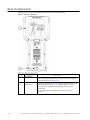
Rear Components
This section describes the components found on the rear of the BL ident-Handheld.
Figure 2-2: Rear Components
Item
2–2
Function
Description
1
RFID Module
The RFID Module attached to the rear of the unit can read RFID tags
in its storage position (show above) or swing out up to 180 degrees
for maximum range. See Figure 3-10.
2
Battery
Compartment
The battery compartment can store either the Nickel Metal Hydride
rechargeable battery pack or six AA Alkaline batteries. You can
access the battery compartment by lifting up and turning the
retaining clip.
For more information using batteries, see Battery-Powered
Operation.
Hans Turck GmbH & Co.KG • Witzlebenstraße 7 • 45472 Mülheim/Ruhr • Germany • Tel. +49 (0)208 4952-0 • www.turck.com
Compact Flash Slot Cover
The standard compact flash slot cover located on the top of the unit provides access to the compact flash
slot that stores memory and device cards. In addition to the standard cover, a modified cover and a sealed
cover are also available.
The modified cover (Figure 2-5) has a machined opening that allows you to easily insert and remove
devices cards that exceed 1.437 inches in height.
To remove the Torx screws requires an IP6 Torx (T6) driver.
For more information about inserting and removing memory and device cards, see Inserting and
Removing Cards.
Figure 2-3: Standard Compact Flash Slot Cover in Closed Position
Figure 2-4: Standard Compact Flash Slot Cover in Open Position
Fig ure 2-5: Modified Compact Flash Slot Cover for Long Device Cards
Hans Turck GmbH & Co.KG • Witzlebenstraße 7 • 45472 Mülheim/Ruhr • Germany • Tel. +49 (0)208 4952-0 • www.turck.com
2–3
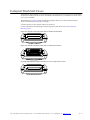
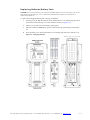
Interface Connections
This section describes the interface connectors found on the bottom of the BL ident-Handheld.
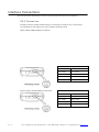
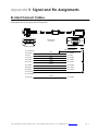
D E- 9 C on n ect ors
The DE-9 connectors emulate standard serial pin-out connections, and allow you to connect the BL
ident-Handheld to most desktop PCs using a standard null modem cable.
Figure 2-8: DE-9 Male Interface Connector
RS-232 Interface Pin-Outs
Pin 1 = DCD
Pin 6 = DSR
Pin 2 = RXD
Pin 7 = RTS
Pin 3 = TXD
Pin 8 = CTS
Pin 4 = DTR
Pin 9 = 11-18VDC Input
Pin 5 = Ground
Figure 2-9: DE-9 Female Interface Connector
RS-232 Interface Pin-Outs
Pin 1 = DTR
Pin 6 = DTR
Pin 2 = TXD
Pin 7 = CTS
Pin 3 = RXD
Pin 8 = RTS
Pin 4 = DSR/DCD
Pin 9 = 11-18VDC Input
Pin 5 = Ground
2–4
Hans Turck GmbH & Co.KG • Witzlebenstraße 7 • 45472 Mülheim/Ruhr • Germany • Tel. +49 (0)208 4952-0 • www.turck.com
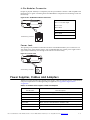
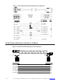
6-Pin Modular Connector
Despite its physical similarity to a telephone jack, the 6-pin modular connector is not compatible with
telephone lines or signals. Connecting the BL ident-Handheld to a telephone line will damage it and void
the warranty.
Figure 2-10: 6-Pin Modular Interface Connector
RS-232 Interface Pin-Outs
Pin 1 = 11-18 VDC Input
Pin 2 = CTS
Pin 3 = RTS
Pin 4 = TXD
Pin 5 = RXD
Viewed facing connector
Pin 6 = Ground
Power Jack
The optional power jack found on the bottom of the BL ident-Handheld enables you to connect an 11-18
VDC Input power supply battery charger, such as TURCK #14508. Use of other power supplies unless
approved by TURCK may cause damage to the unit and void the warranty.
Figure 2-11: Power Jack
Viewed facing connector
Power Supplies, Cables and Adapters
TURCK can provide the following optional power supplies, cable and adapters based on communication
and power requirements. For cable signal and pin assignments, see Appendix B: Signal and Pin
Assignments.
Table 2-3: Available Power Supplies, Cables and Adapters
TURCK
Part Number
14508
Part Description
11–18VDC Power Supply (North America Only) 1
91708
Black, 15-Foot BL ident connect Cable (DE-9 Male)
91709
Black, 15-Foot BL ident connect Cable (DE-9 Female)
1210-7-BK
Black, 7-Foot Coiled Modular-to-Modular Cable
1210-15-BK
Black, 15-Foot Coiled Modular-to-Modular Cable
14375
Black, 15-Foot Null Modem Cable (DE9 Female to DE9 Female)
CELAT-P
Modular Cable to DE-9 Cable Adapter
1. Use of other power supplies unless approved by TURCK may cause damage to the unit and void the warranty.
Hans Turck GmbH & Co.KG • Witzlebenstraße 7 • 45472 Mülheim/Ruhr • Germany • Tel. +49 (0)208 4952-0 • www.turck.com
2–5
Chapter 3: Operation
Power
The BL ident-Handheld comes with a rechargeable Nickel Metal Hydride (NiMH) battery pack that can
provide up to twelve hours of operating time on a full charge (depending on power management and
use). This battery is fully charged and installed in the unit when shipped. However, because some
battery dissipation occurs between the time when the unit ships and when you start using it, you should
charge the unit for approximately four hours before using it without the battery charger/power supply
connected.
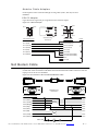
C h a rg i n g t h e Un it
The nickel metal hydride battery technology used in the BL ident-Handheld has exceptional charge life
without the “charge memory” characteristic of conventional nickel cadmium batteries. Partially
discharged batteries or extended periods with the charger left connected will not adversely affect battery
life or performance.
Warning! Do not enable or utilize the RFID module while charging the unit. Operation of this nature is likely to
cause harmful interference.
Note: Because the internal battery charger senses several conditions, including temperature, you should
charge the unit away from any known or potential heat sources. Units exposed to temperatures in excess of
110 degrees Fahrenheit during the charge cycle may experience incomplete charging and reduced
operating time per charge.
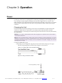
To charge the NiMH battery pack:
1. Depending on your configuration, plug the power jack of the battery charger/power supply
into the corresponding cables connector and/or adaptors as shown below.
Figure 3-1: Using 91708, 91709, and14375 Cables
Figure 3-2: Using 1210 Series Cables
Power Supply/Battery Charger
Hans Turck GmbH & Co.KG • Witzlebenstraße 7 • 45472 Mülheim/Ruhr • Germany • Tel. +49 (0)208 4952-0 • www.turck.com
3–1
2.
Plug the interface cable into the connector on the bottom of the BL ident-Handheld. If your
unit has a power jack receptacle on the bottom of your BL ident-Handheld, just plug the
power jack into that receptacle.
3.
Plug the battery charger/power supply into a power outlet. The Charge LED should turn on,
indicating that the batteries are charging (see Table 3-1).
Figure 3-3: Power Supply
4.
Once the battery is fully charged (approximately four hours), you can disconnect the A
power supply and run the BL ident-Handheld exclusively on battery power.
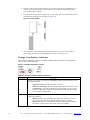
Ch a rg e/Low Ba t t ery Indicator
When using the NiMH battery pack, the CHARGE/LOW BAT LED will indicate the current battery
status as shown in the table below.
Figure 3-4: Charge/Low Battery Indicator
Table 3-1: Charge\Low Battery Indicator Functions
Function
CHARGE
Description
With the power supply connected, the CHARGE/LOW BAT LED will indicate one of
following conditions:
~
~
~
LOW BAT
3–2
High Power Charge—the LED will turn solid green
Fully/Near Full Charge—the LED will blink green about four times a second
Trickle Charge —the LED will blink green approximately once per second
when either the battery voltage and/or temperature of the battery assembly
are not within acceptable limits
With the power supply disconnected, the CHARGE/LOW BAT LED will indicate one
of following conditions:
~
Batteries are low— the CHARGE/LOW BAT LED will blink red once per
second when there is approximately 60 minutes of power remaining
~
Batteries are very low—the CHARGE/LOW BAT LED will turn solid red
when there is approximately 10 minutes of power is remaining
Hans Turck GmbH & Co.KG • Witzlebenstraße 7 • 45472 Mülheim/Ruhr • Germany • Tel. +49 (0)208 4952-0 • www.turck.com
Pow er/Su sp en d Switch
The On/Off switch is located above the keypad. Its function depends on the state of the BL identHandheld at the time the switch is pressed and on the length of time that the switch is depressed.
Operations that the Power switch can initiate are:
•
Power On
•
Power Off
•
Suspend
Power On
To power on the BL ident-Handheld:
5.
Press and hold the ON/OFF switch for one second.
6.
The unit should turn on and begin displaying the boot-up process.
7.
After approximately 20-25 seconds, the Windows CE .NET desktop should appear.
However, because there is no outward indication (such as a flashing LED) that the BL identHandheld is powered off or in Suspend mode, the BL ident-Handheldmay resume an active
application if it is indeed in a suspended state.
If the unit does not power up or you cannot select any items from the desktop, refer to the
“Troubleshooting” chapter for help.
Hans Turck GmbH & Co.KG • Witzlebenstraße 7 • 45472 Mülheim/Ruhr • Germany • Tel. +49 (0)208 4952-0 • www.turck.com
3–3
Power Off
To turn off the BL ident-Handheld, press and hold the ON/Off switch for approximately eight seconds.
This action will also terminate running applications and cease serial port operations).
Suspend Mode
Suspend mode allows you to suspend, but not terminate active applications. In this mode, the display
will turn off and the BL ident-Handheld will cease serial port operations. For battery-powered units,
use of Suspend mode also conserves battery power.
To place the unit in Suspend mode, press and release the ON/Off switch.
To take the BL ident-Handheldout of Suspend mode, either touch the screen or press and release any key.
The display will turn on and the BL ident-Handheld will resume running any suspended application, but
you must restart any serial port operations.
If you attempt to resume immediately after suspending the BL ident-Handheld or vice versa, the unit
will automatically delay three seconds before resuming or suspending.
Power Management
Battery-powered units can utilize a rechargeable Nickel Metal Hydride (NiMH) battery pack that has an
average operating time between ten and twelve hours on a full charge with power management and
approximately eight hours without power management. As with all battery-powered devices, the
operating time is completely dependent on the environment, device usage and the number and type of
power-drawing peripherals attached. The battery discharge rate in a full “Power Off” state is only slightly
higher to the self-discharge rate of the battery itself.
Note: Allowing the batteries to remain in a low or very low condition will cause the unit to enter Suspend
mode. In either case, you should save your work and recharge the unit as soon as possible
To lengthen the time between charges, you can perform the following actions:
•
Use external power for PC Card operations whenever possible — some PC Cards as well as
extended communication via the serial port, may require large amounts of power to operate,
and can quickly drain the batteries.
Limit the use of backlight—minimize backlight use when you are operating on battery power.
You can adjust the backlight timeout level through the Display Settings in the Control Panel or
on some units by using the keypad.
3–4
Shorten Auto-suspend time—the BL ident-Handheld is automatically set to suspend
operation to conserve battery power when you have not used the keyboard or the stylus
after three minutes. You can increase the Auto-suspend time by changing the Power settings
in the Control Panel.
Hans Turck GmbH & Co.KG • Witzlebenstraße 7 • 45472 Mülheim/Ruhr • Germany • Tel. +49 (0)208 4952-0 • www.turck.com
Replacing Batteries/Battery Pack
CAUTION! There is a risk of explosion if you replace the NiMH battery with an incorrect type. Only use the
NiMH battery supplied with your unit or a replacement NiMH battery supplied, recommended, or
approved by TURCK, Inc.
To replace the rechargeable battery pack or change AA batteries:
1.
Turn the power off. With the unit face down, pull the battery cover retaining clip up from its
recessed slot and turn the clip in a counter clockwise motion (see Figure 3-6).
2.
Lift the cover up and remove the batteries/battery pack.
3.
If the unit contains a NIMH battery pack, use the tab to lift up on the battery pack and then
out.
4.
Close the battery cover and turn the battery cover retaining clip clockwise to lock the cover.
Figure 3-6: Changing Batteries
Battery Pack Cover (opened)
Hans Turck GmbH & Co.KG • Witzlebenstraße 7 • 45472 Mülheim/Ruhr • Germany • Tel. +49 (0)208 4952-0 • www.turck.com
3–5
Data Entry
Keypads
45-Key Keypads
In order to provide the functionality of a full-sized keyboard with only 45 keys, the BL ident-Handheld
keypad must depart from PC-style key assignment conventions by making use of modifier keys. Units
configured with the standard 45-key keypad typically utilize five LED indicators (located above the
ON/OFF switch) to indicate the active state of keypad modifier keys. Units with 45-key keypads also
have keypad functions to adjust the contrast and backlight.
30-Key Keypad
Units with a 30-key keypad provide a full complement of alphabetical characters. Users can access
numeric characters, punctuation characters, navigation keys and backlight control via the SHIFT key.
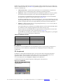
15-Key Keypad
Typically, units shipped with a 15-key keypad have custom keyboard layouts geared toward specific
applications that must be loaded onto the unit. To provide you a method of navigating and using
Windows CE .NET until you configure and map your keypad in the context of your application using
JETTkbtool. TURCK provides a template that shows the default functions (see figure below).
@
R
|
/
,
S
_ _ _ _ _
X
,
T
$
#
V=
W-
W M E N U B K L T
+
7
8
9
F 7
_____________ F 8
F 9
4
5
6
Figure 3-7: Standard Keypad Layouts
Modifier Keys
The following modifier keys (located on the bottom of a standard keypad) enable you to access the
various functions that can appear on a key. Figure 3-8 provides an example.
Figure 3-8: 45-Keypad Multifunctional Key
3–6
Hans Turck GmbH & Co.KG • Witzlebenstraße 7 • 45472 Mülheim/Ruhr • Germany • Tel. +49 (0)208 4952-0 • www.turck.com
Modifier keys take effect when first pressed and typically remain in effect until you press another key,
unless its another Modifier key (see Table 3-2). Optionally equipped units can use LEDs to indicate the
selection of a Modifier key.
•
CTRL and ALT Keys —operate in the same manner as on conventional PCs, except that by
default they have a one-time locking action to facilitate one-handed operation.
•
SHIFT Key—unlike conventional PC keyboards, the SHIFT key enables you to access symbols,
punctuation marks and navigation arrows rather than shift alphabetic keys to uppercase.
On standard BL ident-Handheld keypads, the functions and characters accessed via the SHIFT
key appear in the upper left of a key (shaded in gray in Figure 3-8).
By default, the SHIFT key has a one-time action. However, you can press the Shift key twice and
lock the keypad into Shift mode, wear each subsequent key press will only access characters that
appear in the upper left of a key. Pressing the Shift key a third time will release Shift mode.
•
2ND Key— shifts the numeric keys to corresponding function keys (1 = F1, 2 =F2, etc.) that are
found on conventional PC keyboards.
It also shifts other keys for punctuation, non-printing characters (such as Delete and TAB), and PC
key definitions (such as PageUp, PageDown, Home, Insert and Caps Lock).
On the standard BL ident-Handheld 45-key keypad, the functions and characters accessed via the
2nd key appear at the bottom of a key, (shaded in blue in Figure 3-8).
Like the Shift key, the 2ND key has a default one-time action and a locking mode (i.e., pressing the
2ND key twice will lock the keypad into 2ND mode).
.Table 3-2: Modifier Key Actions
Key Presses
Result
A
Lowercase “a”
Shift & A
Move cursor left one position
2ND & A
Delete Character
2ND & Caps Lock
Uppercase “A”
Key Repeat
By default, the BL ident-Handheld does not automatically repeat a key stroke when you hold down a
key. However, you can enable the key repeat function by configuring the Keyboard setting in the
Control Panel.
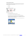
CE Keyboard
In addition to entering data through the keypad, you can also enter data by using the CE Keyboard.
This utility displays a keyboard on the screen to allow data entry via the Command Line or into
applications where “text accessibility” control has focus (i.e., text or combo box).
To use the CE Keyboard, select Programs > CeKeys from the Start menu.
To minimize the keyboard, click the keyboard icon that appears in the system tray
Figure 3-9: CE Keyboard
Hans Turck GmbH & Co.KG • Witzlebenstraße 7 • 45472 Mülheim/Ruhr • Germany • Tel. +49 (0)208 4952-0 • www.turck.com
3–7
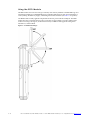
Using the RFID Module
The RFID module can read and write (up to 16k bits) most industry standard 13.56MHz RFID tags and
smart labels including for 13.56MHz RFID tag types including ISO-15693, Tag-It by Texas Instruments, I
Code by Philips, GemWave by TagSys, and PicoTag from Inside Contactless (see Table 1-1 for specifics).
.The RFID module is totally application dependent and derives power from the COM2 port. The RFID
module has a flip-out antenna that provides a read range of approximately 3.5 inches (90mm) with a
credit card size tag at 90 degrees (see illustration below). For RFID module application integration
information, contact TURCK.
Figure 3-10: RFID Read Range
3–8
Hans Turck GmbH & Co.KG • Witzlebenstraße 7 • 45472 Mülheim/Ruhr • Germany • Tel. +49 (0)208 4952-0 • www.turck.com
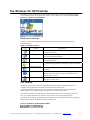
The Windows CE .NET Desktop
This section provides a brief overview of the functions that appear on the BL ident-Handheld desktop.
For information on how to change desktop settings, refer to Windows CE .NET help (Start > Help).
Figure 3-11: Windows CE .NET Desktop
Deskt op F u n ct i ons
You can access the following applications, functions and data entry utilities from the BL identHandhelddesktop:
Table 3-3: Desktop Functions
Icon
Function
Recycle Bin
Description
Use the Recycle Bin to restore deleted files or empty the bin to
create more disk space.
My Computer
Use My Computer to navigate and view the folders and files
stored on the BL ident-Handheld.
Inbox
Use the Inbox to send and receive e-mail by connecting to a
POP3 or IMAP4 server.
My Documents
The default storage location for documents, graphics, and other
files.
Microsoft WordPad
Use WordPad to create or edit text files that contain formatting
or graphics.
Internet Explorer
Use Pocket Internet Explorer to view Web pages. You will need
a modem or Ethernet card to connect to an Internet service
provider (ISP) or network.
PC Link
Use PC Link to make an ActiveSync, Bluetooth or other type of
connection to another device
T h e T a skb a r
The taskbar at the bottom of the BL ident-Handheld desktop displays the Start button, buttons of
currently running applications, the Status Area and the Show Desktop icon.
Tap the Start button to display the Start menu (see below for details). For each open application, a
button appears on the taskbar. Simply tap the button to activate the application.
The status area appears on the right and by default displays small icons for the input panel, current
time, power status and network connections. Tap an icon to activate the related program.
Tapping the Show Desktop icon minimizes active applications and redisplays the desktop. Tapping the
Keyboard icon displays the Input Panel menu for data entry.
Figure 3-12: Windows CE .NET Desktop Taskbar
Hans Turck GmbH & Co.KG • Witzlebenstraße 7 • 45472 Mülheim/Ruhr • Germany • Tel. +49 (0)208 4952-0 • www.turck.com
3–9
Power Status Icons
The BL ident-Handheld will display power status icons (Table 3-4) in the taskbar status area (Figure 312) to indicate power use, charging status and low battery conditions.
Table 3-4: Power Status Icons
Icon
Description
External AC power supply connected
Batteries are charging
Batteries are low —approximately 60 minutes or less of use remaining (the
CHARGE/LOW BAT LED will blink red once per second)
Batteries are very low—approximately 10 minutes or less of use remaining (the
CHARGE/LOW BAT LED will turn solid red)
The Start Menu
When you tap Start, the Start menu appears.
Figure 3-13: Start Menu
By tapping one of the menu’s icons (and not the name), you can:
•
Open programs that do not appear on the desktop
•
View a list of web sites added to your Favorites List
•
View recently accessed documents and images
•
Access the Control Panel, establish connections, or configure the Taskbar and Start Menu
•
View Help
•
Start an application using the Run command
•
Place the unit in Suspend mode
SystemCF Folder
The only folder that provides non-volatile (permanent) storage is the SystemCF folder. Information store
in other folder will be lost when you remove power from the BL ident-Handheld. You can however, have
the BL ident-Handheld automatically copy files from the SystemCF to other folders when booting up. See
Launching Files at Startup for more information.
3 – 10
Hans Turck GmbH & Co.KG • Witzlebenstraße 7 • 45472 Mülheim/Ruhr • Germany • Tel. +49 (0)208 4952-0 • www.turck.com
Chapter 4: Configuration
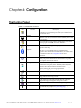
The Control Panel
The table below lists the available control panel functions on the BL ident-Handheld.
Table 4-1: Control Panel Functions
Icon
Function
Aux Switch
Description
For units with a second COM that supplies 5VDC output, use
this function to set the default power state (On or Off), and test
the connected devices.
Backlight
Use this function to adjust the backlight setting for the following
conditions: Line Active, Line Active Inactive, Battery Active and
Battery Inactive.
Battery Select
Select one of the following options to calibrate the power status
icons for proper use: NIMH, AC Line or Alkaline.
Beep Select
Use this function to change the frequency, volume and duration
properties of the beep.
Bluetooth Device
Properties
Use this function to scan for other Bluetooth devices and services
in the area. For use by Bluetooth cards manufactured by
companies other than Socket Communications, Inc. Socket cards
use a different control. See Using Bluetooth for more
information.
Certificates
Use this function to import, view or remove certificates, which
protect your personal information on the Internet, and protect
your computer from unsafe software.
CPU Speed
For units with 400 MHz processors, use this function to
determine the CPU speed (200 or 400 MHz) and mode (Turbo
and Non-Turbo) during runtime and cold boot-up.
Turbo Mode allows you to clock the processor core at a higher
frequency during peak processing requirements.
Date/Time
Use this function to adjust the date, time and time zone.
Dialing
Use this function to adjust the dialing location settings and
dialing patterns when using a modem.
Display
Use this function to adjust the backlight timeout, change the
background image or change the desktop color scheme.
Display Rotation
Use this function to rotate the screen 180 degrees (upside down).
Hot Keys
Use this function to assign functionality to the unit’s eight
programmable keys (requires Keyboard Mapping).
Hans Turck GmbH & Co.KG • Witzlebenstraße 7 • 45472 Mülheim/Ruhr • Germany • Tel. +49 (0)208 4952-0 • www.turck.com
4–1
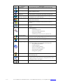
Icon
Function
Description
Input Panel
Use this function to adjust the settings for the input panel.
Internet Options
Use this function to set up connections, security settings and
internet related functions.
Keyboard
Use this function to change the repeat delay and repeat rate.
Network and
Dial-up Connections
Use this function to change network adapter settings and/or set
up identification for remote networks.
Owner
Use this function to enter the owner name, address, phone
numbers and network ID.
Password
Use this function to enable password protection and set a
password.
PC Connection
Use this function to enable direct connection to a desktop
computer
Power
Use this function to:
~
~
~
~
Check battery power
Set device to turn off when idle
Set up power schemes
Check the power levels of your system devices
Regional Settings
Use this function to change the appearance of region specific
information, such as date, time and currency.
Remove Programs
This function enables you to remove programs installed in RAM.
Storage Manager
This function enables you to perform the following tasks:
•
View partition information
•
Format a partition
•
Create or delete a partition
•
Mount or dismount a partition
•
Scan and repair a partition.
•
Defragment a partition
4–2
Stylus
Use this function to recalibrate the touch screen and adjust the
stylus double-tap rate.
System
Use this function to view system information, change the RAM
(Program/Storage memory) division, change the device name
and change the device description..
VComAdj
Use this function to minimize screen flicker and adjust contrast.
Hans Turck GmbH & Co.KG • Witzlebenstraße 7 • 45472 Mülheim/Ruhr • Germany • Tel. +49 (0)208 4952-0 • www.turck.com
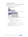
C h a n g i n g Syst em Settings
Any time you make changes through the Control Panel (such changing the time zone), you must also
update the persistent registry to store the changes in internal compact flash memory to make the
changes permanent.
For example, to change the time zone and save the changes to the registry:
1.
Select Start > Settings > Control Panel.
2.
On the Control Panel, double-tap Date/Time. The Date/ Time Properties dialog box appears.
You can now set the date, time and time zone.
3.
To adjust the Current Time, use the scroll bars to increase or decrease the value, or tap hours,
minutes, seconds or AM/PM indicator to set the values individually.
4.
To select the Time Zone, use the corresponding list.
5.
To adjust the Date, either:
Tap the arrows on the calendar to select the previous/next month
Double-tap the month or year to select it from a list
Tap a day to select it
6.
To adjust the clock automatically for daylight savings, check the corresponding box.
7.
Tap Apply to have your setting take effect.
8.
Tap OK to close the Date/Time Properties dialog box and return to the Control Panel.
9.
Tap OK to exit the Control Panel.
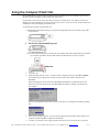
10. From the Start menu, select Programs and tap Save Registry.
Hans Turck GmbH & Co.KG • Witzlebenstraße 7 • 45472 Mülheim/Ruhr • Germany • Tel. +49 (0)208 4952-0 • www.turck.com
4–3
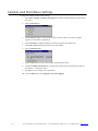
Taskbar and Start Menu Settings
To change the Taskbar and Start Menu settings:
1.
Select Start > Settings> Taskbar & Start Menu. The Taskbar and Start Menu Properties dialog
box opens:
2.
Select the General tab:
3.
Check Always on Top to ensure that the taskbar is always visible, even when a program
appears in a full window (maximized).
4.
Check Auto hide to display the taskbar just when you point to the taskbar area.
5.
Check Show Clock to display the time of day in the taskbar.
6.
Select the Advanced tab:
7.
Tap the Clear button to remove the contents of the documents menu.
8.
Check the Expand Control Panel box to display the contents of the Control Panel as items on
the Settings | Control Panel menu.
9.
Tap OK to save the settings and exit the menu.
10. From the Start menu, select Programs and tap Save Registry.
4–4
Hans Turck GmbH & Co.KG • Witzlebenstraße 7 • 45472 Mülheim/Ruhr • Germany • Tel. +49 (0)208 4952-0 • www.turck.com
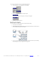
Using the Compact Flash Slot
BL ident-Handheld’s equipped with a standard Compact Flash Slot access cover will allow you to access
the slot to insert and remove Compact Flash and device cards.
If you intend to use a device card, it may also be necessary to install a driver. If so, make sure the card is
Windows CE .net compatible and you have the necessary drivers. If you are not sure, check with the card
manufacturer before attempting to install the card.
To transfer files using the compact flash slot:
1. With the front of the display facing you, push the compact flash slot cover (located on top of the
unit) to the left.
3. Insert the compact flash/device card into the slot with the front of the display facing you and the
top of the card pointed to the slot until it clicks and the release lever moves upward.
4.
Close the cover.
5.
When inserting memory cards, a “UserCF” folder will appear when you open My Computer.
You can then copy and paste the contents of UserCF to the other folders on the BL identHandheld.
When inserting device cards, the BL ident-Handheld will attempt to recognize the device. If it
finds a driver for the device, the BL ident-Handheld will display a dialog box for that device.
For example:
If the BL ident-Handheld cannot find a driver for the device, it will display the following dialog
box:
6.
If the correct card type appears, you can enter the appropriate information in the dialog box as
required and then tap OK to complete the installation.
7.
To remove a card from a slot, simply push the card release lever down and remove the card.
Hans Turck GmbH & Co.KG • Witzlebenstraße 7 • 45472 Mülheim/Ruhr • Germany • Tel. +49 (0)208 4952-0 • www.turck.com
4–5
Network Connections
You can connect directly to a network using one of the following card types to access e-mail, access files
available on the network server, and browse the Internet:
•
Wired Ethernet CF Card
•
WLAN 802.11b (Integrated or CF Card)
•
Bluetooth Class 1 (Integrated or CF Card)
•
Bluetooth Class 2 CF (Integrated or Card)
Creating a Wired Ethernet Network Connection
To create a Wired Ethernet connection:
1.
Insert the Ethernet card into the BL ident-Handheld and connect the cable to the network.
2.
Select Start > Settings > Control Panel. Double-tap Network and Dial-Up Connections.
3.
Double-tap the connection icon for the adapter. For example, if you have a NE2001 Ethernet
adapter, double-click the NE2001 connection icon.
4.
In the Ethernet Driver Settings dialog box, select Obtain an IP address via DHCP and tap OK.
5.
If prompted, enter the User Name, Password, and Domain name you use to log on to your
network.
6.
From the Start menu, select Programs and tap Save Registry.
Creating Network Connection using a WLAN 802.11 b Card
To create a network connection using a WLAN 802.11b card:
4–6
1.
Insert the WLAN 802.11b card into the BL ident-Handheld.
2.
Select Start > Settings > Control Panel. Double-tap Network and Dial-Up Connections.
3.
Double-tap the connection icon for the adapter. For example, if you have a NE2001 Ethernet
adapter, double-click the NE2001 connection icon.
4.
In the Ethernet Driver Settings dialog box, select Obtain an IP address via DHCP and tap OK.
5.
If prompted, enter the User Name, Password, and Domain name you use to log on to your
network.
6.
From the Start menu, select Programs and tap Save Registry.
Hans Turck GmbH & Co.KG • Witzlebenstraße 7 • 45472 Mülheim/Ruhr • Germany • Tel. +49 (0)208 4952-0 • www.turck.com
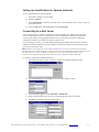
Setting Up Identification for Remote Networks
To set up identification for remote networks:
1.
Select Start > Settings > Control Panel.
2.
Double-tap Owner.
3.
In the Network ID tab, enter the user name, password, and domain name you use to log on to
the remote network.
4.
From the Start menu, select Programs and tap Save Registry.
Connecting to a Mail Server
You can send and receive e-mail by connecting to a POP3 or IMAP4 server. Inbox contains an e-mail
service for each method you use. For either service, you must establish a connection to your Internet
service provider (ISP) or to the appropriate mail server in your local area network. In addition to
creating this connection, you must also create the e-mail service.
Prior to setting up a service, you should obtain the following information from your ISP or network
administrator: POP3 or IMAP4 server name, SMTP host name, user name, password and domain name
(for network connections only).
Notes: Windows CE .Net does not support other mail protocols such as AOL or services that use special
authentication, such as MSN. However, you can gain access to the Internet through these services. If you use
the same service to connect to different mailboxes, set up and name a different service for each
connection. For additional information about the inbox, refer to Windows CE .NET online help.
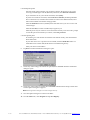
To connect to your POP3 or IMAP4 mail server:
1.
Select Start > Programs > Inbox > Services > Options. The Options dialog box opens.
2.
Select the Services tab and tap Add. The Service Name dialog box opens.
3.
From the Service type list, select POP3 Mail or IMAP4 Mail.
4.
Enter a unique name for the service (you cannot change this name once entered).
5.
Tap OK. The Mail Service Setup wizard appears.
Hans Turck GmbH & Co.KG • Witzlebenstraße 7 • 45472 Mülheim/Ruhr • Germany • Tel. +49 (0)208 4952-0 • www.turck.com
4–7
6. In the Required panel:
Select the name of the connection you created to connect to the mail server. If you are
receiving e-mail through a network (Ethernet) connection, select Network Connection.
If you want Inbox to use your current connection, select (none).
If you have not created a connection, select Create new connection, double-tap the Make
New Connection icon, and follow the instructions in the wizard. When finished, select
Inbox in the Taskbar and continue setting up Inbox.
Enter the POP3 Host or Server (IMAP4) name of the mail server you use to receive and
send messages.
Enter the User ID (user name or mailbox ID) assigned to you.
Enter the password you will use to access this mail account. If you do not want a prompt
to enter the password each time you connect, select Save password.
7. In the Optional panel:
If connecting to a network that uses Windows NT domain security, enter the Windows
NT domain name.
If your mail service uses a separate server for SMTP, enter the SMTP Host name. For
POP3 Mail service with an ISP, the ISP must use an SMTP mail gateway.
Enter your return e-mail address.
8.
Tap Next. The General Preferences dialog box opens.
9.
Choose any of the settings, all of which are optional, then click Next. The Inbox Preferences
dialog box opens.
10. Choose any of the settings as needed, then click Finish. The Mail Service Setup wizard closes
and the Options dialog box reappears.
Note: Receiving entire messages consumes storage memory.
11. Close the Options dialog box to return to the Inbox.
12. From the Start menu, select Programs and tap Save Registry.
4–8
Hans Turck GmbH & Co.KG • Witzlebenstraße 7 • 45472 Mülheim/Ruhr • Germany • Tel. +49 (0)208 4952-0 • www.turck.com
ActiveSyn c
ActiveSync is a desktop utility program (available as a free download from Microsoft) that allows you to
synchronize certain types of information between a PC and the BL ident-Handheld. You can also use
ActiveSync to transfer files and install programs on the BL ident-Handheld.
When connecting the BL ident-Handheld to the PC via ActiveSync, you can opt to create a partnership
and subsequently have the PC automatically recognize the BL ident-Handheld and synchronize
information. You can also create a temporary Guest partnership to copy files and install programs.
The following procedures describe how to make an ActiveSync connection using a serial interface cable. For
information on how to make an ActiveSync connection using Bluetooth or Wi-Fi, refer to the appropriate
manual.
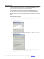
Initial Communication
To setup initial communication between the PC and the BL ident-Handheld:
1.
Connect an interface cable to an available COM port on the PC and the BL ident-Handheld’s
RS-232 port.
2.
On the PC, start ActiveSync.
3.
On the ActiveSync menu bar, select Connection Settings from the File menu. The Connection
Settings dialog box opens.
4.
If not selected, check the Allow serial cable or infrared connection to this COM port box, and
assign the number of the available COM port (typically COM1).
5.
Click OK to exit.
Hans Turck GmbH & Co.KG • Witzlebenstraße 7 • 45472 Mülheim/Ruhr • Germany • Tel. +49 (0)208 4952-0 • www.turck.com
4–9
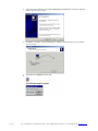
6.
On the ActiveSync menu bar, select Get Connected from the File menu. ActiveSync will then
start the Get Connected wizard.
7.
Click Next. ActiveSync will start attempting to establish a connection (this process will take
several seconds).
On the BL ident-Handheld, tap PC Link
4 – 10
Hans Turck GmbH & Co.KG • Witzlebenstraße 7 • 45472 Mülheim/Ruhr • Germany • Tel. +49 (0)208 4952-0 • www.turck.com
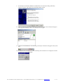
9.
If ActiveSync successfully establishes communications, the ActiveSync dialog will briefly
reappear on the PC and start the New Partnership dialog wizard.
10. Select your Partnership option as needed and complete the wizard. The ActiveSync dialog box
will reappear and display a status of “Connected.” For example:
11. On the BL ident-Handheld, an icon indicating a ActiveSync connection will appear in the system
tray.
12. To terminate the ActiveSync connection, double-tap the connection icon to display the Connect
To dialog box and tap Disconnect.
Hans Turck GmbH & Co.KG • Witzlebenstraße 7 • 45472 Mülheim/Ruhr • Germany • Tel. +49 (0)208 4952-0 • www.turck.com
4 – 11
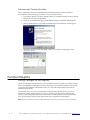
Subsequent Communication
After you install ActiveSync and establish the initial communication between the PC and the BL
ident-Handheld, use the following procedure to set up subsequent sessions:
1.
If not already attached, connect an interface cable to an available COM port on the PC and the
RS-232 port on the BL ident-Handheld.
2.
On the BL ident-Handheld desktop, tap PC Link to attempt to reestablish communications
3.
When communications is successfully reestablished, the New Partnership wizard appears.
4.
Select No on the PC and then click Next. A status of “Connected” should appear in the
ActiveSync window.
Persistent Registry
Saving Changes to the Registry
The BL ident-Handheld internal memory consists of DRAM and Flash. Typically, any changes made to
the BL ident-Handheld including file creation are temporarily stored in the unit’s DRAM. You must then
copy the files from DRAM to internal flash memory or a removable compact flash card to store the
information permanently.
Consequently, if you do not store the information to flash memory and the unit loses power, all
information stored in DRAM will be lost. However, whenever you make changes that affect the
registry, such and changing settings in the Control Panel or installing software, you can permanently
store registry changes without writing to flash memory by using the Persistent Registry.
Note: The BL ident-Handheld will store registry information every time you perform a suspend operation.
4 – 12
Hans Turck GmbH & Co.KG • Witzlebenstraße 7 • 45472 Mülheim/Ruhr • Germany • Tel. +49 (0)208 4952-0 • www.turck.com
To store registry information on the BL ident-Handheldpermanently:
1.
From the Start menu, select Programs and tap SaveReg.
2.
The BL ident-Handheld will begin saving the registry.
After you successfully save the registry, a message box will appear:
3.
Tap OK to close the message box.
Resetting the Registry
To reset the Windows CE .NET registry back to the factory default settings:
1.
Turn off the BL ident-Handheld.
2.
While holding the key in Column 1, Row 1 (upper leftmost) and the key in Column 1, Row 3,
turn on the BL ident-Handheld. For example:
3.
If you are successful, the screen will display version information, followed by “Invalidating
Persistent Registry,” before it completes the boot up process.
Hans Turck GmbH & Co.KG • Witzlebenstraße 7 • 45472 Mülheim/Ruhr • Germany • Tel. +49 (0)208 4952-0 • www.turck.com
4 – 13
4 – 14
Hans Turck GmbH & Co.KG • Witzlebenstraße 7 • 45472 Mülheim/Ruhr • Germany • Tel. +49 (0)208 4952-0 • www.turck.com
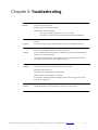
Chapter 5: Troubleshooting
Problem
My BL ident-Handhelddoes not respond when I press the power button.
Solution
Is the unit in Suspend mode?
If battery-powered, check the batteries.
Are all cables connected properly:
•
•
Is the power supply plugged into an active AC outlet?
Is the power connector securely plugged into the BL ident-Handheld
Problem
I changed my system settings, but when I turn on the BL ident-Handheld my settings
are gone.
Solution
You must save the registry after making any system or configuration changes.
Problem
I transferred files to the BL ident-Handheld from my host computer, but when I turn on
the BL ident-Handheld my transferred files are missing.
Solution
To store transferred files permanently, you must file copy the files into internal flash
memory or a compact flash card.
Occasionally, transferred files can be hidden from view, double-tap My Computer,
select Options from the View menu and clear all boxes.
Problem
Solutions
I cannot connect to the development system using ActiveSync.
Did you install ActiveSync using the Administrator account?
Check the cable connections.
Check the serial communications configuration.
Make sure the correct COM port is available.
In ActiveSync, check the Connection Settings for the connection type you are using
(USB, Serial or Ethernet).
Problem
The screen is too light or too dark.
Solution
Adjust the brightness via the brightness control in the Control Panel.
Hans Turck GmbH & Co.KG • Witzlebenstraße 7 • 45472 Mülheim/Ruhr • Germany • Tel. +49 (0)208 4952-0 • www.turck.com
5–1
Problem
The stylus is not responding properly.
Solution
The screen is not calibrated correctly to interpret the screen taps. You need to
recalibrate the screen.
Problem
The BL ident-Handheld acts slowly.
Solutions
The unit may be short of program memory or storage memory.
Increase the amount of storage or program memory through the System control in the
Control Panel. You can also delete any unnecessary files.
Problem
I get little or no sound from the BL ident-Handheld.
Solution
Adjust the volume and sound properties via the Volume and Sound control in the
Control Panel.
Problem
The BL ident-Handheld does not recognize a compact flash or device card.
Solution
The card is not installed or seated properly.
Reinstall the card. There may be an unstable connection between the card and the BL
ident-Handheld.
Remove the card, clean the edge connector with a soft dry cloth, and reinstall the
card.
Problem
The BL ident-Handheld goes into auto-suspend after a short period of inactivity.
Solution
As a default, the device will auto-suspend after two minutes of inactivity while
running on batteries and after thirty minutes of inactivity when running on AC
power.
Adjust the power management properties via the Power control in the Control
Panel.
Problem
No sound is heard when you tap the touch screen or press a key.
Solution
Volume setting is low or turned off.
Check the volume slider in the Volume & Sound properties dialog box in the
Control Panel.
5–2
Hans Turck GmbH & Co.KG • Witzlebenstraße 7 • 45472 Mülheim/Ruhr • Germany • Tel. +49 (0)208 4952-0 • www.turck.com
Appendix A: Specifications
Power
Recharge Voltage: 11 to 18 VDC, 1.5A (North America Only)
Battery Type: Nickel Metal Hydride Rechargeable (or 6 AA alkaline batteries)
~
~
~
Current Rating: 2 Amp Maximum
Voltage: 7.2 Volts
Capacity: 1400 mAh
Display
Supertwist Nematic Liquid Crystal TFT with white LED backlight
Resolution: 320 x 240 pixels QVGA color
Touch Screen
Environmental
Operating Temperature: 0°C to +50°C
Storage Temperature: -25°C to +70°C
Charging Temperature: 0°C to + 40°C
Humidity: 5-95% Non-condensing
CPU
Type: Intel PXA255 processor with XScale technology
Instruction Set Architecture: ARM v.5TE
Speed: 200 MHz (400 MHz optional)
Operating System: Windows CE .NET 4.2 Prof essional
Memory and Mass Storage
SDRAM: 64MB
Internal Compact Flash: 64 MB standard (16MB reserved for OS), upgradeable to 128MB
Optional: Compact flash card slot
RFID Module
Multi-protocol read/write support for 13.56MHz RFID tag types including ISO-15693, Tag-It by
Texas Instruments, I Code by Philips, GemWave by TagSys, and PicoTag from Inside Contactless
(see Table 1-1 for specifics).
Read Range: 3.152-3.546 inches (80-90 mm)
Output Power Measurement: 22.8 dbm = 200 mW
User Input
Touch Screen
Key Pad: 45-Key membrane (9 rows x 5 columns) or 15-key elastomeric (5 x 3)
Feedback: Tactile and audible
Optional: LED backlighting
Hans Turck GmbH & Co.KG • Witzlebenstraße 7 • 45472 Mülheim/Ruhr • Germany • Tel. +49 (0)208 4952-0 • www.turck.com
A–1
Indicators
5 Modifier Key/Programmable LEDs
Charge/Low Battery Indicator (battery-powered units only)
Interface Capability
One available serial port configured for RS-232 that can also provide input power (11–18VDC)
and recharging capability.
Optional interface connectors (available at time of factory configuration) include the BL
ident connect system, DE-9 male or female connectors and a six-pin modular connector.
Interface connections (available at time of factory configuration) can optionally provide output at 5
VDC to operate peripheral devices.
Physical Dimensions
Height (H): 9.84 Inches (250 mm)
Width (W): 4.75 Inches (120.7 mm)
Depth (D): 2.37 Inches (60.2 mm)
Weight :
•
Without Batteries: 27 Ounces (765.4 grams)
•
With Alkaline Batteries: 32 Ounces (907.2 grams)
•
With NiMH Batteries: 33 Ounces (935.5 grams)
2.82
S p e c i f i c a ti on s s u b j e c t to c h a n g e
A–2
Hans Turck GmbH & Co.KG • Witzlebenstraße 7 • 45472 Mülheim/Ruhr • Germany • Tel. +49 (0)208 4952-0 • www.turck.com
Appendix B: Signal and Pin Assignments
BL ident Connect Cables
Figures B-1 and B-2 list the standard RS-232 signal and pin assignments for the BL ident connect cables. Figure 6-2: 91708
Cable (Male DE9) RS-232 Signal and Pin Assignments
11 9 7 5 3 1
1 2 3 4 5
Viewed Facing
Connector
6 7 8 9
12 10 8 6 4 2
BLident
Connect
JETT• Connect
DE 9 Connector
White w/Black Stripe
Pin 1 (Reserved)
Pin 2 (GND)
Pin 3 (RI)
Pin 4 (CTS)
Pin 5 (DTR)
Pin 6 (TXD)
Pin 7 (DSR)
Pin 8 (RTS)
Pin 9 (DCD)
Pin 10 (PWR)
Power
Blue
Gray
Black
Violet
Yellow
Brown
Red
Orange
Pin 5 (GND)
Pin 9 (RI)
Pin 8 (CTS)
Pin 4 (DTR)
Pin 3 (TXD)
Pin 6 (DSR)
Pin 7 (RTS)
Pin 1 (DCD)
White
Pin 11 (SHIELD)
Pin 12 (RXD)
Green
Pin 2 (RXD)
Hans Turck GmbH & Co.KG • Witzlebenstraße 7 • 45472 Mülheim/Ruhr • Germany • Tel. +49 (0)208 4952-0 • www.turck.com
B–1
Figure 6-3: 91709 Cable (Female DE9) RS-232 Signal and Pin Assignments
Viewed Facing
Connector
BLident Connect
JETT• Connect
DE 9 Connector
Pin 1 (Reserved)
Pin 2 (GND)
Pin 5 (GND)
Gray
Pin 3 (RI)
Red
Pin 4 (CTS)
Pin 5 (DTR)
Power
White w\Black Stripe
Orange
Green
Pin 9 (RI In)
Pin 7 (CTS In)
Pin 1 (DTR Out)
Pin 6 (TXD)
Pin 2 (TXD Out)
Pin 7 (DSR)
Pin 6 (DTR Out)
Pin 8 (RTS)
Pin 8 (RTS Out)
Pin 9 (DCD)
Pin 4 (DSR/DCD In)
Pin 10 (PWR)
Pin 11 (SHIELD)
Pin 12 (RXD)
Yellow
Pin 3 (RXD In)
1210 Series Modular Interface Cables
Figure B-3 lists the signal and pin assignments for 1210 series modular cables.
Figure 6-4: 1210 Series Modular Cable Signal and Pin Assignments
Pin 1
Pin 6
6-Pin Modular Jack
B–2
Pin 6
Pin 1
6-Pin Modular Jack
Pin 1 (Blue)
Pin 6
Pin 2 (Yellow)
Pin 5
Pin 3 (Green)
Pin 4
Pin 4 (Red)
Pin 3
Pin 5 (Black)
Pin 2
Pin 6 (White)
Pin 1
Hans Turck GmbH & Co.KG • Witzlebenstraße 7 • 45472 Mülheim/Ruhr • Germany • Tel. +49 (0)208 4952-0 • www.turck.com
Modular Cable Adapters
Pin descriptions assume connection through reversing cables (1210-7, 1210-15) to BL identHandheld.
CELAT-P Adapter
Figure B-4 lists the signal and pin assignments for the CELAT-P adapter.
Figure 6-5: CELAT-P Adapter
Pin 5
Pin 6
Pin 1
Pin 9
Viewed Facing
Connector
6-Pin Modular Jack
Pin 1 (Blue)
Pin 2 (Yellow)
Pin 3 (Green)
Pin 4 (Red)
Pin 5 (Black)
Pin 6 (White)
Pin 1
Pin 6
DE 9 Connector
Power
Pin 5 (Common)
Pin 2 (Data Out)
Pin 3 (Data In)
Pin 1 (CTS)
Pin 6 (RTS)
Pin 8 (Handshake Out)
Pin 7 (Handshake Out)
Pin 4
Pin 9 (RI)
Null Modem Cable
Figure B-5 lists the signal and pin assignments for TURCK’ 14375 DE-9 Female to DE-9 Female null
modem cable. Please note that this cable differs from standard null modem cables in that it use Pin 9 for
input power for the BL ident-Handheld.
Figure 6-6: DE-9 Female to DE-9 Female Null Modem Cable
1 2 3 4 5
1 2 3 4 5
Viewed Facing
Connector
6 7 8 9
Female DE9 Connector
6 7 8 9
Female DE9 Connector
Pin 1 (Blue)
Pin 1
Pin 2 (Green)
Pin 3 (Yellow)
Pin 2
Pin 3
Pin 4 (Orange)
Pin 5 (Gray)
Pin 4
Pin 5
Pin 6 (Blue)
Pin 6
Pin 7 (Red)
Pin 7
Pin 8 (Violet)
Pin 8
Pin 9 (Brown)
Pin 9
Power Jack
Hans Turck GmbH & Co.KG • Witzlebenstraße 7 • 45472 Mülheim/Ruhr • Germany • Tel. +49 (0)208 4952-0 • www.turck.com
B–3
Appendix C: Keyboard Mapping Files
Keyboard Mapping Files Notes
The following table lists the allowable values and the names of allowable values that you can map to a
keypad.
Table 6-1: Allowed Values in Key Map Files
A
V
CARET
F9
NUMPAD1
SEMICOLON
B
W
CLEAR
F10
NUMPAD2
SHIFT
C
X
COLON
F11
NUMPAD3
SLASH
D
Y
COMMA
F12
NUMPAD4
SPACE
E
Z
CONTROL
FUNCTION
NUMPAD5
STAR
F
(
DELETE
HASH
NUMPAD6
SUBTRACT
G
)
DOLLAR
HOME
NUMPAD7
TAB
H
[
DOUBLEQUOTE
INSERT
NUMPAD8
TILDA
I
]
DOWN
LEFT
NUMPAD9
UNDERLINE
J
{
END
KEY0
PAGEDOWN
UP
K
}
EQUAL
KEY1
PAGEUP
USER_DEF1
L
<
ESCAPE
KEY2
PAUSE
USER_DEF2
M
>
EXCLAMATION
KEY3
PERCENT
USER_DEF3
N
ADD
F1
KEY4
PERIOD
USER_DEF4
O
ALT
F2
KEY5
PIPE
USER_DEF5
P
AMPERSAND
F3
KEY6
PRINT
USER_DEF6
Q
AT
F4
KEY7
QUESTION
USER_DEF7
R
BACKQUOTE
F5
KEY8
QUOTE
USER_DEF8
S
BACKSLASH
F6
KEY9
RETURN
USER_DEF9
T
BACKSPACE
F7
NUMLOCK
RIGHT
USER_DEF10
U
CAPSLOCK
F8
NUMPAD0
SCROLL
WINMENU
Scan codes “USER_DEF1” through “USER_DEF10” can produce some proprietary action, such as
backlight adjustment, display rotation, etc. For each user-defined key-function (except as noted below), you
must supply the appropriate code in the keyboard driver to produce the desired effect. "USER_DEF3"
defines the Backlight+ key and "USER_DEF4" defines the Backlight– key.
The "FUNCTION" keyword identifies those function accessed through the "2nd" key. The “RETURN"
keyword identifies the "ENTER" key. The "WINMENU" keyword produces the Windows "Start" menu.
The number in COLS must always be set to five regardless of the actual number of columns (applies to
15-key keypads as well).
Do not change the ID number, it must match the number stored in the BL ident-Handheld’s
hardware configuration block.
Hans Turck GmbH & Co.KG • Witzlebenstraße 7 • 45472 Mülheim/Ruhr • Germany • Tel. +49 (0)208 4952-0 • www.turck.com
C–1
45-Key Key Map
# 55 Key JettCE keyboard for P/N 11406 Rev A. keypad
# The keyword "FUNCTION" is used for the "2nd" key.
# The keyword "RETURN" is used for the "ENTER" key.
# "USER_DEF1" defines the Contrast+ key
# "USER_DEF2" defines the Contrast- key
# "USER_DEF3" defines the Backlight-INCREASE key
# "USER_DEF4" defines the Backlight-DECREASE key
# "WINMENU" produces the Windows "Start" menu.
# The line and the end of the line
ROWS 11
COLS 5
# The id of the keyboard.
ID 55
# The basic scan codes.
#
Row,Col,Scan Code
SCANCODE 0, 0-> A
SCANCODE 0, 3-> D
SCANCODE 1, 2-> G
SCANCODE 2, 1-> J
SCANCODE 3, 0-> M
SCANCODE 3, 3-> P
SCANCODE 4, 2-> S
SCANCODE 5, 1-> V
SCANCODE 6, 0-> Y
SCANCODE 6, 3-> KEY9
SCANCODE 7, 2-> KEY5
SCANCODE 8, 1-> KEY1
SCANCODE 9, 0-> BACKSPACE
SCANCODE 9, 3-> RETURN
FUNCTION
SCANCODE 10, 2 -> CONTROL
SCANCODE
SCANCODE
SCANCODE
SCANCODE
SCANCODE
SCANCODE
SCANCODE
SCANCODE
SCANCODE
SCANCODE
SCANCODE
SCANCODE
SCANCODE
SCANCODE
0, 1 -> B
1, 0 -> E
1, 3 -> H
2, 2 -> K
3, 1 -> N
4, 0 -> Q
4, 3 -> T
5, 2 -> W
6, 1 -> KEY7
7, 0 -> Z
7, 3 -> KEY6
8, 2 -> KEY2
9, 1 -> SPACE
10, 0 -> SHIFT
SCANCODE 10, 3 -> ALT
SCANCODE 0, 2 -> C
SCANCODE 1, 1 -> F
SCANCODE 2, 0 -> I
SCANCODE 2, 3 -> L
SCANCODE 3, 2 -> O
SCANCODE 4, 1 -> R
SCANCODE 5, 0 -> U
SCANCODE 5, 3 -> X
SCANCODE 6, 2 -> KEY8
SCANCODE 7, 1 -> KEY4
SCANCODE 8, 0 -> PERIOD
SCANCODE 8, 3 -> KEY3
SCANCODE 9, 2 -> KEY0
SCANCODE 10, 1 ->
SCANCODE 10, 4 -> ESCAPE
# Table 0 is always the unshifted values.
TABLE 0, basic, UNSHIFTED
TABLE 1, func, FUNCTION
TABLE 2, shift, SHIFT
# Func remapping table.
REMAPPING func, A -> DELETE
REMAPPING func, C -> PAGEDOWN
REMAPPING func, E -> CAPSLOCK
REMAPPING func, G -> CLEAR
REMAPPING func, I -> {
REMAPPING func, K -> PAUSE
REMAPPING func, M -> BACKTAB
REMAPPING func, O -> COLON
REMAPPING func, Q -> USER_DEF2
REMAPPING func, S -> HASH
REMAPPING func, U -> USER_DEF4
REMAPPING func, W -> WINMENU
REMAPPING func, Y -> F11
REMAPPING func, PERIOD -> BACKSLASH
REMAPPING func, KEY8 -> F8 REMAPPING
func, KEY4 -> F4 REMAPPING func, KEY6 > F6
C–2
REMAPPING func, B -> PAGEUP
REMAPPING func, D -> INSERT
REMAPPING func, F -> HOME
REMAPPING func, H -> SCROLL
REMAPPING func, J -> TILDA
REMAPPING func, L -> }
REMAPPING func, N -> CARET
REMAPPING func, P -> TAB
REMAPPING func, R -> PIPE
REMAPPING func, T -> USER_DEF1
REMAPPING func, V -> COMMA
REMAPPING func, X -> USER_DEF3
REMAPPING func, Z -> F12
REMAPPING func, KEY7 -> F7
REMAPPING func, KEY9 -> F9
REMAPPING func, KEY5 -> F5
REMAPPING func, KEY1 -> F1
Hans Turck GmbH & Co.KG • Witzlebenstraße 7 • 45472 Mülheim/Ruhr • Germany • Tel. +49 (0)208 4952-0 • www.turck.com
REMAPPING func, KEY3 -> F3
REMAPPING func, KEY2 -> F2
REMAPPING func, KEY0 -> F10
# Shift remapping table.
REMAPPING shift, A -> LEFT
REMAPPING shift, C -> DOWN
REMAPPING shift, E -> <
REMAPPING shift, G -> UNDERLINE
REMAPPING shift, I -> (
REMAPPING shift, K -> SEMICOLON
REMAPPING shift, M -> [
REMAPPING shift, O -> BACKQUOTE
REMAPPING shift, Q -> AMPERSAND
REMAPPING shift, S -> QUOTE
REMAPPING shift, U -> SUBTRACT
REMAPPING shift, W -> EQUAL
REMAPPING shift, Y -> PERCENT
REMAPPING shift, PERIOD -> DOUBLEQUOTE
#REMAPPING shift, KEY8 ->
#REMAPPING shift, KEY4 ->
#REMAPPING shift, KEY6 ->
#REMAPPING shift, KEY2 ->
#REMAPPING shift, KEY0 ->
REMAPPING shift, B -> UP
REMAPPING shift, D -> RIGHT
REMAPPING shift, F -> END
REMAPPING shift, H -> >
REMAPPING shift, J -> EXCLAMATION
REMAPPING shift, L -> )
REMAPPING shift, N -> QUESTION
REMAPPING shift, P -> ]
REMAPPING shift, R -> AT
REMAPPING shift, T -> DOLLAR
REMAPPING shift, V -> SLASH
REMAPPING shift, X -> ADD
REMAPPING shift, Z -> STAR
#REMAPPING shift, KEY7 ->
#REMAPPING shift, KEY9 ->
#REMAPPING shift, KEY5 ->
#REMAPPING shift, KEY1 ->
#REMAPPING shift, KEY3 ->
30-Key Key Map
# 31 Key JettCE keyboard definition file
# The keyword "FUNCTION" is used for the "2nd" key.
# The keyword "RETURN" is used for the "ENTER" key.
# "USER_DEF1" defines the Contrast+ key
# "USER_DEF2" defines the Contrast- key
# "USER_DEF3" defines the Backlight-INCREASE key
# "USER_DEF4" defines the Backlight-DECREASE key
# "WINMENU" produces the Windows "Start" menu.
# The line and the end of the line
ROWS 10
COLS 5
# The id of the keyboard.
ID 31
# Table 0 is always the unshifted values.
TABLE 0, basic, UNSHIFTED
TABLE 1, shift, SHIFT
# The basic scan codes.
#
Row,Col,Scan Code
SCANCODE 0, 0 -> A
SCANCODE 1, 0 -> D
SCANCODE 2, 0 -> G
SCANCODE 3, 0 -> J
SCANCODE 4, 0 -> M
SCANCODE 5, 0 -> P
SCANCODE 6, 0 -> S
SCANCODE 7, 0 -> V
SCANCODE 8, 0 -> Y
SCANCODE 9, 0 -> SHIFT
SCANCODE
SCANCODE
SCANCODE
SCANCODE
SCANCODE
SCANCODE
SCANCODE
SCANCODE
SCANCODE
SCANCODE
0,
1,
2,
3,
4,
5,
6,
7,
8,
9,
1
1
1
1
1
1
1
1
1
1
-> B
-> E
-> H
-> K
-> N
-> Q
-> T
-> W
-> Z
-> SPACE
SCANCODE 0,2
SCANCODE 1,2
SCANCODE 2,2
SCANCODE 3,2
SCANCODE 4,2
SCANCODE 5,2
SCANCODE 6,2
SCANCODE 7,2
SCANCODE 8,2
SCANCODE 9,2
Hans Turck GmbH & Co.KG • Witzlebenstraße 7 • 45472 Mülheim/Ruhr • Germany • Tel. +49 (0)208 4952-0 • www.turck.com
-> C
-> F
-> I
-> L
-> O
-> R
-> U
-> X
-> ESCAPE
-> RETURN
C–3
# Shift remapping table.
REMAPPING shift, A -> LEFT
REMAPPING shift, C -> RIGHT
REMAPPING shift, E -> UP
REMAPPING shift, G -> TAB
REMAPPING shift, I -> COMMA
REMAPPING shift, K -> COLON
REMAPPING shift, M -> USER_DEF4
REMAPPING shift, O -> USER_DEF3
REMAPPING shift, Q -> KEY8
REMAPPING shift, S -> KEY4
REMAPPING shift, U -> KEY6
REMAPPING shift, W -> KEY2
REMAPPING shift, Y -> ALT
REMAPPING shift, ESCAPE -> PERIOD
REMAPPING shift, B -> DOWN
REMAPPING shift, D -> SUBTRACT
REMAPPING shift, F -> ADD
REMAPPING shift, H -> QUESTION
REMAPPING shift, J -> BACKSLASH
REMAPPING shift, L -> SLASH
REMAPPING shift, N -> STAR
REMAPPING shift, P -> KEY7
REMAPPING shift, R -> KEY9
REMAPPING shift, T -> KEY5
REMAPPING shift, V -> KEY1
REMAPPING shift, X -> KEY3
REMAPPING shift, Z -> KEY0
REMAPPING shift, SPACE -> BACKSPACE
15-Key Key Map
# Copyright (c) 2003 TURCK Corporation. All rights reserved.
# File: JET15Key.txt
#
# 15 Key JETT.ce keyboard, REV 1
# The keyword "FUNCTION" is used for the "2nd" key.
# The keyword "RETURN" is used for the "ENTER" key.
# "USER_DEF1" defines the Contrast+ key
# "USER_DEF2" defines the Contrast- key
# "USER_DEF3" defines the Backlight-On key
# "USER_DEF4" defines the Backlight-Off key
# "WINMENU" produces the Windows "Start" menu.
# The number of rows and columns.
# Note: COLS MUST ALWAYS be a 5
ROWS 5
COLS 5
# The id of the keyboard.
ID 15
# The basic scan codes.
#
Row,Col,Scan Code
SCANCODE 0, 0 -> TAB
SCANCODE 1, 0 -> LEFT
SCANCODE 2, 0 -> SUBTRACT
SCANCODE 3, 0 -> ESCAPE
SCANCODE 4, 0 -> FUNCTION
SCANCODE 0,
SCANCODE 1,
SCANCODE 2,
SCANCODE 3,
SCANCODE 4,
1->
1->
1->
1->
1->
UP
BACKSLASH
DOWN
PERIOD
CONTRO
SCANCODE 0,2
SCANCODE 1,2
SCANCODE 2,2
SCANCODE 3,2
SCANCODE 4,2
-> ALT
-> RIGHT
-> ADD
-> RETURN
-> SPACE
# Table 0 is always the unshifted values.
TABLE 0, basic, UNSHIFTED
TABLE 1, func, FUNCTION
TABLE 2, shift, SHIFT
# func remapping table.
REMAPPING func, TAB
REMAPPING func, ALT
REMAPPING func, BACKSLASH
REMAPPING func, SUBTRACT
REMAPPING func, ADD
REMAPPING func, PERIOD
USER_DEF3
C–4
-> KEY1
-> KEY3
-> KEY5
-> KEY7
-> KEY9
-> KEY0
REMAPPING func,
REMAPPING func,
REMAPPING func,
REMAPPING func,
REMAPPING func,
REMAPPING func,
UP
LEFT
RIGHT
DOWN
ESCAPE
RETURN
-> KEY2
-> KEY4
-> KEY6
-> KEY8
-> USER_DEF4
->
Hans Turck GmbH & Co.KG • Witzlebenstraße 7 • 45472 Mülheim/Ruhr • Germany • Tel. +49 (0)208 4952-0 • www.turck.com
#REMAPPING func, FUNCTION
CONTROL
-> WINMENU
REMAPPING func, SPACE
-> BACKSPACE
-> REMAPPING func,
Hans Turck GmbH & Co.KG • Witzlebenstraße 7 • 45472 Mülheim/Ruhr • Germany • Tel. +49 (0)208 4952-0 • www.turck.com
C–5
Index
1
C
1210 Series Modular Cable ......................................2-5, B-2
15-Key Key Map................................................................C-4
15-Key Keypad.................................................................. 3-6
Cable Connections.............................................................2-5
Case Dimensions .............................................................A-2
CE Keyboard ......................................................................3-7
CeKeys ................................................................................3-7
CELAT-P Adapter ..................................................... 2-5, B-3
Certificates..........................................................................4-1
Changing System Settings................................................4-3
Charge\Low Battery Indicator ........................................3-2
Charge\Low Battery Indicator Functions......................3-2
Charging the Unit..............................................................3-1
CHG Indicator ..................................................................3-2
Compact Flash Slot Cover ................................................2-3
Connecting to a Mail Server.............................................4-7
Control Panel .....................................................................4-1
Control Panel Functions ..................................................4-1
CPU Specifications ..........................................................A-1
CPU Speed..........................................................................4-1
Creating a Wired Ethernet Network Connection..........4-6
CTRL Key ...........................................................................3-7
2
2ND Key ............................................................................ 3-7
2ND Mode ........................................................................ 3-7
3
30-Key Key Map................................................................C-3
30-Key Keypad.................................................................. 3-6
4
45-Key Key Map................................................................C-2
45-Key Keypads ............................................................... 3-6
A
About RFID........................................................................ 1-1
About the BL ident-Handheld ......................................... 1-2
About this Manual............................................................ 1-1
ActiveSync ......................................................................... 5-1
Allowed Values in Key Map Files .................................C-1
ALT Key ............................................................................. 3-7
Aux Switch ........................................................................ 4-1
B
Backlight ............................................................................ 4-1
Battery Compartment....................................................... 2-2
Battery Indicator .............................................................. 2-1
Battery Select ..................................................................... 4-1
Beep Select ........................................................................ 4-1
Bluetooth Device Properties ............................................ 4-1
D
Data Entry .........................................................................3-8
Date/Time..........................................................................4-1
Desktop Functions.............................................................3-9
Development Tools ..........................................................5-1
Dialing ...............................................................................4-1
Display.........................................................................2-1, 4-1
Display Rotation................................................................4-1
Display Specifications......................................................A-1
Displays ..............................................................................1-3
Durability ...........................................................................1-3
E
Environmental Specifications ........................................A-1
Hans Turck GmbH & Co.KG • Witzlebenstraße 7 • 45472 Mülheim/Ruhr • Germany • Tel. +49 (0)208 4952-0 • www.turck.com
I–1
F
Front Components and Indicators ................................. 2-1
Fully/Near Full Charge .................................................. 3-2
H
High Power Charge ......................................................... 3-2
Hot Keys ........................................................................... 4-1
I
Inbox .................................................................................. 3-9
Indicator Specifications .................................................. A-2
Indicators ......................................................................... 1-3
Input Panel ....................................................................... 4-2
Interface Capabilities ....................................................... 1-3
Interface Specifications................................................... A-2
Internet Explorer .............................................................. 3-9
Internet Options ............................................................... 4-2
K
Key Repeat ....................................................................... 3-7
Keyboard........................................................................... 4-2
Keyboard Mapping........................................................ 5-34
Keyboard Mapping Files.................................................C-1
Keyboard Mapping Files Notes .....................................C-1
Keypad .............................................................................. 2-1
Keypads...................................................................... 1-3, 3-6
L
LEDs ......................................................................... 2-1, 5-13
LOW BAT Indicator......................................................... 3-2
M
Memory and Mass Storage ............................................ 1-2
Memory and Mass Storage Specifications ................... A-1
Modifier Keys .................................................................. 3-6
Modular Cable Adapters ................................................ B-3
Modular to DE-9S Adapter............................................. 2-5
Modular-to-Modular Cable ............................................ 2-5
My Computer ................................................................... 3-9
My Documents ................................................................ 3-9
N
Network and Dial-up Connections................................ 4-2
Network Connections...................................................... 4-6
Null Modem Cable .......................................................... B-3
I–2
Hans Turck GmbH & Co.KG • Witzlebenstraße 7 • 45472 Mülheim/Ruhr • Germany • Tel. +49 (0)208 4952-0 • www.turck.com
O
On/Off Switch.................................................................. 2-1
Operating System............................................................. 1-2
Operation .......................................................................... 3-1
Overview........................................................................... 1-1
Owner................................................................................ 4-2
P
Partnership ....................................................................... 4-9
Password........................................................................... 4-2
PC Connection.................................................................. 4-2
Persistent Registry ......................................................... 4-12
Physical Dimensions....................................................... A-2
Power.......................................................................... 3-1, 4-2
Power Management......................................................... 3-4
Power Off .......................................................................... 3-4
Power On .......................................................................... 3-3
Power Requirements ..................................................... A-1
Power Status Icons......................................................... 3-10
Power Supply ...........................................................2-5, A-1
Power/Suspend Switch .................................................. 3-3
Processor ........................................................................... 1-2
R
Rechargeable Battery Pack.............................................. 1-2
Recycle Bin ....................................................................... 3-9
Regional Settings ............................................................. 4-2
Remove Programs ........................................................... 4-2
Resetting the Registry ................................................... 4-13
RFID Module ................................................................... 2-2
RFID Read Range ............................................................ 3-8
Specifications ...................................................................A-1
Start Menu .......................................................................3-10
Storage Manager...............................................................4-2
Stylus..................................................................................4-2
Suspend Function Control ............................................5-13
Suspend Mode .................................................................3-4
System ................................................................................4-2
SystemCF Folder.............................................................3-10
T
Taskbar ..............................................................................3-9
Taskbar and Start Menu Settings....................................4-4
The Windows CE .NET Desktop ....................................3-9
Trickle Charge...................................................................3-2
Troubleshooting................................................................6-1
U
User Input Specifications................................................A-1
Using ActiveSync .............................................................4-9
Initial Communication .................................................4-9
Subsequent Communication .....................................4-12
Using the Compact Flash Slot .........................................4-5
Using the RFID Module................................................3-8
V
VComAdj ...........................................................................4-2
S
Saving Changes to the Registry ................................... 4-12
Setting Up Identification for Remote Networks ......... 4-7
SHIFT Key ........................................................................ 3-7
Shift Mode ........................................................................ 3-7
Signal and Pin Assignments ..........................................B-1
Hans Turck GmbH & Co.KG • Witzlebenstraße 7 • 45472 Mülheim/Ruhr • Germany • Tel. +49 (0)208 4952-0 • www.turck.com
I–3
Hans Turck GmbH & Co. KG
45472 Mülheim an der Ruhr,
Germany
Witzlebenstraße 7
Tel. +49 (0) 208 4952-0
Fax +49 (0) 208 4952-264
E-Mail [email protected]
Internet www.turck.com
D101585 0406
*D101585ßß0406*
www.turck.com