1
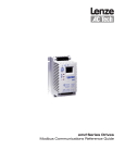
BPS COF.L.BEC1
CDE BIPOL IEEE
User Manual
B-EC1
BRUKER
Page 1
Description of B-EC1
Local and remote control of the power supply
Page
3
3
4
4
1.
1.1
1.1.1
1.1.2
Local control via front panel
Theory of operation
Analog knob
Status information’s
1.2
1.2.1
1.2.2
1.2.2.1
1.2.3
1.2.4
1.2.5
1.2.6
1.2.7
1.2.8
1.2.9
1.2.10
1.3
Explanation of available functions
Change of local/remote state
Reset of power supply
Command flow abort
DC-power on/off
Set polarity positive/negative
Set current
Internal reference, DAC
External reference, 0 .. 10 Volt
External regulation, BH-15 field stabilization (option)
Display selection
ADC read back
Cycle function
7
7
8
9
11
13
15
15
17
19
21
24
25
2.
2.1
2.1.1
2.2
Remote control
via RS 232 C
via IEEE488, selecting address and end sign
Commands and arguments
Power supply state
Example of operation
30
30
30
32
35
39
3.
Installation of BH-15 control, setup
40
4.
Hardware information
41
Bruker Biospin
Page 2
1
B-EC 1
2
3
4
DC
5
SET
6
CUR
7
8
ON
LOCAL
REMOTE
1:
2:
3:
4:
5:
6:
7:
8:
Display DAC current, ADC read back, DC on/off and error messages
Key DC ON/OFF, RESET, POLARITY with LED, needs SET for complement
Key Display selection, ADC read back
Key SET, complement for every LED blinking command
Key CUR, EXTERNAL REFERENCE, BH-15 REGULATION and CYCLE with
LED, needs SET
Analog knob
Remote / local key
Electronic ON key
Explanation of technical terms, not all topics applicable for all power supplies:
ADC:
DAC:
LED:
AC:
DC:
DCCT:
APB:
Analog knob:
RS 232 C:
o
C:
Uce:
Bruker Biospin
Analog Digital Converter, converts analog voltage to a digital code
Digital-Analog-Converter, converts digital code to an analog voltage
Light Emitting Diode
Alternate Current
Direct Current
DC Current Transformer, zero flux current transformer
Analog Processing Box, contains DCCT and regulation prints
Digital encoder, can be used like an potentiometer
Serial interface norm
Degree Celsius
Collector/emitter voltage of power stage
Page 3
1.
Local control via front panel
1.1
Theory of operation
The following chapters describe the local operation of the power supply controller B-EC1.
Throughout the text, the commands and messages concerning the serial interface are
described parallel to their manual operation.
B-EC 1
Internal Ref
DC
SET
CUR
ON
LOCAL
REMOTE
Upon electronic power on, the controller is in an initialization state, DC is off, the
reference is set internal and the nominal current is set to zero. Reacting on any key
press, the status of the power supply is displayed on the front panel. Commands are
initiated by pushing one of the command keys. When a command needs an argument,
this will be indicated on the key by a blinking LED. The 'SET'-key completes every
blinking LED command.
Commands can be skipped by pushing an alternate command key. Keys with more than
one function, like 'DC', 'CUR' and the 'Display selection key', can be pushed multiple
times, the according menus are arranged in a closed loop. Illegal keystrokes are flagged
and ignored. Possible error messages are:
Remote info Local message
E01
E02
E03
E04
E05
E06
E07
E08
E09
Bruker Biospin
FUNCTION E.
Explanation
Function not supported, e.g. during polarity
reversal
ARGUMENT E. The argument contains unknown characters not likely in local operation
PORT N/AVAIL Port not available - this error is not likely in a
single port system
LOCAL ERROR Access denied, check the local / remote switch
RANGE ERROR The argument is out of the allowed range - not
likely in local operation
REF. ERROR
Access denied, Ext Ref or BH-15 active
E. PENDING
DC command denied, there is still an error
pending
CYCLE ERROR Access denied, cycle is active
DC ERROR
Access denied, DC power is OFF
Page 4
1.1.1
Analog knob
The command 'CUR' allow the use of the quasi analog control knob. Turning the knob
slowly, the output can be changed by single bits, increasing the speed will change at a
more than proportional rate.
This quasi-analog setting is stored in the internal memory of nominal values and can be
preset and read back using the appropriate command key or remote command. Pushing
the 'SET'-key disables the knob for the function.
B-EC 1
Internal Ref
DC
SET
CUR
ON
LOCAL
REMOTE
1.1.2
Status information
The power supply is equipped with a security system, its status is read out at the text
display. Every error leading to a power-off state of the supply is displayed, multiple errors
are flagged in a short form as given in the following table.
By some power supplies, not all interlocks are supported, and might not appear.
In detail
Short form
Explanation
WATER ERROR
W
P
T
D
1
I
C
U
Water missing
Line Phase missing
Temperature error
Door opened
External error 1
Inrush fail
Current limit
Polarity Unit
PHASE ERROR
TEMP ERROR
DOOR ERROR
EXTERN E. 1
INRUSH E.
CUR LIMIT
POLARITY E.
The error messages give information’s about the status of the power supply. Actions
necessary upon any error shall now be described more in detail. Also, here is described,
what can be done first to recover from an error. But please keep always in mind: The
power supply is operated with line voltages, which may be hazardous. Therefore, please
be sure what you are doing, before you open any cover or housing.
Bruker Biospin
Page 5
Message 'Water Error', short form 'W', remote '0001Hex': Check your local water
system, all valves should be opened, water pressure must be corresponding to the PS
documentation, also the outlet should not reduce the difference pressure between input
to output to less than the value seen in the documentation.
If the power supply still displays the water error, please check the water flow switch.
Message 'Phase Error', short form 'P', remote '0002Hex': One of the line phases might
be missing. Please check them with a volt meter, but please keep in mind the personal
hazard of line voltages. Also, the mains transformer may have a loose connection, they
can be re-fastened after power down of the system.
Some power supplies have phase follow dependent detectors, so it can be useful to
exchange two phases.
Message 'Temp Error', short form 'T', remote '0004Hex': This message is derived from
several temperature contacts in the power supply. First, please try to check the
impedance of the external load. Perhaps it became low, e.g. due to a short circuit. This
measurement can be made with the power supply itself after cooling down the faulty
channel to a sufficient level (check the ADC I and U read back).
Another possibility can be a bad cooling water condition, e.g. high input temperature or
high output pressure. If these tests should not bring a positive result, please check the
fuses of the pass bank. If more than two transistors should have blown their fuses,
please change them individually, or change the complete pass bank, what ever may be
easier.
Message 'Door Error', short form 'D', remote '0010Hex': The door on the backside of the
power supply is opened. The power supply is switched off for security reasons. It seems
to be a straightforward solution of this error to short-circuit the contact, but please keep in
mind the personal security of you and your staff.
Option: Message 'Ground Error', short form 'G', remote '0020Hex': The ground contact
relay has tripped due to a ground voltage exceeding about 10 volt. This results from a
ground leak in the power supply or of the load magnet, which can be disconnected to
locate the problem.
Message 'Extern E. 1', or 'EXTERN E. 2, respectively short form '1' or '2', remote
'0008Hex' or '0040Hex': This is a message derived from the external interlock contacts.
Bruker Biospin
Page 6
Message 'Cur Limit', short form 'C', remote '0100Hex': The overcurrent detector on the
regulation print has detected an overcurrent. If the error was not only a spurious trip,
please check the regulation loop. Best ideas about the performance can be found around
the regulation amplifier, where also the overcurrent circuit is located. The ADC on the
board is designed to display an overcurrent (and also overvoltage) of up to 10 %. So it
might help to check the problem, which might result from a failure of the gain or the offset
of the regulation, but also from a defective driver circuit on the pass bank.
Message 'Polarity E.', short form 'P', remote '0400Hex': during the polarity reversal
process, a time out is set. If the read back of the correct polarity is not ok when the time
out is passed, this will be flagged by an error message. Also the control voltage of the
relay will be reset to avoid a burn-out of the coil.
Message ‘Inrush error’, short form ‘I’, remote ‘0800Hex’: the Power ON sequence with
Inrush function has failed.
Example:
B-EC 1
[WP2]
DC
SET
CUR
ON
LOCAL
REMOTE
Multiple errors, flagged in a short form: Power supply water (W), line phase (P) and
external error 2 (2).
Bruker Biospin
Page 7
1.2
Explanation of available functions
1.2.1
Change of local/remote state
A key switch is provided to change from local to remote state and back again. A change
of local/remote state can be made at the local front panel only, this feature is
implemented for security reasons.
B-EC 1
Internal Ref
DC
SET
CUR
ON
LOCAL
REMOTE
The controller is in 'LOCAL' state, commands from the front panel are allowed.
B-EC 1
LOCAL ERROR
DC
SET
CUR
ON
LOCAL
REMOTE
The controller is in 'REMOTE' state, illegal commands from front panel, like 'set current',
are flagged with a 'LOCAL E.' message. Interface RS232C or IEEE are allowed.
The appropriate interface command consists of a read back only:
REM/
Bruker Biospin
Check local/remote state
0: local
1: remote
Page 8
1.2.2
Reset of power supply
The power supply is equipped with a security system, its status is read out at the text
display. Every error leading to a power-off state of the supply is displayed. Error
messages concerning the power supply can be reset by pushing the 'DC' key and 'SET'
for complement, all status information’s should be in neutral condition. The key may be
used in local mode only.
B-EC 1
[WP2]
DC
SET
CUR
ON
LOCAL
REMOTE
Power supply water (W), line phase (P) and external error 2 (2) (see chapter 1.1.2).
Push the 'DC' key.
B-EC 1
Reset:
DC
SET
CUR
ON
LOCAL
REMOTE
The LED on 'DC' key is blinking, needs 'SET' for complement.
Push the 'SET' key.
B-EC 1
Reset
DC
SET
CUR
ON
LOCAL
REMOTE
'RESET' is done, the text is displayed for 1 second.
'Phase error' is still pending.
B-EC 1
PHASE ERROR
DC
SET
CUR
ON
LOCAL
REMOTE
Check the cause of the error (see chapter 1.1.2), and after correction, push the 'DC' key
again.
B-EC 1
Reset:
DC
SET
CUR
ON
LOCAL
REMOTE
The LED on 'DC' key is blinking, needs 'SET' for complement.
Push the 'SET' key.
Bruker Biospin
Page 9
'RESET' is done, the text is displayed for 1 second.
B-EC 1
Internal Ref
DC
SET
CUR
ON
LOCAL
REMOTE
No more errors pending. The power supply will be able to set DC power on.
Remote commands are:
STA/
RST= 0
Read power supply state, see chapter 2.1.1
Reset error
1.2.2.1 Command flow abort
The command can be reached by keeping the 'DC' key more than 1 second pressed.
This can be useful if the command flow is locked in a state (see explanations in 2.1.1).
Ex: the command flow can be locked in a state which waits for a polarity reversal unit
interlock (state 1C Hex or 30 Hex, see 2.1.1) or in a state which waits for an ADC read
back (ex: 08 Hex). It can be possible that the polarity reversal unit or the ADC has some
damage, which locks the controller in the respective state. The command flow can be
reset with this function, so you don't have to set electronic power off.
Please, before aborting the command flow, keep in mind that some states can take a
long time before there are resolved. By a reset of the command flow the cycle is aborted,
too.
Ex: You set the polarity reversal unit negative and the controller is locked on the state 30
Hex (wait for polarity reversal unit interlock) for a long time. That can result from a
damage of the polarity reversal unit.
B-EC 1
STATE: 30H
DC
SET
CUR
ON
LOCAL
REMOTE
DC power is ON, the controller is in the state 30Hex (wait for the negative read back of
the reversal unit). Press and hold the 'DC' key.
B-EC 1
DC off:
DC
SET
CUR
ON
LOCAL
REMOTE
The LED on 'DC' key is blinking, hold the key for 1 second.
Bruker Biospin
Page 10
B-EC 1
Status:
DC
SET
CUR
ON
LOCAL
REMOTE
Needs 'SET' for complement. Push the 'SET' key.
B-EC 1
STATE Reset
DC
SET
CUR
ON
LOCAL
REMOTE
The command flow is aborted, the text is displayed for 1 second. The state is reset to
00Hex, the cycle function is cleared if it was active.
B-EC 1
STATE: 00H
DC
SET
CUR
ON
LOCAL
REMOTE
Remote:
Bruker Biospin
STA = 0
STA/
Reset command flow
Read command flow (see 2.1.1)
Page 11
1.2.2.1
1.2.3
DC-power on/off
Using 'DC' and 'SET' for completion, DC power will be set when DC-OFF and reset when
DC-ON is read back (the cycle function must be inactive, the controller state must be
00H). The key is disabled in remote state, illegal use will result in a LOCAL ERROR
message.
- SET DC ON
By setting DC ON, DAC current is set to zero to avoid transients in the output current. If
the power supply is set to external reference or BH-15 control, the customer has to hold
them at zero upon DC ON operation (to avoid transients).
- SET DC OFF
By setting DC OFF, the DAC current ramps to zero. DC is reset only when the ADC
current is near zero (about 2% of full range).
If external reference or BH-15 is set, it will be switched to internal reference, and after DC
OFF is set again to external or BH-15 reference like before (to avoid current transients).
DCP/
DCP= 0
DCP= 1
Test DC-power
DC-power off
DC-power on.
Example:
B-EC 1
Internal Ref
DC
SET
CUR
ON
LOCAL
REMOTE
No error pending, and DC OFF. DC can be set using the 'DC' key.
Push the 'DC' key.
B-EC 1
DC on:
DC
SET
CUR
ON
LOCAL
REMOTE
The LED on 'DC' key is blinking, needs 'SET' for complement.
Push the 'SET' key.
B-EC 1
DC set
DC
SET
CUR
ON
LOCAL
REMOTE
Bruker Biospin
Page 12
'DC set' is displayed for 1 second, the LED on the 'DC' key is lit.
B-EC 1
+0 0000Aref
DC
SET
CUR
ON
LOCAL
REMOTE
DAC value (+0.0000Aref) is displayed, see chapter 1.2.9 (Display selection).
Bruker Biospin
Page 13
1.2.4
Set polarity positive/negative
Pushing the key 'DC' twice and 'SET' for complete, the reversal unit will be switched from
positive to negative polarity or from negative to positive polarity according to the status
read back (the cycle function must be inactive, the controller state must be 00H). Display
and remote show '?' during the switchover time of the unit. Using the 'display selection
key', 'POL UNIT' is displayed in the 'Reference state' (see chapter 1.2.9, Display
selection)
Upon changing the polarity, the DAC current ramps to zero, the external reference or BH15 will be switched off if it was active. The controller waits for the ADC read back to be
near zero and adds two extra seconds for security. Now the reversal unit will be started.
Upon the correct read back of the polarity, the external reference or BH-15 will be
switched on again, if it was active. The DAC current is set to the stored value before
setting the polarity.
During the polarity reversal process, a time out is set according to the used reversal
switch. If the read back of the correct polarity is not ok within this time, this will be flagged
with an error message. Also, the control voltage of the relay will be reset to avoid a burn
out of the coil.
During this operation most other commands are disabled, any wrong command will be
rejected with 'FUNCTION'.
The remote functions are:
POL/
0, no polarity reversal unit supplied
1, polarity positive
2, polarity negative
3, polarity unit busy
POL=0 Set polarity positive
POL=1 Set polarity negative
Example:
B-EC 1
+5 6297Aref
DC
SET
CUR
ON
LOCAL
REMOTE
DC power is ON, DAC current is set to 5,6297A.
Push the 'DC' key first time.
B-EC 1
DC off:
DC
SET
CUR
ON
LOCAL
REMOTE
The LED on 'DC' key is blinking.
Bruker Biospin
Page 14
Push the 'DC' key a second time.
B-EC 1
Set pol:
DC
SET
CUR
ON
LOCAL
REMOTE
The LED on the 'DC' key is always blinking, needs 'SET' for complement.
Push the 'SET' key.
B-EC 1
Negative set
DC
SET
CUR
ON
LOCAL
REMOTE
The polarity will be changed to negative (because of positive read back). 'Negative set' is
displayed for one second, the LED on the 'DC' key is always lit, DC is always ON.
B-EC 1
+0.0000Aref
DC
SET
CUR
ON
LOCAL
REMOTE
The DAC current ramps to zero, Ext REF or BH-15 is reset if it is active.
B-EC 1
?0 0000Aref
DC
SET
CUR
ON
LOCAL
REMOTE
The polarity reversal unit is busy.
B-EC 1
-0 0000Aref
DC
SET
CUR
ON
LOCAL
REMOTE
Negative polarity is set.
B-EC 1
-5 6297Aref
DC
SET
CUR
ON
LOCAL
REMOTE
DAC current is set to the stored value before setting the polarity. Internal reference,
external reference or BH-15 are set, which ever was active - see chapter 1.2.5.
Bruker Biospin
Page 15
1.2.5
Set current
The system offers three possibilities to set an output current: Internal reference, external
reference or field controller BH-15 (the cycle function must be inactive, the controller
state must be 00H).
The next chapters will explain the different modes of operation, here are summarized the
remote commands to switch from one mode to another.
EXT/
EXT=0
EXT=1
EXT=2
1.2.6
Read source of reference
Enable internal reference
Enable external reference
Enable BH-15 control
Internal reference, DAC
The current of the power supply can be set using the 'CUR'-key (the cycle function must
be inactive, the controller state must be 00H). The blinking LED shows that the analog
control knob is allowed: Turning the knob slowly, the output can be changed by single
bits, increasing the speed will change the output at a more than proportional rate. The
output current will change at a current rate. This quasi-analog setting is stored in the
internal memory of nominal values and can be preset and read back using the
appropriate command key or remote command.
This function should be completed with 'SET'. Any change of the output value will be
displayed during normal operation of the power supply, whether it is a result of remote or
local commands. The actual value is stored for further processing. The display is
switched to the nominal value, given in ampere.
EXT/
EXT=0
Read source of reference, should be 0
Set to internal reference, if not yet 0
CUR/
CUR= nn
Read current.
Set current to nn ampere.
Example:
B-EC 1
+0 0000Aref
DC
SET
CUR
ON
LOCAL
REMOTE
DC is on, DAC current is +0.0000 amperes.
Bruker Biospin
Page 16
Push the 'CUR' key.
B-EC 1
Intern Ref:
DC
SET
CUR
ON
LOCAL
REMOTE
The LED on the 'CUR' key is blinking, 'Intern Ref:' is displayed.
Turn the encoder.
B-EC 1
+7 3733Aref
DC
SET
CUR
ON
LOCAL
REMOTE
Turning the analog encoder, current is set to +7.3733 amperes. Push the 'SET' key.
B-EC 1
Int Ref set
DC
SET
CUR
ON
LOCAL
REMOTE
The internal reference is set, 'Int Ref set' is displayed for one second.
B-EC 1
+7 3733Aref
DC
SET
CUR
ON
LOCAL
REMOTE
'Display selection' is automatically set to the nominal value of DAC current.
Bruker Biospin
Page 17
1.2.7
External reference, 0..10 Volt
Pushing the key 'CUR' twice and 'SET' for complete, this function allows to have the
power supply controlled by an external reference voltage, scale 0 to 10V.
The polarity of the output current is still determined by the reversal unit, if supplied.
EXT/
EXT=1
EXT=0
Read source of reference, should be 1
Enable external reference
Set internal reference, DAC
The readout displays 'Ext Ref', but can be changed with the 'Display selection' key, as
can be seen in chapter 1.2.9. It may be interesting to switch to the ADC readout of the
output current.
Example:
B-EC 1
+0 0000Aref
DC
SET
CUR
ON
LOCAL
REMOTE
DC is on, DAC current is at +0.0000 amperes. Push the 'CUR' key first time.
B-EC 1
Intern Ref:
DC
SET
CUR
ON
LOCAL
REMOTE
The LED on the 'CUR' key is blinking, 'Intern Ref:' is displayed. Push the 'CUR' key a
second time.
B-EC 1
Extern Ref:
DC
SET
CUR
ON
LOCAL
REMOTE
'Extern Ref' is displayed, needs 'SET' for complement.
Bruker Biospin
Page 18
Push the 'SET' key.
B-EC 1
Extern set
DC
SET
CUR
ON
LOCAL
REMOTE
'Extern set' is displayed one second.
B-EC 1
External Ref
DC
SET
CUR
ON
LOCAL
REMOTE
'Display selection' is automatically set to 'reference state'.
Bruker Biospin
Page 19
1.2.8
External regulation, BH-15 field stabilization
Pushing the key 'CUR' three times and 'SET' to complete, this function allows to use
external sources or stabilizers (NMR, Hall). The controller is designed to work with a
Bruker Hall regulation unit BH-15. The typical operation is:
-
Activate the BH-15 unit, switch to mode 1 with '1' and 'MODE'.
-
Reset any possible error messages of the B-EC 1 controller with 'DC' and 'SET'.
-
Switch on the power supply with 'DC' and 'SET' of the B-EC 1.
-
Select the BH-15 function with 'CUR', 'CUR, 'CUR' and 'SET'. The B-EC 1 should
now display 'BH-15'.
-
Now it is possible to set any desired field with the front panel of the BH-15, e.g.
3500 Gauss with '3500' and 'CF'. The reference and DAC of the B-EC 1 are
disabled, the ADC is still working.
If the power supply should be equipped with a polarity reversal unit, please check the
position of your probe head in accordance to the selected polarity. Automatic reversal
units are available, which eliminate this problem.
For additional references, please consult the BH-15 manual.
EXT/
EXT=2
EXT=0
Read source of reference, should be 2
Enable BH-15 control
Set internal reference, DAC
The readout displays 'BH-15', but can be changed with the 'display selection' key, as can
be seen in chapter 1.2.9. It may be interesting to switch to the ADC readout of the output
current.
Example:
B-EC 1
+0 0000Aref
DC
SET
CUR
ON
LOCAL
REMOTE
DC is on, DAC current is +0.0000 amperes.
Bruker Biospin
Page 20
Push the 'CUR' key first time.
B-EC 1
Intern Ref:
DC
SET
CUR
ON
LOCAL
REMOTE
The LED on the 'CUR' key is blinking, 'Current:' is displayed. Push the 'CUR' key a
second time.
B-EC 1
Extern Ref:
DC
SET
CUR
ON
LOCAL
REMOTE
'Ext Ref' is displayed. Push the 'CUR' key a third time.
B-EC 1
BH-15:
DC
SET
CUR
ON
LOCAL
REMOTE
'BH-15' is displayed, needs 'SET' for complement. Push the 'SET' key.
B-EC 1
BH-15 set
DC
SET
CUR
ON
LOCAL
REMOTE
'BH-15 set' is displayed for one second.
B-EC 1
BH-15
DC
SET
CUR
ON
LOCAL
REMOTE
'Display selection' is automatically set to the 'reference state'.
Bruker Biospin
Page 21
1.2.9
Display selection
This key is used to read the DAC current, the ADC value of output current, output
voltage, load resistance, power stage temperature (option), Uce voltage (option), source
of reference, number of cycles or the command flow state. Initially, the value of the
reference state (or 'POL UNIT' if the reversal unit is busy) is displayed. The read back
information is arranged in a closed loop, repeated typing the read back key will return to
the first value and on again. Remote commands are:
EXT/
CUR/
CHN/
VLT/
RES/
TEM/
POW/
UCE/
NBR/
STA/
Read source of reference, see chapters 1.2.6/1.2.7/1.2.8
Read nominal current
Read output current
Read output voltage
Read load resistance
Read power stage temperature (option)
Read Passbank dissipation
Read Uce voltage (option)
Read actual number of cycles, see chapter 1.3
Read actual controller state, see 2.1.1
Example:
B-EC 1
Internal Ref
DC
SET
CUR
ON
LOCAL
REMOTE
Initially the 'reference state' is displayed: Internal REF (internal reference set)
Other possible messages are:
EXT REF (external reference set)
BH-15 (BH-15 reference set)
POL UNIT (polarity unit is busy)
Push the 'Display selection' key
B-EC 1
+0 0000Aref
DC
SET
CUR
ON
LOCAL
REMOTE
DAC current is displayed (+0.0000).
Bruker Biospin
Page 22
Push the 'Display selection' key.
B-EC 1
+0 000A
DC
SET
CUR
ON
LOCAL
REMOTE
ADC current read back is displayed (0.000A). Push the 'Display selection' key.
B-EC 1
+0 00V
DC
SET
CUR
ON
LOCAL
REMOTE
ADC voltage read back is displayed (0.00V). Push the 'Display selection' key.
B-EC 1
*0mOhm
DC
SET
CUR
ON
LOCAL
REMOTE
Load resistance is displayed. In case of a current lower than 2% of maximum current
range, *0mOhm is displayed.
Push the 'Display selection' key (power stage temperature is an option).
B-EC 1
30.2Deg
DC
SET
CUR
ON
LOCAL
REMOTE
Push the 'Display selection' key.
The passbank power dissipation is displayed in W.
B-EC 1
0.0W
DC
SET
CUR
ON
LOCAL
REMOTE
Push the 'Display selection' key
The power stage temperature is displayed in oC. Push the 'Display selection' key (Uce
voltage is an option).
B-EC 1
1 3Uce
DC
SET
CUR
ON
LOCAL
REMOTE
The Uce voltage is displayed in Volt.
Bruker Biospin
Page 23
Push the 'Display selection' key.
B-EC 1
no Cycle
DC
SET
CUR
ON
LOCAL
REMOTE
The actual number of cycles is displayed if the cycle function is active, else 'no cycle' is
displayed. Push the 'Display selection' key.
B-EC 1
State: 00H
DC
SET
CUR
ON
LOCAL
REMOTE
The controller state is displayed (see 2.1.1). Pushing the 'Display selection' key once
more will return to the first value and so on.
Bruker Biospin
Page 24
1.2.10
ADC read back
Current and voltage are read from the ADC. It converts continuously, its read back is
calculated from multiple values.
CHN/
Read output current.
VLT/
Read output voltage.
RES/
Load resistance, calculated from multiple values of ADC current
and voltage read back (only when the current is higher then 2% of
full range).
POW/
Read passbank power dissipation (option).
TEM/
Read power stage temperature in oC (option).
UCE/
Read Uce voltage (option).
Bruker Biospin
Page 25
1.3
Cycle
The 'CYCLE' function allows cycling between a lower and an upper current limit. To
reach the cycle menus, the 'CUR' key must be hold for one second. Reference must have
been set to internal operation.
The first push on the 'CUR' key enters the
next push on the same key enters the
next the
Following points are:
and
'CYCLE END' menu point,
'CYCLE INTERRUPT' menu point,
'CYCLE START' menu point.
'SET UPPER LIMIT',
'SET STEPRATE UP',
'SET TIME UPPER LIMIT',
'SET LOWER LIMIT',
'SET STEPRATE DOWN',
'SET TIME LOWER LIMIT',
'SET NUMBER OF CYCLES'.
In the last menu, a press on the 'CUR' key enters the first menu point (CYCLE END)
again. 'CYCLE' can be left in every cycle menu by pushing the 'SET' key or any key
different from 'CUR'. During cycling, set current operations are not allowed.
'CYCLE' can be started in the neutral state only, DC must be set. Otherwise this would be
flagged with a 'DC ERROR' (remote: E07). The reference must be set to internal, flagged
with an 'REF. ER.' (remote: E06).
During cycling, the LED on the 'CUR' key is lit, set operations are forbidden.
CYC/
Read Cycle state
0: End
1: Running
2: Interrupt mode
Menu explanation:
- For reaching the cycle menus, the 'CUR' key must be hold 1s. The LED on the 'CUR'
key is blinking.
B-EC 1
-> END
DC
SET
CUR
ON
LOCAL
REMOTE
Cycle end: In this menu, using the 'set' key, a cycle can be stopped. Upon a restart, the
cycle begins to slope up from the actual current value to the upper cycle limit.
CYC=0Cycle stop
Bruker Biospin
Page 26
- Push the 'CUR' key once more for reaching the next menu. The LED is always blinking.
B-EC 1
-> INTERRUPT
DC
SET
CUR
ON
LOCAL
REMOTE
Cycle interrupt: Using the 'Set' key, a running cycle can be interrupted. Upon a restart,
the cycle will restart at the interrupted position.
CYC=2Cycle interrupt
- Push the 'CUR' key once more to reach the next menu. The LED is always blinking.
B-EC 1
-> START
DC
SET
CUR
ON
LOCAL
REMOTE
Cycle Start: Also, using the key 'Set', a cycle can be started. The cycle current upper limit
must be different from zero, otherwise this will be flagged by an 'argument error'
message.
CYC=1Cycle start
- Push the 'CUR' key once more for reaching the next menu. The LED is always blinking.
B-EC 1
200 000Aref
DC
SET
CUR
ON
LOCAL
REMOTE
Set upper limit: The upper limit of the cycle current is set. Encoder is allowed, the value is
given in amperes. At the initialization, the upper limit is set to the current maximum (ex:
200 A).
CCU/
CCU= nn
Bruker Biospin
Read Cycle Current Up
Set Cycle Current Up
Page 27
- Push the 'CUR' key once more to reach the next menu. The LED is always blinking.
B-EC 1
19 832A/s
DC
SET
CUR
ON
LOCAL
REMOTE
Set steprate up: Encoder is allowed, the value is given in amperes per second and is
limited to 10 seconds for the full current range (ex: about 20 A/s for 200A). At the
initialization the steprate up is set to the maximum current rate.
RCU/
RCU= nn
Read Rate Current Up
Set Rate Current Up
- Push the 'CUR' key once more for reaching the next menu. The LED is always blinking.
B-EC 1
1s
DC
SET
CUR
ON
LOCAL
REMOTE
Set time upper limit: Encoder is allowed, the value is given in s (seconds). At the
initialization the upper time is set to 1 second.
WCU/
WCU= nn
TIU/
Read Wait Current Up
Set Wait Current Up (0-65535 s)
Read actual time Up, decreased by cycling
- Push the 'CUR' key once more to enter the next menu. The LED is always blinking.
B-EC 1
0 000Aref
DC
SET
CUR
ON
LOCAL
REMOTE
Set lower limit: The lower limit of the cycle current is set. Encoder is allowed, the value is
given in amperes. At the initialization the current lower limit is set to zero.
CCD/
CCD= nn
Bruker Biospin
Read Cycle Current Down
Set Cycle Current Down
Page 28
- Push the 'CUR' key once more to reach the next menu. The LED is always blinking.
B-EC 1
19 832A/s
DC
SET
CUR
ON
LOCAL
REMOTE
Set steprate down: Encoder is allowed, the value is given in amperes per second and is
limited to 10 seconds for the full current range (ex: ~20 A/s for 200A). At the initialization
the steprate up is set to the maximum current rate.
RCD/
RCD= nn
Read Rate Current Down
Set Rate Current Down
- Push the 'CUR' key once more to reach the next menu. The LED is always blinking.
B-EC 1
1s
DC
SET
CUR
ON
LOCAL
REMOTE
Set time lower limit: Encoder is allowed, the value is given in seconds. At the initialization
the lower time is set to 1 second.
WCD/
WCD= nn
TID/
Read Wait Current Down
Set Wait Current Down (0 - 65535 s)
Read actual time Down, decreased by cycling
- Push the 'CUR' key once more to enter the next menu. The LED is always blinking.
During the initialization the upper time is set to 1 second.
B-EC 1
1x
DC
SET
CUR
ON
LOCAL
REMOTE
Set number of cycles: The encoder is allowed. Upon electronic power off, the value is
saved by battery buffering. The actual cycle number can be read on the display using the
'Display selection key'.
CNB/
CNB= nn
NBR/
Bruker Biospin
Read number of cycles
Set number of cycles (0 - 65554)
0 is corresponding to 65536 Cycles.
Read actual cycle number, decreased by cycling
Page 29
- In the last menu, a press on the 'CUR' key enters the first menu (CYCLE END) again. If
you press 'SET' here, all changes are stored, but the cycling is not yet executed.
B-EC 1
-> END
DC
SET
CUR
ON
LOCAL
REMOTE
Alternatively, you can press 'CUR' twice, to go from 'CYCLE END' via 'CYCLE
INTERRUPT' to 'CYCLE START'. Now, with 'SET' cycling is started with the new
parameters.
'CYCLE' can be left in every cycle menu by pushing the 'SET' key or any key different
from 'CUR'. During cycling, set current operations are not allowed.
Bruker Biospin
Page 30
2
Remote control
- via RS 232 C
The control unit is equipped with a standard RS 232 C interface. The use of this interface
assumes knowledge about the RS 232 C standards, which are not included in this
manual.
The system is set to a data rate of 9600 baud, 8 data bits with MSB set to 0, one start bit,
one stop bit, no parity. For special applications these values can be changed. The unit
gives an echo of all received characters, thus allowing a read back check. A message
has to be finished with CR (0Dhex), the end sign is not echoed. For testing purposes it is
possible to attach a serial operating terminal. The connector is wired as a Data Terminal
Equipment (DTE).
The interface serves the CTS line. If this input is clamped to a negative voltage, the
communication is stopped. Since the controller is always prepared to accept commands,
RTS is always tied to +12V. If the user should not need this hardware handshake, the
CTS input of the power supply controller can be connected directly to its own RTS output.
Bruker Biospin
Page 31
- via IEEE 488
The control unit is equipped with a standard IEEE-488 interface, designed to talk, listen
and request service. The use of this interface assumes familiarity with IEEE-488
standards, which are not included in this manual.
Setup of the system, addressing
On delivery, the controller is set to a base address of 5.
Pushing the ‘DC’ key during 1 second, the menu ‘abort command flow’ (status) will be
entered. One push more on the ‘DC’ key will enter the menu ‘5:Addr IEEE’. Using the
analog encoder the IEEE address can be changed (0 Æ 30D).
Remote:
IEA/
IEA=nn
Read IEEE address
Set IEEE address to... (0Æ30D)
On delivery, the unit uses 'CR/LF' with EOI as end sign. Also the end sign of the IEEE
interface can be change. In the menu ‘x:Addr IEEE’, one push on the ‘DC’ or the ‘SET’
key will enter the menu ‘CR/LF:Endsign’. Turning the analog encoder down, the end sign
can be set to CR, turning again the encoder up, the end sign is now set to CR/LF again.
Remote:
IEE/
IEE=0/1
Read the IEEE end sign
Set the IEEE end sign to CR or CR/LF
On delivery, the unit uses 'CR' with EOI as end sign. According to bus specifications, the
calling station can be found by using a serial poll. When the calling power supply
controller is in serial poll addressed state, a status byte will be sent over the bus with bit 7
set.
Bruker Biospin
Page 32
2.1
Commands and arguments
The following format of commands will be used with the interface. Command, argument
and data are transmitted ASCII-coded, using a fixed format. It is useful to check the echo
of every command. If the first character should be an ‘E’, the controller could not effect
the command. Please check the table below.
Remote info Local message
E01
Explanation
FUNCTION
Function not supported, e.g. during polarity
reversal
ARGUMENT
The argument contains unknown characters
PORT N/AVAIL Port not available
LOCAL ERROR Access denied, check the local / remote switch
RANGE ERROR The argument is out of the allowed range
REF. ERROR
Access denied, Ext Ref or BH-15 active
E. PENDING
DC command denied, there is still an error
pending
CYCLE ERROR Access denied, cycle is active
DC ERROR
Access denied, DC power is off
E02
E03
E04
E05
E06
E07
E08
E09
The next table gives a list of all possible commands. The short form 'nn' denotes an
argument, e.g. for setting a current.
Remote/local
REM/
Check local/remote state
DCP/
DCP= 0
DCP= 1
Test DC-power
DC-power off
DC-power on
CUR/
CUR= nn
Read actual current value (A)
Set current to nn, point to go
DC power
Set current
Status line read back
CHN/
VLT/
RES/
TEM/
UCE/
Bruker Biospin
Read output current (A)
Read output voltage (V)
Read magnet resistance
Read power stage temperature (οC) (option)
Read Uce voltage (V) (option)
Page 33
Set polarity
POL/
0, no polarity reversal unit
1, polarity positive
2, polarity negative
3, polarity unit busy
POL=0
POL=1
Set polarity positive
Set polarity negative
External reference
EXT/
EXT=0
EXT=1
EXT=2
Test source of reference
Internal reference, DAC
External reference 0 .. 10 V
BH-15 control active
RST= 0
Reset error message
STA/
STA = 0
Read all information’s about the power supply (see 2.1.1).
Reset command flow (see 1.2.2.1)
Interlocks
Status
Cycle primary functions
CYC=0
CYC=1
CYC=2
CYC/
Cycle stop
Cycle start
Cycle interrupt
Read Cycle state
0: Stop
1: Running
2: Interrupt
Cycle current up
CCU/
CCU= nn
Read Cycle Current Up
Set Cycle Current Up
Cycle current down
CCD/
CCD= nn
Read Cycle Current Down
Set Cycle Current Down
RCU/
RCU= nn
Read Rate Current up
Set Rate Current up
Cycle rate up
Bruker Biospin
Page 34
Cycle rate down
RCD/
RCD= nn
Read Rate Current Down
Set Rate Current Down
WCU/
WCU= nn
TIU/
Read Wait Current up
Set Wait Current up
Read actual time up, decreased by cycling
Cycle time up
Cycle time down
WCD/
WCD= nn
TID/
Read Wait Current Down
Set Wait Current Down
Read actual time down, decreased by cycling
Number of cycles
CNB/
CNB= nn
NBR/
Read Number of Cycles
Set number of cycles (0 - 65535)
0 is corresponding to 65536 Cycles.
Read actual Cycle number, decreased by cycling
IEEE Address
IEA/
IEA= nn
Read the IEEE address (0 Æ 30D)
Set the IEEE address (0 Æ 30D), should only be used from
serial interface.
IEEE end sign
IEE/
IEE= 0/1
Bruker Biospin
0: CR, 1:CR/LF
0: set end sign to CR, 1: set end sign to CR/LF), should
only be used from serial interface
Page 35
2.1.1
Power supply state
Using the 'STA/' command, the state of the power supply can be read. The read back is
given as hexadecimal code which can be easily decoded by an computer.
The first hexadecimal byte (1) contains information’s about the internal power supply
state machine, see the next page. Every command, like DC OFF, initiates the state
machine to the beginning of a group of states (ex: 05 Hex). If the conditions of that state
are fulfilled, the state counter is incremented. Some states are completed very fast (ex:
SET DAC TO ZERO, SET DC OFF), other states can take a couple of seconds (ex:
TEST ADC=0, WAIT POL READ BACK). After the last state, the controller returns to the
neutral state (00Hex).
Some commands like SET DC ON/OFF, SET POLARITY POSITIVE/NEGATIVE or SET
EXT/BH-15 REFERENCE are initiated in the neutral state only, otherwise they are
rejected with a 'FUNCTION' error (remote: E01). It can be useful for the customer to
know the controller state to understand the process of some commands. Eg.: The
controller remains in the state WAIT POL READ BACK for a very long time, the controller
is still waiting for the correct polarity read back.
The second hexadecimal byte (2) contains information’s about the power supply status.
Every information is allocated to one bit (ex: remote = bit 0). If an information is true, the
bit is active (1), otherwise it is inactive (0). The byte is the addition of all status bits and
can be decoded to find the individual information.
The third and the fourth hexadecimal bytes (3/4) contain information’s about the power
supply interlocks. Every interlock is allocated to 1 bit (ex: water = byte 4 / bit 0;
overcurrent = byte 3 / bit 0). If an interlock is true, the bit is active (1), otherwise it is
inactive (0). The bytes are the addition of all bits and can be decoded to find the
individual information. Please see 1.1.2 (status information’s),
Bruker Biospin
Page 36
STA/
00 25 00 13
Error byte, LSB
Error byte, MSB
Status byte
State machine
Error byte, LSB
Error byte, MSB
Status byte
continued...
Bruker Biospin
Value, hex
Explanation
1
2
4
8
10
20
40
80
Water flow
Phase error
Overtemperature
External error 1
Door open
Ground fault
External error 2
Reserve
Value, hex
Explanation
1
2
4
8
Overcurrent
Load error
Polarity unit
Inrush error
Value, hex
Explanation
1
2
4
8
10
20
40
80
Remote enabled
BH-15 enabled
External reference set
Cycle active
Reverse polarity
Normal polarity
DC power on
IEEE end sign
Not used
Not used
Not used
Not used
Not used
Not used
Page 37
State machine
Value, hex
State
0
Neutral state
Set DC power off
5
6
7
8
9
A
B
C
Ramp DAC to 0
Reset ext / BH-15 ref.
Test DAC=0
Test ADC=0
Set SEM
Set DC off
Set ext / BH-15 ref?
Return to neutral state
Set DC power on
F
10
11
12
13
14
15
16
17
18
Set DAC to 0
Test ADC=0
Set Inrush relay on
Set time 1 second
Wait time
Set DC relay on
Set time 1 second
Wait time
Reset Inrush relay and test DC indicat.
Return to neutral state
continued...
Bruker Biospin
Page 38
State machine
Value, hex
State
Set polarity positive
19
1A
1B
1C
1D
1E
1F
20
21
22
23
24
25
26
27
28
Ramp DAC to 0
Reset ext / BH-15 ref.
Test DAC=0
Test ADC=0
Set time=2 seconds
Wait time
Reset SEM
Set time=2 seconds
Wait time
Set polarity positive, set timeout
Wait pol. read back, check timeout
Set SEM
Set time=1 second
Wait time
Set ext / BH-15 ref?
Return to neutral state
Set polarity negative
2D
2E
2F
30
31
32
33
34
35
36
37
38
39
3A
3B
3C
Ramp DAC to 0
Reset ext / BH-15 ref
Test DAC=0
Test ADC=0
Set time=2 seconds
Wait time
Reset SEM
Set time=2 seconds
Wait time
Set polarity negative, set timeout
Wait polarity read back, check timeout
Set SEM
Set time=1 second
Wait time
Set ext / BH-15 ref?
Return to neutral state
Cycle
51
54
57
5B
Current ramp to upper limit
Wait time upper limit
Current ramp to lower limit
Wait time lower limit
Bruker Biospin
Page 39
2.2
Example of operation
In chapter 1.2 and the following sub-chapters, the available commands of the power
supply are explained. Here, these commands are given in an order to explain the typical
operation of the power supply.
After connection of the supply to the load, to the cooling water and to mains, the
electronic of the controller has to be activated with the green key ELECTRONIC POWER.
Then, please switch to remote operation. Now the supply is ready to accept commands
from the interface.
Start procedure:
REM/
RST=0
STA/
DCP=1
DCP/
STA/
This command should return ‘1’,standing for remote operation.
Reset of all stored errors, which might have been stored during
startup.
Please refer to chapter 2.1.1, errors should be cleared.
Activate the main contactor.
Should return ‘1’ after several milliseconds, can be checked
several times during the startup of the contactor.
Can be used alternatively to DCP/, this gives all information bits
with one command.
Operating phase:
CUR= nn
CUR/
Set your output current.
Gives the momentary current.
Shut down procedure:
CUR= 0
DCP= 0
The current may to be set to zero explicitely.
Switch off the main contactor. The command is effected at the
moment when the set current command has finished at zero.
According to your needs, more commands may be added to your program, especially for
reading ADC values (CHN/, VLT/) or for reading the status of the supply (STA/).
The power supply is an analog system. DAC values and ADC values will never be
identical due to intrinsic errors of linearity, gain and offset and due to resolution
differences. Therefore, please never compare ADC and DAC values for being identical,
this condition might never be met and could disturb your program flow. Please always
define a small error range.
Bruker Biospin
Page 40
3.
Installation of BH-15 control, setup (option)
The installation of a BH-15 field controller consists of several steps. If it has not been
done at the Bruker facility, the next lines should help to complete this task.
The controller B-EC 1 should be connected and tested in standard operation, like
switching on and off, setting a current and so on. If this phase should fail, please check
the operation manual, respective contact Bruker at Wissembourg (F) and don't continue
the setup procedure.
It should be possible to check the BH-15 by setting it to mode 5 with the keys '5' and
'MODE', then 'run'. Now the unit should display the actual field value.
For operation in closed loop with the B-EC 1, it should be set to mode 1 with '1' and
'MODE'. Please connect an oscilloscope to print 9707 inside the B-EC 1. Ground can be
found on test point 0 (TP 0). The tests should be performed on the output of the
regulation amplifier, TP7.
Before testing the BH15 mode, disconnect the output capacitor.
In reference to chapter 1.2.8:
Reset any possible error messages and switch on the power supply with
'DC' and 'SET' of the B-EC 1.
Select BH-15 field control with 'CUR', 'CUR', 'CUR' and 'SET'.
Now please set a field with the frontpanel of the BH-15, e.g. 3500 Gauss
with '3500' and 'CF'.
The output line should stay well within the limits of +/-10 Volt, noise and ripple should be
comparable with the normal operation without external reference. If this line hangs up,
possibly the hall sensor is positioned in the wrong direction.
It is possible to adjust the RC feedback on the board W4P20707 near the output with two
rotative switches.
Bruker Biospin
Page 41
4.
Hardware information
Power supply socket
1
2
3
4
5
6
7
8
9
10
11
12
13
14
15
16
17
18
19
Status reserve 2
24 V ~ DC command
DC on indicator
RST Phase error
Ext error 1
Ground error
Status Reserve 1
24 V ~ Inrush command
24 V ~ Reverse polarity command
Reverse polarity indicator
nc
ADC voltage +
+15 V
-15 V
Control SEM
Pwr stage control Base+
Pwr stage control Base ADC shunt NC
20
21
22
23
24
25
26
27
28
29
30
31
32
33
34
35
36
37
24 V Com
24 V ~
Water error
Temp error
Door error
External error 2
Common interlock/indicator
24 V ~ Normal polarity command
Normal polarity indicator
nc
nc
ADC voltage AGnd
Control SEM
BH-15 field correction
NC
NC
ADC shunt +
14
15
16
17
18
19
20
21
22
23
24
25
AGnd
AGnd
AGnd
AGnd
AGnd
AGnd
AGnd
AGnd
AGnd
nc
nc
nc
Analog I/O socket
1
2
3
4
5
6
7
8
9
10
11
12
13
Ref output +10V
Ref output -10V
Fieldstab input
I Image output
Ext reference input high
Ext reference input low
Ext analog IN 1
Ext analog IN 2
DAC serie 12bits OUT
nc
nc
nc
nc
Bruker Biospin