1
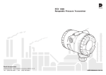
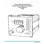
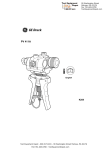
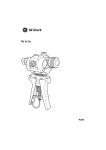
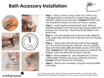
Druck PV 411 Pneumatic/Hydraulic Hand-pump User Manual © Druck Limited 2000 This document is the property of Druck Limited and may not be copied or otherwise reproduced, communicated in any way to third parties, nor stored in any Data Processing System without the express written authorisation of Druck Limited. K258 Issue No. 1 Druck PV 411 User Manual Introduction This technical manual provides operating instructions for the PV 411 Pneumatic/hydraulic hand-pump compatible with the requirements of line operation. Safety The manufacturer has designed this equipment to be safe when operated using the procedures detailed in this manual. The user must not use this equipment for any other purpose than that stated. Only use hydraulic fluids stated in the specification. This manual contains safety and operating instructions which must be followed to make sure of safe operation and to keep the equipment in a safe condition. The safety instructions are either warnings or cautions issued to protect the user and the equipment from injury or damage. Use suitably qualified personnel and good engineering practice for all procedures in this manual. Pressure Do not apply pressure greater than the safe working pressure stated in the specification. Technical advice For technical advice contact the manufacturer or subsidiary. +- This product meets the essential requirements of the relevant EEC directives. Page i K258 Issue No. 1 Druck PV 411 User Manual ABBREVIATIONS The following abbreviations are used in this publication. Note Abbreviations are the same in the singular and plural. °C BSP cm °F inHg lbs ISO kg m mbar mm mmH2O NPT PRV psi PTFE SAE UUT degrees Celsius British standard pipe thread centimetre degrees Fahrenheit inches of mercury pounds International Standards Organisation kilogram metre millibar millimetre millimetres of water National pipe thread pressure relief valve pounds per square inch polytetraflouroethylene Society of Automotive Engineers Unit under test Symbols The following symbols mark this equipment: Read the manual before use. Refer to the manual. K258 Issue No. 1 Page ii Druck PV 411 User Manual CONTENTS Title page Introduction ............................................................................................... 1 Pneumatic pump .................................................................................... 1 Hydraulic pump ...................................................................................... 1 Specification ........................................................................................... 3 Operation ............................................................................................... 4 Pressure/vacuum configuration ............................................................. 4 Connecting the pump ....................................................................... 5 Selector valve ................................................................................... 5 Scissor-action handles limit adjuster ................................................ 6 Pneumatic Operation ........................................................................................ 7 Volume adjuster ................................................................................ 7 Generating pneumatic pressure and vacuum ................................... 8 Pressure ............................................................................................ 8 Vacuum ............................................................................................. 8 Hydraulic Operation ........................................................................................ 10 Fluid reservoir ....................................................................................... 10 Fitting ......................................................................................... 12 Filling ......................................................................................... 12 Priming the system .............................................................................. 13 Vacuum priming ......................................................................... 13 Pre-filling .................................................................................... 14 Setting pressure relief valve ................................................................ 14 Generating hydraulic pressure ............................................................. 15 Multimedia ........................................................................................... 16 Flushing ..................................................................................... 16 Fault finding .......................................................................................... 17 Approved service agents ..................................................................... 18 Annex A Returned Goods Procedure ................................................................. 19 ILLUSTRATIONS Figure 1 2 title page General view ............................................................................... 2 Fitting the reservoir ................................................................... 11 Page iii K258 Issue No. 1 Druck PV 411 User Manual Introduction The PV 411 hand-pump generates either pneumatic pressure and vacuum or hydraulic pressure. The scissor-action handles provide pneumatic pressure and vacuum generation and, in the hydraulic mode, provides hydraulic pressure generation for system priming. Pneumatic pump (Figure 1) A selector valve vents the system, to atmosphere, between selections of pressure and vacuum. Operating the scissor-action handles provides the pumping stroke, for pressure generation. A volume adjuster allows small adjustments of the system pressure. Hydraulic pump (Figure 1) The selector valve vents the system, to the reservoir, between selections of pressure and vacuum (used in the priming process). The volume adjuster generates the required system pressure. A fluid reservoir, screwed into the inlet port on the top of the handpump completes the hydraulic circuit. A pressure relief valve can be set to limit maximum pressure between 30 to 700 bar. Page 1 K258 Issue No. 1 Druck PV 411 User Manual Figure 1, General view K258 Issue No. 1 Page 2 Druck PV 411 User Manual Specification Pressure range Pneumatic ......................................................................... 0 to 60 bar Vacuum .................................................................. 0 to -0.95 bar * Hydraulic ....................................................................... 0 to 700 bar Maximum safe working pressure ........................................... 700 bar Hydraulic fluid .................................................. Demineralised water or mineral-based oils Hydraulic fluids must be compatible with: Stainless steel, anodised aluminium, nitrile rubber, PTFE, polypropylene, delrin, acrylic and nylon. Pressure connections: ................................. 1/4 BSP parallel female Weight (approximate): .............................................................. 1.1 kg Dimensions Length ............................................................................ 260 mm Width ............................................................................ 135 mm Depth .............................................................................. 95 mm * This value assumes atmospheric pressure at 1 bar and will vary depending on atmospheric pressure. Page 3 K258 Issue No. 1 Druck PV 411 User Manual Operation WARNINGS 1 BEFORE APPLYING PRESSURE, MAKE SURE ALL CONNECTIONS ARE CORRECT AND EQUIPMENT IS INTERNALLY CLEAN AND FREE FROM DAMAGE. 2 MAKE 3 DO 4 Note SURE THAT ALL EQUIPMENT IS TO THE CORRECT PRESSURE RATING. NOT EXCEED THE MAXIMUM OPERATING PRESSURE STATED IN THE SPECIFICATION. OBSERVE THE RELEVANT HEALTH AND SAFETY PRECAUTIONS. Wherever possible, use o-ring seals in the connection ports this is the recommended method of sealing. Pressure/vacuum Configuration (Figure 1) In pressure mode, air/fluid is drawn in through the inlet port on the top of the pump and forced out through the two outlet ports. In vacuum mode, the air/fluid flow is reversed as air/fluid is drawn in through the top and rear outlet ports and expelled through the inlet port. K258 Issue No. 1 Page 4 Druck PV 411 User Manual Connecting the Pump Connections can be made to the pump either directly or using the range of adaptors supplied in the optional test kit. Direct The ports can be fitted with any suitable length 1/4 BSP male connector, sealing either with an o-ring at the bottom of the port or a bonded seal at the top. Fit a suitable blanking plug to an unused port. Swivel Adaptors The single, 1/4 BSP, swivel adaptor connects with a range of fixed adaptors. Using the knurled grip-feature, hand-tighten (clockwise) the swivel adaptor, until it is fully inserted. Swivel pump head The pump head swivels through 140° providing optimum viewing angle and bench-top operation. Placing the pump on the bench allows greater force to be applied to the scissor-action handles. Internal stops prevent further rotation of the pump head. Note Do not use excessive force when rotating the pump head. Selector Valve Pressure Turn the selector valve fully clockwise (in) position. Vacuum Turn the selector valve fully anti-clockwise (out) position. Page 5 K258 Issue No. 1 Druck PV 411 User Manual Vent Slowly turn the selector valve to the centre position. C AUTION: A VOID DAMAGING THE INSTRUMENT UNDER TEST BY USING THE VOLUME ADJUSTER TO RELEASE HYDRAULIC PRESSURE. Scissor-action Handles Limit Adjuster Turning the adjuster anti-clockwise reduces the stroke, turning the limit adjuster clockwise increases the stroke. For maximum pneumatic pressure generation, turn the limit adjuster fully clockwise. K258 Issue No. 1 Page 6 Druck PV 411 User Manual Pneumatic Operation Volume Adjuster The volume adjuster can be used in different modes: Low pressure With the selector valve set to vent (open), turn the volume adjuster fully anti-clockwise (out). Turn the selector valve to the fully clockwise (in) position to select pressure. Turn the volume adjuster clockwise to generate pressure. High pressure Turn the volume adjuster to the mid-position. In this position fine adjustments of the generated pressure can be made. Using the scissor-action handles, generate the approximate pressure; then turn the volume adjuster clockwise (in) to increase the pressure or turn the volume adjuster anti-clockwise (out) to decrease the pressure. Vacuum Turn the selector valve fully anti-clockwise (out) position. Turn the volume adjuster to the mid-position. In this position fine adjustments of the generated vacuum can be made. Using the scissor-action handles, generate the approximate vacuum; then turn the volume adjuster clockwise (in) to decrease the vacuum or turn the volume adjuster anti-clockwise (out) to increase the vacuum. For low vacuum use the volume adjuster only. Page 7 K258 Issue No. 1 Druck PV 411 User Manual Generating pneumatic pressure and vacuum Connect the pump as detailed on page 5. Notes Compressing a gas generates heat. Gas heated or cooled in an enclosed volume causes a pressure change. It is important to allow enough time for the heated gas to cool and the pressure to stabilize. The number of pumps required to generate a pressure depends on the volume of the system. Therefore, keep the system volume to a minimum. Pressure 1 Turn the selector valve fully clockwise (in) position. 2 Operate the scissor-action handles to generate the approximate pressure, allow time for thermal stabilization. 3 If necessary, use the volume adjuster to adjust the required pressure. 4 After attaining the required pressure operate the scissoraction handles to generate a higher pressure. Alternatively, vent the pressure to atmosphere by slowly turning (anti-clockwise) the selector valve to the centre position. Vacuum 1 Turn the selector valve fully anti-clockwise (out) position. 2 Operate the scissor-action handles to generate the approximate vacuum, allow time for thermal stabilization. 3 If necessary, use the volume adjuster to adjust the required vacuum. K258 Issue No. 1 Page 8 Druck PV 411 User Manual 4 After attaining the required vacuum operate the scissor-action handles to generate a higher vacuum. Alternatively, vent atmosphere into the vacuum by slowly turning (anti-clockwise) the selector valve to the centre position. After completion, depressurize the pump and disconnect from the pipes and equipment. Page 9 K258 Issue No. 1 Druck PV 411 User Manual Hydraulic Operation CAUTIONS / / / / DO NOT MIX HYDRAULIC FLUIDS . O NLY USE COMPATIBLE FLUIDS , REFER TO THE SPECIFICATION . O NLY FIT APPROPRIATE SEALS ON CONNECTIONS . O BSERVE ABSOLUTE CLEANLINESS WHEN USING THIS PUMP . D AMAGE CAN BE CAUSED IF EQUIPMENT CONNECTED TO THIS PUMP IS CONTAMINATED . Note AVOID PARTICULATE CONTAMINATION. Wherever possible, use o-ring seals in the connection ports, this is the recommended method of sealing. Fluid Reservoir (Figure 2) The main body of the reservoir is transparent acrylic providing a clear view of the contents. The reservoir can be removed from the pump without the need to empty the fluid, a self-sealing connection prevents leakage. The spring-loaded top cover seals under atmospheric pressure conditions, but vents excess internal pressure harmlessly in the event of inadvertent pressurization. The reservoir, connects to the inlet port on the top of the pump and supplies fluid to the pump system for pressure generation. In vacuum mode, used in priming, the fluid flow is reversed, fluid is drawn from the two outlet ports and through to the inlet port and the reservoir. K258 Issue No. 1 Page 10 Druck PV 411 User Manual Figure 2, Fitting the Reservoir Page 11 K258 Issue No. 1 Druck PV 411 User Manual Fitting Make sure that the correct o-ring seal is fitted to the inlet port to prevent leakage. Screw the reservoir (clockwise) into the inlet port. Note: Demineralised water is used to test the pump at manufacture. On shipment, there will be traces of demineralised water in the system. Filling Unscrew the reservoir cover lock nut and remove the reservoir cover. Using clean, recommended fluid fill the reservoir to approximately 2/3 full. Refit the reservoir cover and re-tighten the reservoir cover lock nut. Connect the required pipes and equipment to the outlet ports. K258 Issue No. 1 Page 12 Druck PV 411 User Manual Priming the system There are two methods: vacuum priming to extract the air or prefilling the system. Notes: 1 If air remains in the system, full pressure cannot be achieved as the air in the fluid compresses. Air must be removed from the system fluid. 2 Both priming methods require the pump to be held in the vertical position to keep the reservoir bleed hole in fluid. Do not allow air to enter the system through this bleed hole. Vacuum priming (Figure 2) Connect the equipment as detailed on page 5. Air can be removed using the vacuum facility on the pump. Note: This method should not be used with vacuum-sensitive equipment. Turn selector valve fully out, anti-clockwise (vacuum position). Pump until bubbles stop appearing in the reservoir, (this generates a vacuum in the system). Turn the selector valve fully in, (this action releases the vacuum and rapidly fills the system with fluid from the reservoir). The pump and connected system is ready for use. Page 13 K258 Issue No. 1 Druck PV 411 User Manual Pre-filling Connect the equipment as detailed on page 5. Turn the selector valve fully clockwise (in) position. Loosen the reservoir cover lock nut to open the reservoir cover and let atmospheric pressure into the top of the reservoir. Open the bleed valve on the UUT. Carefully operate the scissor-action handles to fill the system. Stop pumping when fluid comes out of the bleed valve. Close the bleed valve on the UUT. If necessary, top-up the reservoir to the 2/3 level with clean fluid. Secure the reservoir cover by tightening the reservoir cover lock nut. The pump and connected system is ready for use. Setting Pressure Relief Valve (Figure 1) The pressure relief valve (PRV) can be set at pressures from 30 to 700 bar. If the system pressure exceeds the set pressure, the PRV opens and vents fluid through the inlet port to the reservoir. When the pressure decreases, the PRV closes. To set the PRV, loosen the PRV locking screw and turn the PRV to release at the required pressure. Hold the PRV and turn the collar fully anti-clockwise. Tighten the PRV locking screw. K258 Issue No. 1 Page 14 Druck PV 411 User Manual Generating Hydraulic Pressure Note Pressurizing a fluid generates heat. A fluid heated or cooled in an enclosed volume causes a pressure change. Allow enough time thermally stabilize. Open the selector valve anti-clockwise 1 turn. Screw the volume adjuster fully out (anti-clockwise). Close the selector valve. Use the scissor-action handles to generate the initial pressure. Then turn the volume adjuster clockwise to generate the required pressure, allow time for thermal stabilization. To reduce the pressure, turn the volume adjuster out (anticlockwise) to the required pressure. After completion, turn the volume adjuster fully out (anti-clockwise) and turn the selector valve to depressurize the pump. Disconnect from the pipes and equipment. Page 15 K258 Issue No. 1 Druck PV 411 User Manual Multimedia Changing from fluid to gas: Turn the volume adjuster fully clockwise (in). Use the vacuum selection, operate the scissor-action handles to draw fluid into the reservoir. Depressurize the pump. Unscrew and remove the reservoir. Invert the pump and, using the vacuum selection, operate the scissor-action handles to draw residual fluid out through the inlet port. WARNING: W HEN OUTLET PORTS ARE OPEN AND WITH THE SELECTOR VALVE SET TO PRESSURE , OPERATING THE SCISSOR-ACTION HANDLES RAPIDLY EXPELS FLUID. Pneumatic venting, after fluid use, can generate a fluid mist spray out of the inlet port. Flushing If necessary, use soapy water to remove any oil residue. K258 Issue No. 1 Page 16 Druck PV 411 User Manual Fault Finding If system pressure reduces, check the following: 1. Check the selector valve is in the correct position and properly tightened. 2. Allow sufficient time after pressure generation for the temperature to stabilize. 3. Check the adaptors, flexible pipe and connections between the pump and equipment under test for leaks. Tighten any loose joints and replace any seals that are worn or damaged. 4. In hydraulic mode, if the volume adjuster can be wound fully in, but maximum pressure cannot be achieved, there is probably air trapped in the system. Re-prime, and repeat. If, for any reason, a fault occurs within the pump, it is recommended that the equipment be returned to an appointed agent. Page 17 K258 Issue No. 1 Druck PV 411 User Manual Approved Service Agents The following are approved agents for the servicing of Druck products. France Japan Druck SA., 19 Rue Maurice Pellerin, 92600 Asnières, France. Tel: (1) 43 34 24 75 Fax: (1) 43 34 86 08 Druck Japan KK, Medie Corp Building 8, 2-4-14 Kichijyoji-Honcho, Musashino, Tokyo 180, Japan. Tel: (81) 422 20 7123 Fax: (81) 422 20 7155 Germany Druck Messtechnik GmbH, Auf dem Hohenstein 7, 61231 Bad Nauheim, Germany. Tel: (6032) 93300 Fax: (6032) 933080 Holland Druck Nederland b.v., Postbus 232, Zuideinde 37, 2991 Lj Barendrecht, The Nederlands. Tel: (01806) 11555 Fax: (01806) 18131 Italy UK Druck Limited, Fir tree Lane Groby, Leicester LE6 0FH England. Tel: (0116) 231 7100 Fax: (0116) 231 7103 USA Druck Incorporated, 4 Dunham Drive, New Fairfield, Connecticut 06812, U.S.A. Tel: (203) 746 0400 Fax: (203) 746 2494 Druck Italia Srl., Via Capecelatro 11, 20148 Milano, Italy. Tel: (02) 48707166 Fax: (02) 48705568 K258 Issue No. 1 Page 18 Druck PV 411 User Manual Annex A Returned goods procedure Should the unit become unserviceable and require repair it can be returned to the Druck Service Department. Please contact our Service Department, either by 'phone or fax, to obtain a Returned Goods Authorization (RGA) number, providing the following information: Product (i.e. PV 411) Pressure medium (i.e. pneumatic, hydraulic ) Serial number Details of defect/work to be undertaken Operating conditions Safety Precautions You must also tell us if the product has been in contact with anything hazardous or toxic and the relevant COSH references and precautions to be taken when handling. Important notice Service by unauthorized sources will affect the warranty and may not guarantee further performance. Page 19 K258 Issue No. 1