1
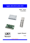
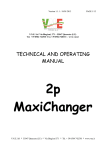
MR-compatible LED light
User Manual
1. Intended use
The LED light is intended to be used in combination with our MR compatible video cameras for
different illumination purposes like face monitoring or eye-tracking. It emits diffuse light.
The LED light can be used inside an MRI scanner without perturbing artifacts even in fMRI. The
device uses a single light-emitting-diode (LED) in a compact titanium housing.
The device does not have an alert in case of a breakdown. Thus, it should not be used to observe
vital functions without other measures.
2. Description
The light source is composed of an LED in a titanium housing, a connection cable (see figure 1), and
a control and filter box (see figure 2). It can be equipped with different types of LEDs. Thus, it is
possible to provide both, visible or infrared light.
Figure 1:
The photograph shows the LED light
(arrow) mounted together with MRC's
MR-compatible camera “12M”.
The powering is arranged via the filter box. The LED is connected to the filter box with a shielded
cable that includes the power and the signal lines.
MR_CAM_LED-Light_Manual_v2.sxw
MG – 15.10.2010
version: 2
page 1 of 3
Status:approved
3. Installation of the filter box
The filter box should be mounted to the filter panel of the MR cabinet. It must be located outside the
MR cabinet. The cable to the LED must be guided into the MR cabinet through a hole.
For permanent installation the filter box should be screwed onto the panel board by means of the
feed-through LED connector.
•
A 10 mm through-hole is required in the filter panel.
•
The LED connector is guided through this hole.
•
The connector serves also as a connection to the shielding (ground) of the MR cabinet.
For temporary use, the LED cable can be brought into the MR cabinet by other means, e.g. through
a service entry hole. In this case, an additional grounding cable should be used to connect the LED
box connector to the shield panel grounding.
4. Operation
The intensity can be adjusted by means of a potentiometer at the filter box.
Figure 2:
Control and filter box. In front the
potentiometer for the intensity adjustment
can be seen. Besides the potentiometer is
a LED which shines when the device is
powered.
The connector for the power supply is on
the left side.
The feed-through LED connector for
the connection of the LED cable is on the
back side. The connector should be used
to screw the box to the filter panel.
5. Labelling
MR_CAM
LIGHT EL
SN: 100929SF015
Supply: 6VDC 200mA
MRC Systems GmbH
Hans-Bunte-Str. 10
D-69123 Heidelberg
Germany
Power consumption: max. 200 mA / 6V
MR_CAM_LED-Light_Manual_v2.sxw
MG – 15.10.2010
version: 2
page 2 of 3
Status:approved
6. Notes for safety and operation
•
Whenever metallic parts are used in an MRI scanner there is a residual risk of an
electric discharge from this part to the human body. Therefore we strongly advice
not to place the LED closer to the subject or the user than 10 cm.
•
The risk of an electric discharge can be further reduced if the connection cable is
guided on a direct way (without loops and without crossing the middle axis) out
of the bore.
•
Even during a temporary use of the LED light source (when the LED connection
cable is guided through a service entry hole or a waveguide) please take care that
(1) the filter box is grounded on the MR shield. The earth ground cable must
have a good contact
(2) the LED connection cable does not protrude from the MR cabinet /
waveguide. Otherwise the cable can cause interference.
•
Light-emitting diodes (LEDs) are subject to an aging process which is accelerated
if the LEDs are driven at highest powers. In order to increase the lifetime of the
product we recommend not to drive the light source with highest intensity and to
diconnect it from mains whenever it is not in use.
•
The LED light source is not specially protected against splash water. It should
only be used in dry environments. If moisture is entrapped into the housing a short
circuit can occur leading to a damage of the electronics.
•
Please do not use any other power supply than the medical one included in
delivery.
6. Contact
MRC Systems GmbH
Hans-Bunte-Strasse 10
D-69123 Heidelberg
Germany
Phone: +49-6221-13803-00
Fal: +49-6221-13803-01
E-mail:[email protected]
MR_CAM_LED-Light_Manual_v2.sxw
MG – 15.10.2010
version: 2
page 3 of 3
Status:approved