1
User manual
Technical parameters
Energy measuring device
EDEBDA0193-4314-1_EN
multimess
1D4
Your partner for
network analysis
System I English
© KBR Kompensationsanlagenbau GmbH
Subject to technical changes
2
Introduction
KBR multimess 1D4
EDEBDA0193-4314-1_EN
Introduction............................................................................................................... 5
User manual................................................................................................................ 5
Intended use............................................................................................................... 5
Explanation of safety relevant symbols .......................................................... 6
Safety notes................................................................................................................. 7
Product liability......................................................................................................... 8
Disposal....................................................................................................................... 8
Range of functions ................................................................................................... 9
multimess 1D4-BS with multimess 1F96-DS................................................... 9
multimess 1D4-BS with multisio 6D6 and
multisio 6F96-DS.....................................................................................................10
multimess 1D4-BS with multisys 3D2-ESBS...................................................10
Device overview .....................................................................................................11
Installation.................................................................................................................14
Device assembly .....................................................................................................14
Connections..............................................................................................................15
Start-up.......................................................................................................................16
Start-up of the multimess 1D4 with
multimess 1F96-DS display.................................................................................16
Start-up of the multimess 1D4 at the
multisio 6D6 with multisio 6F96-DS ................................................................19
Start-up of the multimess 1D4 with
multisys 3D2-ESBS..................................................................................................20
System operation ...................................................................................................20
Configuration of system parameters
in the Extras menu .................................................................................................20
Commi function ......................................................................................................22
Para function ........................................................................................................... 22
Consumption monitoring ...................................................................................22
Menu overview....................................................................................................... 24
Technical data of the measuring module...................................................... 28
Measuring accuracy...............................................................................................28
Measuring principle.............................................................................................. 28
Device memory .......................................................................................................29
Power supply ...........................................................................................................29
Hardware inputs and outputs.............................................................................29
Inputs...........................................................................................................................29
Outputs ..................................................................................................................... 29
Electrical connection.............................................................................................30
Mechanical data.......................................................................................................30
V1.00
3
KBR multimess 1D4
EDEBDA0193-4314-1_EN
Standards and miscellaneous.............................................................................31
Technical data of the measuring module...................................................... 32
Power supply ...........................................................................................................32
Hardware inputs and outputs.............................................................................32
Electrical connection.............................................................................................32
Mechanical data.......................................................................................................32
Standards and miscellaneous............................................................................ 33
Protective measures...............................................................................................33
Overvoltage and lightning protection............................................................33
Index........................................................................................................................... 34
4
V1.00
KBR multimess 1D4
Introduction
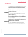
1 Introduction
Thank you for choosing this KBR quality product. In order to familiarize
yourself with the operation and configuration of the device, we
recommend that you read this manual thoroughly, so that you are
able to make use of the entire range of functions of this high-quality
product.
The individual chapters serve to explain the technical details of
the device and show how to avoid damage by means of proper
installation and commissioning.
1.1 User manual
This user manual describes the multimess 1D4 device version with
multimess 1F96-DS display.
This user manual is included in the scope of delivery of the device
and must be accessible for the user at all times (e.g. in the switchgear
cabinet). Even when the device is resold to third parties, the manual
remains part of the device.
Although we used the utmost care in assembling this user manual, we
would like to thank you in advance for notifying us about any errors or
ambiguous descriptions you might notice.
1.2 Intended use
EDEBDA0193-4314-1_EN
This device is intended for measuring electrical parameters via
external transformers in the low-voltage network (400VAC Ph-Ph).
V1.00
5
KBR multimess 1D4
Introduction
1.3 Explanation of safety relevant symbols
This user manual contains notes that must be observed for your
personal safety and to avoid damage to equipment.
i
These notes are identified by an
or information symbol,
depending on the degree of hazard they represent.
j
Warning
"Warning" means that death, major injuries or damage may occur in
case the appropriate safety measures are not taken.
h Caution
"Caution" means that minor injuries or damage may occur in case the
appropriate safety measures are not taken.
i Note
"Note" is an important information on the product, its operation or the
respective part of the user manual to which special reference is made.
The content of this user manual has been carefully reviewed in terms
of the hardware and software described. Certain deviations, however,
cannot be excluded, and the manufacturer is not liable for complete
conformity. The specifications made in this user manual are checked
on a regular basis, necessary corrections will be included in the next
revision.
6
V1.00
EDEBDA0193-4314-1_EN
Disclaimer
Introduction
KBR multimess 1D4
1.4 Safety notes
In order to prevent operating errors, operation of this device is
kept as simple as possible. This way, you will be able to quickly start
working with the device.
In your own interest, however, you should read the following
safety notes carefully. During assembly, the applicable DIN / VDE
regulations must be observed!
Power supply connection, setup and operation of the device must
be performed by qualified personnel only. Qualified personnel in
accordance with the safety notes in this user manual are persons
authorized to set up, ground and mark devices, systems and circuits
in accordance with the applicable standards and regulations.
To avoid fire and electrical shock, the device must not be exposed to
rain or humidity!
Before connecting the device to the power supply, check whether
the local power supply conditions comply with the specifications on
the nameplate.
A faulty connection can lead to the destruction of the device!
When connecting the device, observe the connection chart (see
chapter “Connection chart”) and make sure that no voltage is applied
to the connection lines. Only use proper wiring material and observe
the correct polarity when wiring!
In order to ensure proper and safe operation of the product, it must
be transported, stored, installed and assembled in accordance with
the specifications and operated and maintained carefully.
A visibly damaged device must generally be considered unfit for use
and disconnected from the power supply!
Error detection, repair and maintenance work may only be carried
out in our facilities or after contacting the service team.
EDEBDA0193-4314-1_EN
Unauthorized opening of the device voids any warranty. Correct
operation can no longer be guaranteed!
Opening the device may expose live parts. Capacitors in the device
may still be loaded, even if the device has been disconnected from
all voltage sources. It is generally not allowed to operate an open
device!
V1.00
7
KBR multimess 1D4
Introduction
I n systems susceptible to lightning, lightning protection must be
provided for all input and output lines (for recommendations, see
chapter “Protective measures”)!
1.5 Product liability
You have acquired a high quality product. In its manufacture, only
components of the highest reliability and quality were used. Each
device is subject to long-term testing before it is delivered. Regarding
product liability, we refer to our general terms and conditions for
electronic equipment, which you can find at www.kbr.de . The
warranted characteristics of the device only apply for operation in
accordance with its intended use!
1.6 Disposal
EDEBDA0193-4314-1_EN
Defective, outdated or no longer used devices must be properly
disposed of. At your request, we will dispose of the devices for you.
8
V1.00
Insert battery
KBR multimess 1D4
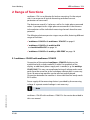
2 Range of functions
multimess 1D4 is a multimeter for busbar mounting. On the output
side, it can measure all typical alternating and direct current
parameters of consumers.
The device can record 1x 3-phase as well as 3x single-phase measured
values. A prerequisite for single-phase measurement is that the neutral conductors of the individual measuring channels have the same
potential.
The following device expansion stages are possible, featuring different
ranges of function:
“multimess 1D4-BS with multimess 1F96-DS” on page 9
“multimess 1D4-BS with multisio 6D6
and multisio 6F96-DS” on page 10
“multimess 1D4-BS with multisys 3D2-ESBS” on page 10
2.1 multimess 1D4-BS with multimess 1F96-DS
Connection of the optional multimess 1F96-DS display can be
established with a ready-made RJ12 cable. For operation of the
display, an additional power supply unit is needed, e. g. the multisys
1D4-PS-24V. This way, no complicated wiring of voltage and current
paths from the converter to the switchgear cabinet door is necessary.
Up to 10 measuring modules can be read out and displayed.
Connection between the modules is also established via ready-made
RJ12 cables.
Power supply of the measuring device is provided by the measuring
voltage. A separate control voltage is not necessary.
i Note
EDEBDA0193-4314-1_EN
multimess 1D4-BS with multimess 1F96-DS is the version described in
this user manual.
V1.00
9
KBR multimess 1D4
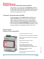
2.2 multimess 1D4-BS with multisio 6D6 and multisio 6F96-DS
If the multimess 1D4 is connected to the multisio 6D6 instead of to
the display, the multisio 6D6 creates a load profile memory (P+ P-/ Q+
Q-) and an eBus interface. Five measuring modules can be connected
to each central storage module Connection between the modules is
established via ready-made RJ12 cables.
2.3 multimess 1D4-BS with multisys 3D2-ESBS
For direct connection of the multimess 1D4 to the KBR eBus, the
multisys 3D2-ESBS gateway is required, which also provides the
supply voltage for the module bus interface via ready-made RJ12
cables. A maximum of 15 measuring modules can be connected
(power consumption of the measuring module interface approx. 0.3
W, power output of the multisys 3D2-ESBS gateway approx. 5 W at 24
VDC). For a larger number of measuring modules, the multisys 1D4-PS24V power supply unit is required (power output 24 VDC, 10 W).
3 Device overview
multimess 1D4 measuring module
For busbar assembly (7.5 mm rail)
Connection to measuring voltage Ph-N 230 VAC
Measuring current connection via transformer
x/1A or x/5A
Plug terminal connection 2.5 mm2
RJ12 module bus connection for
supply voltage of the bus interface /
connection of additional measuring modules.
Recording of momentary current
and voltage values.
Continuous energy meter for active and
reactive energy
10
V1.00
EDEBDA0193-4314-1_EN
RJ12 display connection
KBR multimess 1D4
multimess 1F96-DS
Display illumination (Dot Matrix 128x96)
Brightness and contrast adjustable
Display dimming time adjustable
(energy saving function)
Operation via sensor buttons
Mounting depth 40 mm
Door assembly cut-out 92x92 mm
Module bus connection RJ12 for measuring
modules and supply voltage
Display of momentary current and voltage
values
Continuous energy meter for active and
reactive energy
Management of up to 10 measuring modules
Assignment of station names to the measuring
modules
EDEBDA0193-4314-1_EN
Display language selectable
German ("deut") / English ("engl")
V1.00
11
KBR multimess 1D4
3.1 Operating structure
The following overview gives
you an idea of the multimess
1D4 operating structure with the
1F96-DS display. For a detailed
description, please refer to
“Menu overview” on page 24.
Instantaneous value display
U PH-N measuring module 1
Module name
Voltage channel 1
Voltage channel 2
Voltage channel 3
Additional
measuring
modules
U PH-PH measuring module 1
Module name
Voltage channel 1
Voltage channel 2
Voltage channel 3
Additional
measuring
modules
Apparent current meas. module 1
Module name
Apparent current channel 1
Apparent current channel 2
Apparent current channel 3
Additional
measuring
modules
Total power
Module name
Apparent power
Active power
Reactive power
Additional
measuring
modules
Apparent power meas. module 1
12
Additional
measuring
modules
EDEBDA0193-4314-1_EN
Module name
Apparent power channel 1
Apparent power channel 2
Apparent power channel 3
V1.00
KBR multimess 1D4
Active power meas. module 1
Module name
Active power channel 1
Active power channel 2
Active power channel 3
Additional
measuring
modules
Reactive power meas. module 1
Module name
Reactive power channel 1
Reactive power channel 2
Reactive power channel 3
Additional
measuring
modules
Cosine Phi measuring module 1
Module name
Cosine Phi channel 1
Cosine Phi channel 2
Cosine Phi channel 3
Additional
measuring
modules
Frequency
Module name
Network frequency
Additional
measuring
modules
Energy meter:
Continuous counter
active energy
Continuous counter
reactive energy
EDEBDA0193-4314-1_EN
Extras (Settings)
Display firmware version
Commissioning
Configuration
V1.00
Additional
measuring
modules
Commissioning
Configuration
Password
Module name
Scan / remove module
Reset display
Single-phase / 3-phase measurement
Transformer I 1 / 2
Transformer U 1 / 2
Display firmware module
Measuring module selection
LCD contrast
LCD brightness
LCD dimmer brightness
Dimmer delay
Display test
Language selection
13
KBR multimess 1D4
4 Installation
In this chapter, you will find a description of:
“Device assembly” on page 14
“Connections” on page 15
“Commissioning” on page 16
4.1 Device assembly
During installation, the applicable DIN / VDE regulations must
be observed! Before connecting the device to the power supply,
check whether the local power supply conditions comply with the
specifications on the nameplate. A faulty connection may destroy
the system! The device must be connected in accordance with the
connection chart. For energy and synchronous pulse input, polarity
must be observed (contact your energy supplier).
EDEBDA0193-4314-1_EN
In systems susceptible to lightning, lightning protection must be
provided for the control voltage, bus line and pulse lines (e.g. energy
supplier pulse lines from the transformer station to the location of the
energy control system).
14
V1.00
KBR multimess 1D4
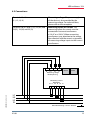
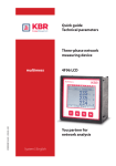
4.2 Connections
Terminals 10 - 13
(L1, L2, L3, N)
Measuring voltage. The power supply
of the device is also provided by the
measuring voltage. For technical data,
please refer to the nameplate.
Terminals 20 (k1) and 21 (l1), 22 (k2) and
23(l2), 24 (k3) and 25 (l3)
Measuring inputs for current. The
measuring inputs for current must be
connected via current transformers
x/1A AC or x/5A AC. When connecting
transformers, pay attention to the energy
flow direction and the correct assignment
of measuring voltage inputs to the current
transformers.
13
12
11
10
N
L3
L2
L1
Measuring voltage
Messspannung
Modul
Modul
Measuring current
Messstrom
k1 l1 k2 l2 k3 l3
EDEBDA0193-4314-1_EN
20 21 22 23 24 25
L1
L2
L3
N
Stromflussrichtung / current direction
V1.00
15
KBR multimess 1D4
4.3 Start-up
The following section describes the start-up procedure for the
different device versions.
4.3.1 Start-up of the multimess 1D4 with multimess 1F96-DS display
For starting up the multimess 1D4 with multimess 1F96-DS display,
please proceed as follows:
1. Connect the measuring module to the multimess 1F96-DS display
via the module bus interface.
2. With the "Module out" connector, connect the measuring module to
the multisys 1D4-PS-24V power supply unit via the second module
bus interface.
3. At the multisys 1D4 power supply unit, connect the supply voltage
(refer to nameplate). The operation LED on the device is illuminated
green.
4. At the terminals 10 (L1), 11 (L2), 12 (L3) and 13 (N), connect the
measuring voltage (the operating voltage of the measuring
module).
5. At the display, select the menu Extras > Commissioning to scan
measuring modules connected.
6. Displayed are modules already existing, as well as the menu items
"scan" and "rem." (for removing measuring modules from the
module bus list).
EDEBDA0193-4314-1_EN
7. After selection of the menu item "scan", the scan mode is activated
and the function LED at the measuring modules flashes slowly.
16
V1.00
KBR multimess 1D4
8. At the measuring module, the scan sensor button (close to the
status LED, flashing green) is unlocked.
9. To set the measuring module into scan mode, touch the scan
sensor button for about 4 seconds (the green status LED flashes
more quickly)
10. The multimess display recognizes the measuring module and adds
it to the list of modules connected.
11. You can now scan further modules, which are automatically
added to the module list or, by touching the stop button, end the
scanning process. The display can manage a maximum number of
ten modules.
Set-up diagram for operation of the
multimess 1D4 with multimess 1D4-DS (example):
LCD
multisys
1D4-PS-24V
power supply
unit
Measuring module 1
to 10 (maximum)
Modul
in
Modul
out
multisys 1D4-PS24V
EDEBDA0193-4314-1_EN
_
+
101 102
24V DC
V1.00
L
1
N PE
2 PE
85 - 260V AC
Netz / Power
17
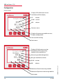
KBR multimess 1D4
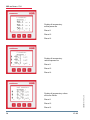
Configuration
Extras menu
Display of the firmware version
and release of the display
DSdisplay
01.00version
005release
Previous menu
Display of measuring module version,
Display configuration
Start commissioning
Next menu
Display of the firmware version
and release of the measuring
module at the module bus
Measuring module designation
BS type module bus device
01.00 version
Selection of next measuring module
Selection of previous measuring module
Next menu
18
V1.00
EDEBDA0193-4314-1_EN
001release
KBR multimess 1D4
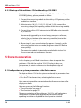
4.3.2 Start-up of the multimess 1D4
at the multisio 6D6 with multisio 6F96-DS
For starting up the multimess 1D4 at the multisio 6D6, please proceed
as follows:
1. Connect the measuring module to the multisio 6D6 via the module
bus interface.
2. At the terminals 10 (L1), 11 (L2), 12 (L3) and 13 (N), connect the
measuring voltage (the operating voltage of the measuring
module).
3. On the display, select the menu Settings > Module management.
4. Displayed are the multisio basic module as well as modules already
existing and the menu item "scan".
5. After selecting this menu item with the cursor buttons, the scan
mode can be started with the scan button and the scan display
begins to flash. This way, the scan button at the measuring module
(close to the status LED, flashing green) is unlocked.
6. By pressing the scan sensor button for approx. 4 seconds, set the
measuring module into scan mode (the green status LED flashes
more quickly).
The multisio basic module now recognizes the measuring module and
adds it to the list of modules connected.
You can now scan further modules, which are automatically added
to the module list or, by touching the stop button, end the scanning
process. The multisio 6D6 can manage a maximum number of ten
modules.
EDEBDA0193-4314-1_EN
You can now read out and process the data.
V1.00
19
KBR multimess 1D4
4.3.3 Start-up of the multimess 1D4 with multisys 3D2-ESBS
For starting up the multimess 1D4 at the KBR eBus via the multisys
3D2-ESBS gateway, please proceed as follows:
1. Connect the measuring module to the multisys 3D2 gateway via the
module bus interface.
2. A
t the terminals 10 (L1), 11 (L2), 12 (L3) and 13 (N), connect the
measuring voltage (the operating voltage of the measuring module).
3. Connect the multisys 3D2 gateway to the KBR eBus using terminals
90, 91 and 92.
A command, triggered by the visual energy computer software,
unlocks the scan button at the measuring module (close to the
status LED, flashing green).
4. By pressing the scan sensor button for approx. 4 seconds, set the
measuring module into scan mode (the green status LED flashes
more quickly).
The measuring module is detected and included in the bus list.
You can now read out and process the data.
5 System operation
In this chapter, you will find instructions on how to operate the
multimess 1D4 with the multisio 1D4-DS display in daily use.
Furthermore, it contains references to the complete range of
functions.
5.1 Configuration of system parameters in the Extras menu
To adapt multimess 1D4 to the system monitored, its parameters have
to be configured.
Press the F1 key eleven times, selecting the Extras menu.
You have access to the following functions:
“Commi function” on page 22
“Para function” on page 22
The menu navigation of the multimess 1D4-DS is self-explanatory.
The operator is guided and supported by the device through
operating instructions displayed for the respective situation.
20
V1.00
EDEBDA0193-4314-1_EN
Here, measuring modules connected and the firmware version of the
display are shown.
KBR multimess 1D4
The following signs and abbreviations
will be used in the display:
Scroll forward (through main menu or submenu)
Scroll backwards (through main menu or submenu)
EDEBDA0193-4314-1_EN
Return
Next measuring module
Previous measuring module
Value input
Select next screen
Return for configuration
Perform configuration
Fundamental power factor
Voltage phase / neutral conductor
Network frequency
Active power – total (3-phase)
QS
Active power / reactive power / apparent power – total (3-phase)
YES Confirmation to save configuration
NO Discard configuration
SCAN
Scan mode (search mode) for module search
Firmware Operating software of the measuring module or display module
1x3p
3-phase measurement
3x1p
single-phase measurement
Measuring voltage transformer 1 / 2
Main current transformer 1 / 2
LCD LCD parameter (display module)
code
Password protection
reset
Reset function display
V1.00
21
KBR multimess 1D4
5.1.1 Commissioning function
With the commissioning start-up function, up to 10 measuring
modules connected can be integrated.
This includes:Password protection for configuration
Assigning names to individual measuring modules
Scan menu for reading in measuring modules
connected
Removing measuring modules connected
Selection of single-phase or 3-phase measurements
Configuration of current transformer
primary / secondary
Configuration of voltage transformer
primary / secondary
i
Note
Single-phase or 3-phase measurement:
Ensure that you match the current transformer inputs to the correct
measurement phases.
Each phase is recorded and displayed individually for both
measurement methods.
For the single-phase totals of apparent, active and reactive power,
the measured values of the individual phases are added.
For 3-phase measurements, the total power values are calculated
(3-phase current value).
5.1.3 Para function
5.1.4 Consumption monitoring
In this operating mode, momentary measured values as well as
continuous meters for active and reactive energy consumption can be
read out directly at the display.
22
V1.00
EDEBDA0193-4314-1_EN
With the "para" configuration function, you can display the firmware
version of the measuring modules connected, change the LCD
settings and choose between English and German as the display
language.
KBR multimess 1D4
The respective module name is included
on each screen, depending on the
measuring module selected.
The following momentary values
can be displayed:
1st screen:Voltage Ph-N for phase L1, L2
and L3 individually
2nd screen:Voltage Ph-Ph for phase L1-2,
L2-3 and L3-1 individually
3rd screen:Apparent current for phase
L1, L2 and L3 individually
4th screen:Total power
for apparent, active and
reactive power
5th screen:Apparent power for phase
L1, L2 and L3 individually
6th screen:Active power for phase
L1, L2 and L3 individually
7th screen:Reactive power for phase
L1, L2 and L3 individually
8th screen:Cosine Phi for phase
L1, L2 and L3 individually
9th screen:Power frequency
EDEBDA0193-4314-1_EN
10th screen:Continuous energy meter
for active energy
consumption
Continuous energy meter
for reactive energy
consumption
11th screen:Commissioning
(Extras menu)
LCD parameters
V1.00
23
KBR multimess 1D4
6 Menu overview
In this chapter, you will find a complete overview of all menus and
menu items of the multimess.
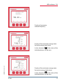
Display of momentary
measuring voltage for
Phase L1-N
Phase L2-N
Phase L3-N
EDEBDA0193-4314-1_EN
Display of momentary
measuring voltage for
Phase L1-2
Phase L2-3
Phase L3-1
24
V1.00
KBR multimess 1D4
Display of momentary
apparent current for
Phase L1
Phase L2
Phase L3
Display of total values of
Apparent power
Active power
Reactive power
EDEBDA0193-4314-1_EN
Display of momentary
apparent power for
Phase L1
Phase L2
Phase L3
V1.00
25
KBR multimess 1D4
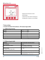
Display of momentary
active power for
Phase L1
Phase L2
Phase L3
Display of momentary
reactive power for
Phase L1
Phase L2
Phase L3
EDEBDA0193-4314-1_EN
Display of momentary values
of cosine Phi for
Phase L1
Phase L2
Phase L3
26
V1.00
KBR multimess 1D4
Display of momentary
network frequency
Display of the continuous energy meter
for active energy (total value).
()
EDEBDA0193-4314-1_EN
In the submenus
, the values of the
individual phases can be seen.
Display of the continuous energy meter
for reactive energy (total value).
()
In the submenus
, the values of the
individual phases can be seen.
V1.00
27
KBR multimess 1D4
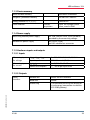
Display of the firmware version
of the display.
Furthermore, the Commissioning and
Configuration submenus are included.
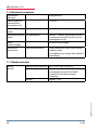
7 Technical data
7.1 Technical data of the multimess 1D4 measuring module
7.1.1 Measuring accuracy
Current
± 0.5 % / ± 1 digit
Voltage
± 0.5 % / ± 1 digit
Apparent power
± 1 % / ± 1 digit
Active power
± 1 % / ± 1 digit
Reactive power
± 1 % / ± 1 digit
Frequency
± 0.1 Hz / ± 1 digit
Reading
128 measured values per period
A/D converter
12 bit
Measurement of U and I
simultaneous recording of
measured values for U and I;
Update speed
(complete measuring cycle)
< 1 sec.
Harmonics calculation
DFT with 128 points over one period
Frequency measurement
Mode: Voltage measured
between phase L1, L2, L3 – N
28
EDEBDA0193-4314-1_EN
7.1.2 Measuring principle
V1.00
KBR multimess 1D4
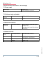
7.1.3 Device memory
Main and data memory
16kB RAM unbuffered
Program / parameter memory
256 kB Flash / 4kB EEP
Energy counter P+, P-, Q+, Q-
saved in EEP
Limit violation
Time for
acquisition
8 min. for average current
value, saved in RAM
7.1.4 Power supply
Measuring module power supply
50...230...280 VAC Ph-N, 3,2VA, 50/60 Hz,
provided by the measuring voltage
Module bus power supply
ext. 24VDC, 0.3W,
via RJ12 module bus connector
7.1.5 Hardware inputs and outputs
7.1.5.1 Inputs
Measuring inputs
for voltage
Measuring inputs
for current
UL1-N ; UL2-N ; UL3-N
3 x 50V...230V...280V AC, 50/60 Hz
Input impedance
900 kOhm each (Ph-N)
IL1; IL2; IL3
3 x 0,02A...5A...6A AC
Power consumption
<_ 0.3 VA per input at 6A
Module bus
RS485 via RJ12 interface
Baud rate
38400
Addressing
Can be addressed using the display or
visual energy (connection via multisio
3D2 ESBS gateway)
7.1.5.2 Outputs
EDEBDA0193-4314-1_EN
Serial
interface
V1.00
29
KBR multimess 1D4
7.1.6 Electrical connection
Connection
elements
Plug terminals
Permissible cross
section of the
connection lines
2.5 mm2
Measuring voltage
inputs
Fuse protection
max. 6 A
Measuring current
inputs
Fuse protection
NONE!!! Always short-circuit current
transformer terminals k and l prior to
opening the circuit!
Input
control voltage
Module bus
connection
via measuring voltage
Connection material
ready-made KBR system cable (6 pole
modular cable,
unshielded), max. length 30m if placed
accordingly
7.1.7 Mechanical data
Housing measurements
90 x 71 x 61 mm (H x W x D)
Mounting type
Wall mounting on DIN rail 7.5mm deep,
in accordance with DIN EN 50022
Suitable for distribution board
mounting
Weight
approx. 175g
EDEBDA0193-4314-1_EN
Busbar
devices
30
V1.00
KBR multimess 1D4
7.1.8 Standards and miscellaneous
Environmental
conditions
DIN EN 60721-3-3/A2: 1997; 3K5+3Z11;
(IEC721-3-3; 3K5+3Z11)
Operating temperature
-5°C … +55°C
Humidity
5% … 95% non-condensing
Storage temperature
-25°C … +70°C
Standards and
amendments
DIN EN 61010: 2001 +B1: 2002; +B2:
2004
Protection class
II
Overvoltage
category
CAT III: UPH-PH up to 400V
Degree of protection
IP 20
DIN EN 60529:1991 +A1:2000
Electromagnetic
compatibility
DIN EN 61000-6-1: 2007,
DIN EN 61000-6-2: 2005,
DIN EN 61000-6-3: 2007,
DIN EN 61000-6-4: 2007
EDEBDA0193-4314-1_EN
Electrical
safety
Standards and
amendments
V1.00
31
KBR multimess 1D4
7.2 Technical data of the multimess 1D4-DS display
7.2.1 Power supply
Power supply
ext. 24VDC, 1W,
via RJ12 module bus connector
7.2.2 Hardware inputs and outputs
Serial
interface
Module bus
RS485 via RJ12 interface
Baud rate
38400
7.2.3 Electrical connection
Module bus
connection
Connection material
ready-made KBR system cable (6 pole
modular cable,
unshielded), max. length 30m if placed
accordingly
7.2.4 Mechanical data
Housing dimensions
96 x 96 x 46 mm (H x W x D)
Mounting cutout
92 x 92 mm (according to
manufacturer’s specifications)
Protection type
Front IP 51
Weight
approx. 175g
EDEBDA0193-4314-1_EN
Flush-mounted
device
32
V1.00
KBR multimess 1D4
7.2.5 Standards and miscellaneous
Environmental
conditions
Electrical
safety
Standards and
subsequent
amendments
DIN EN 60721-3-3/A2: 1997; 3K5+3Z11;
(IEC721-3-3; 3K5+3Z11)
Operating temperature
-5°C … +55°C
Humidity
5% … 95%, non-condensing
Storage temperature
-25°C … +70°C
Standards and
subsequent
amendments
DIN EN 61010-1/A2: 1996-05;
(IEC1010-1/A2)
Protection type
IP20 in accordance with DIN EN 40050
part 9: 1993-05
Electromagnetic
compatibility
DIN EN 61000-6-3: 2005-06;
(IEC 61000-6-3)
DIN EN 61000-6-2: 2000-03;
(IEC 61000-6-2)
7.3 Protective measures
7.3.0.1 Overvoltage and lightning protection
EDEBDA0193-4314-1_EN
It is recommended to install overvoltage protection measures to protect our high-quality
devices from damage. We also recommend to protect control voltage inputs and pulse
lines, if required.
V1.00
33
KBR multimess 1D4
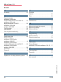
8 Index
A
Assembly . . . . . . . . . . . . . . . . . . . . . . . . . . . . . 14
C
Commissioning
multimess 1D4 at the
multisio 6D6 with multisio 6F96-DS . . . . 19
multimess 1D4 with
display multimess 1F96-DS . . . . . . . . . . . . 16
multimess 1D4 with
multisys 3D2-ESBS . . . . . . . . . . . . . . . . . . . . . 20
Configuration . . . . . . . . . . . . . . . . . . . . . . . . . 18
Connections . . . . . . . . . . . . . . . . . . . . . . . . . . . 15
Consumption monitoring . . . . . . . . . . . . . . 22
D
Device overview . . . . . . . . . . . . . . . . . . . . . . . 10
Device versions
multimess 1D4-BS with
multimess 1F96-DS . . . . . . . . . . . . . . . . . . . . . . 9
multimess 1D4-BS with
multisio 6D6 and multisio 6F96-DS . . . . . 10
multimess 1D4-BS with
multisys 3D2-ESBS . . . . . . . . . . . . . . . . . . . . . 10
Disclaimer . . . . . . . . . . . . . . . . . . . . . . . . . . . . . . . 6
Disposal . . . . . . . . . . . . . . . . . . . . . . . . . . . . . . . . . 8
E
Explanation of safety relevant symbols . . . 6
F
Function
Commi . . . . . . . . . . . . . . . . . . . . . . . . . . . . . . . . 22
Para . . . . . . . . . . . . . . . . . . . . . . . . . . . . . . . . . . . 22
I
Intended use . . . . . . . . . . . . . . . . . . . . . . . . . . . . 5
M
Measuring inputs for current . . . . . . . . . . . 15
Measuring voltage . . . . . . . . . . . . . . . . . . . . 15
Menu overview . . . . . . . . . . . . . . . . . . . . . . . . 24
P
Programming . . . . . . . . . . . . . . . . . . . . . . . . . . 20
Product liability . . . . . . . . . . . . . . . . . . . . . . . . . 8
Protective measures . . . . . . . . . . . . . . . . . . . 33
S
Safety notes . . . . . . . . . . . . . . . . . . . . . . . . . . . . . 7
Set-up diagram
multimess 1D4 with multimess 1D4-DS 17
T
Technical data . . . . . . . . . . . . . . . . . . . . . . . . . 28
Terminals . . . . . . . . . . . . . . . . . . . . . . . . . . . . . 15
U
EDEBDA0193-4314-1_EN
User manual . . . . . . . . . . . . . . . . . . . . . . . . . . . . . 5
34
V1.00
Am Kiefernschlag 7
D-91126 Schwabach,
Germany
Phone +49 9122 6373 - 0
Fax
+49 9122 6373 - 83
[email protected]
www.kbr.de
EDEBDA0193_1112-1_EN
KBR Kompensationsanlagenbau GmbH