1
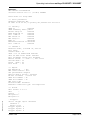
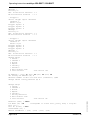
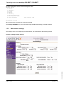
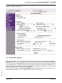
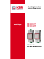
Operating instructions Technical Parameter multisys 3D2-ESET 3D2-BSET Interfaces for KBR eBus and MODULBUS KBR GmbH Am Kiefernschlag 7 D-91126 Schwabach T +49 (0) 9122 6373-0 F +49 (0) 9122 6373-83 E info@kbr,de www.kbr.de Preface Dear Customer We would like to thank you for choosing a KBR GmbH quality product. In order to familiarize yourself with the operation and programming of the device and always be able to use the whole functionality of this high-quality product, we recommend that you read this manual thoroughly. The individual chapters serve to explain the technical details of the device and show how to avoid damage by means of proper installation and commissioning. The manual is included in the scope of delivery of the device and must be accessible for the user at all times (e.g. in the switchgear cabinet). Even when the device is resold to third parties, the manual remains part of the device. Although we used the utmost care in assembling this manual, we would like to thank you in advance for notifying us about any errors or ambiguous descriptions that might be in it. You will find a form for corrections in the appendix. Sincerely, 2009-1 GB KBR GmbH Schwabach Page I von IV Safety Precautions Safety Precautions This manual contains notes that must be observed for your personal safety and to avoid damage to equipment. Notes are identified by a warning sign or an info symbol according to the degree of hazard they represent. Danger means that death, major injuries or damage will occur in case the appropriate safety measures are not performed. Warning means that death, major injuries or damage may occur in case the appropriate safety measures are not performed. Caution means that minor injuries or damage may occur in case the appropriate safety measures are not performed. Note is an important information on the product, product handling or the respective part of the user manual to which special reference is made. Disclaimer The contents of this manual has been checked with the described hardware and software components. Certain deviations, however, cannot be excluded, so the manufacturer is not liable for complete conformity. The specifications made in this manual are checked on a regular basis, necessary corrections are included in the next revision. We appreciate your corrections and comments. © KBR-GmbH Subject to change 2009-1 GB Page II von IV Safety Precautions General Safety Precautions In order to prevent operating errors, handling of the device is kept as simple as possible. This way, you will be able to use the device very soon. In your own interest, however, you should read the following safety precautions carefully. Warning During installation, the applicable DIN / VDE regulations must be observed! Mains connection, setup and operation of the device must only be performed by qualified personnel. Qualified personnel as understood in the safety precautions of this manual are persons authorized to setup, ground and mark equipment, systems and wiring systems in accordance with applicable standards. To avoid the hazard of fire and electrical shock, the device must not be subjected to rain or other humidity! Before the device is connected to the mains, you will have to check whether the local mains conditions comply with the specifications on the manufacturer's label. A wrong connection may destroy the device! When connecting the device, the connection chart must be observed (see chapter "Connection chart") and the connection lines must be powerless. Only use proper line material and watch the correct polarity when wiring! In order to ensure proper and safe operation of the product, it must be transported, stored, installed and mounted in accordance with the specifications and operated and maintained carefully. A device showing visible damage must by all means be considered as unfit for operation and must be disconnected from the mains! Error detection, repairs and maintenance work may only be carried out in our facilities or after contacting our service team. Every warranty obligation of the manufacturer expires if the device is opened without written consent from our service team. Proper operation can no longer be guaranteed! Opening the device may expose parts under voltage. Capacitors in the device may still be loaded even if the device was disconnected from all voltage sources. It is generally not allowed to operate the open device! 2009-1 GB In facilities subject to hazard of lightning, lightning protection must be provided for all input and output lines (recommendations see chapter "Protective measures")! Page III von IV Product Liability / Disposal Product Liability With these product, you have acquired a quality product. In its manufacture, only components of the highest reliability and quality were used. Each device is subject to long-term testing before it is delivered. For information on product liability, please refer to our General Terms and Conditions for electronic devices. The warranted properties of the device apply only if it is operated in accordance with its intended use! Disposal Please dispose of defective, outdated or no longer used devices properly. At your request, we will be pleased to dispose of the devices for you. 2009-1 GB Page IV von IV Operating instructions multisys 3D2-ESET / 3D2-BSET Table of Contents 1 multisys 3D2-ESET / 3D2-BSET ........................................................... 2 1.1 LAN and KBR eBus RS-485 interfaces (multisys 3D2-ESET) ........................... 2 1.2 LAN and Modulbus RS-485 interfaces (multisys 3D2-BSET) ........................... 3 1.3 LAN eBus configuration via Ethernet interface (Telnet) ................................... 4 1:3:1 Procedure for IP address 192.168.0.1 or unknown IP............................................... 4 1:3:2 Procedure for IP address 0.0.0.0 ................................................................................ 4 1:3:3 Menu item 0 Server , setting IP address .................................................................... 7 1:3:4 Menu item 1 Channel 1, setting of serial interface (KBR eBus)............................... 7 1:3:5 Web browser settings ..................................................................................................8 1.4 Box-to-Box operation ........................................................................................... 9 1:4:1 Setting the multisys 3D2-ESET in master operation ...............................................10 1:4:2 Setting the multisys 3D2-ESET in slave operation ................................................. 11 1:4:3 Web browser settings ................................................................................................12 1:4:4 Resetting the multisys 3D2-ESET from master to slave operation .......................13 1:4:5 Web browser settings ................................................................................................15 1.5 2 Connection diagram ........................................................................................... 17 Technical Data ..................................................................................... 18 Power supply ...................................................................................................... 18 2.2 Electrical connection .......................................................................................... 18 2.3 Mechanical data .................................................................................................. 18 2.4 Standards and Miscellaneous ........................................................................... 18 EDEBDA0190 / 2911-1 GB 2.1 Version 1.00 Page 1 of 18 Operating instructions multisys 3D2-ESET / 3D2-BSET 1 multisys 3D2-ESET / 3D2-BSET The multisys 3D2-ESET connects the KBR eBus to your computer via Ethernet. On the Energy Bus side, it acts as master, and on the Ethernet side, it acts as slave. The two interfaces (RS-485 on the KBR eBus side and Ethernet on the network side) are galvanically separated. The multisys 3D2-BSET connects the KBR Modulbus to your computer via Ethernet. On the Modulbus side, it acts as master, and on the Ethernet side, it acts as slave. The two interfaces (RS-485 on the Modulbus side and Ethernet on the network side) are galvanically separated. If necessary, the RS-485 interface on the KBR eBus side, or respectively on the Modulbus side, can be terminated using four DIP switches (terminating resistors fitted into the multisys). The device is equipped with a "power" LED for supply voltage monitoring. The multisys 3D2-ESET is equipped with a power supply (85 to 265V AC/DC; 2VA) and is suitable for wall mounting on a DIN rail 7.5 mm deep, in accordance with DIN EN50022 (for distribution board mounting). b 1.1 Note The Ethernet interface settings for the multisys 3D2-ESET and multisys 3D2-BSET are identical. LAN and KBR eBus RS-485 interfaces (multisys 3D2-ESET) The RS-485 interface is set to the KBR eBus parameters 38400 baud, 8 data bits, parity even, 1 stop bit. If necessary, it can be terminated using four DIP switches. RS-485 RS-485 for the KBR eBus (3 pole multi-pin connector, 3.5 mm) Terminal No. 90 = Ground, 91 = A, 92 = B (in accordance with KBR terminology) DIP switch for the termination of RS-485: DIP1 and DIP2 ON, DIP3 OFF = Fail-safe active DIP1 and DIP2 OFF, DIP3 ON = Termination active DIP1 and DIP2 OFF, DIP3 OFF = no fail-safe, no Termination DIP4 not assigned! Note: Fail-safe termination may only be active once in a bus segment! LED for monitoring power supply RJ-45 Ethernet connection Supply voltage 85 - 265V AC/DC; 2VA (2 pole multi-pin connector, 5 mm) Power Page 2 of 18 EDEBDA0190 / 2911-1 GB LAN Version 1.00 Operating instructions multisys 3D2-ESET / 3D2-BSET The operating status of the LAN interface (XPort) is indicated by two LEDs: Connection LED (left) Activity LED (right) Off No connection Off No activity Yellow 10 Mbps Yellow Half duplex Green 100 Mbps Green Full duplex 1.2 LAN and Modulbus RS-485 interfaces (multisys 3D2-BSET) The Modbus interface is set to the Modbus parameters 38400 baud, 8 data bits, parity even, 1 stop bit. If necessary, it can be terminated using four DIP switches. RJ-12 RJ-12 for the KBR Modulbus DIP switch for the termination of RS-485: DIP1 and DIP2 ON, DIP3 OFF = Fail-safe active DIP1 and DIP2 OFF, DIP3 ON = Termination active DIP1 and DIP2 OFF, DIP3 OFF = no fail-safe, no Termination DIP4 not assigned! Note: Fail-safe termination may only be active once in a bus segment! LED for monitoring power supply RJ-45 Ethernet connection Supply voltage 85 - 265V AC/DC; 2VA (2 pole multi-pin connector, 5 mm) Power EDEBDA0190 / 2911-1 GB LAN Version 1.00 Page 3 of 18 Operating instructions multisys 3D2-ESET / 3D2-BSET 1.3 LAN eBus configuration via Ethernet interface (Telnet) The Ethernet interface of the multisys LAN eBus can be set up using the Ethernet interface via Telnet or the Lantronix tool DeviceInstaller. b Note On delivery, the devices are set to the IP address 192.168.0.1. For this reason, it is recommended to check whether the device can be reached using this IP address. Depending on the IP address, the following procedures are possible: 1.3.1 Procedure for IP address 192.168.0.1 or unknown IP. The device can be configured using the Lantronix tool "DeviceInstaller". Go to: http://ltxfaq.custhelp.com/cgi-bin/ltxfaq.cfg/php/enduser/std_adp.php?p_faqid=644 (Feburary 23th, 2009) and download and install the Microsoft .NET Framework version 2.0 and Lantronix DeviceInstaller (first install Microsoft's .NET Framework version 2.0). After starting DeviceInstaller, the network connected is scanned, and the detected Lantronix ports are displayed and can then be edited. 1.3.2 Procedure for IP address 0.0.0.0: For the Ethernet address 0.0.0.0, access to the module has to be enabled first. (prerequisite: MAC ID known). The MAC ID can be gathered from a label attached to the side of the device, e.g. 00-20-4a-86-c9-91. However, this procedure only works if the device does not have an IP address yet (0.0.0.0). 1. Connect the network cable to an existing network, or directly connect it to a computer using a crosslink cable. 2. Have the network administrator give you a network address. 3. Open DOS input window (with Start->All Programs->Accessories>Command Prompt). 4. Connect network address using MAC ID (command arp -s): Example: Input: arp -s 10.66.22.98 00-20-4a-86-c9-91 Input: telnet 10.66.22.98 1 Response: Establishing connection with 10.66.22.98... Connection to host could not be established; port 1: connection could not be established Page 4 of 18 EDEBDA0190 / 2911-1 GB Input: telnet 10.66.22.98 9999 Input: Enter (within 2 seconds) Version 1.00 Operating instructions multisys 3D2-ESET / 3D2-BSET Response: MAC address 00204AA6C991 Software version V6.5.0.7 (070919) XPTEXE Press Enter for Setup Mode *** basic parameters Hardware: Ethernet TPI IP addr 10.66.22.98, no gateway set,netmask 255.255.255.0 *** Security SNMP is SNMP Community Name: Telnet Setup is TFTP Download is Port 77FEh is Web Server is Web Setup is ECHO is Enhanced Password is Port 77F0h is enabled public enabled enabled enabled enabled enabled disabled disabled enabled *** Channel 1 Baudrate 38400, I/F Mode 7F, Flow 00 Port 08000 Connect Mode : C0 Send '+++' in Modem Mode enabled Show IP addr after 'RING' enabled Auto increment source port disabled Remote IP Adr: --- none ---, Port 00000 Disconn Mode : 00 Flush Mode : 80 Pack Cntrl : 20 *** Expert TCP Keepalive : 45s ARP cache timeout: 600s CPU performance: Regular Monitor Mode @ bootup : enabled RS-485 tx enable : active low HTTP Port Number : 80 SMTP Port Number : 25 MTU Size: 1400 Alternate MAC: disabled Ethernet connection type: auto-negotiate EDEBDA0190 / 2911-1 GB *** E-mail Mail server: 0.0.0.0 Unit : Domain : Recipient 1: Recipient 2: - Trigger 1 Serial trigger input: disabled Channel: 1 Match: 00,00 Trigger input1: X Trigger input2: X Trigger input3: X Version 1.00 Page 5 of 18 Operating instructions multisys 3D2-ESET / 3D2-BSET Message : Priority: L Min. notification interval: 1 s Re-notification interval : 0 s - Trigger 2 Serial trigger input: disabled Channel: 1 Match: 00,00 Trigger input1: X Trigger input2: X Trigger input3: X Message : Priority: L Min. notification interval: 1 s Re-notification interval : 0 s - Trigger 3 Serial trigger input: disabled Channel: 1 Match: 00,00 Trigger input1: X Trigger input2: X Trigger input3: X Message : Priority: L Min. notification interval: 1 s Re-notification interval : 0 s Change Setup: 0 Server 1 Channel 1 3 E-mail 5 Expert 6 Security 7 Defaults 8 Exit without save 9 Save and exit Your choice ? 0 IP Address : (000) 10.(000) 66.(000) 22.(000) 98 Set Gateway IP Address (N) N Netmask: Number of Bits for Host Part (0=default) (0)8 Change telnet config password (N) N Change Setup: 0 Server 1 Channel 1 3 E-mail 5 Expert 6 Security 7 Factory defaults 8 Exit without save 9 Save and exit Your choice ? 1 Page 6 of 18 Version 1.00 EDEBDA0190 / 2911-1 GB Baudrate (9600) ? 38400 I/F Mode (4C) ?7F corresponds to 8 data bits, parity even, 1 stop bit Flow (00) ? Port No (10001) ? 8000 ConnectMode (C0) ? Remote IP Address : (000) .(000) .(000) .(000) Operating instructions multisys 3D2-ESET / 3D2-BSET Remote Port (0) ? DisConnMode (00) ? FlushMode (00) ? DisConnTime (00:00) ?: SendChar 1 (00) ? SendChar 2 (00) ? Change Setup: 0 Server 1 Channel 1 3 E-mail 5 Expert 6 Security 7 Factory defaults 8 Exit without save 9 Save and exit Your choice ? 9 Parameters stored ... Connection to host lost. You can now change the settings and save them entering 9. The device can now be operated using the new network parameters. The IP address, Default Gateway and Netmask are set under the 0 Server menu item. The serial interface (KBR eBus) is set up under the 1 Channel 1 menu item (eBUS parameters 38400 baud, 8 data bits, parity even, 1 stop bit). 1.3.3 Menu item 0 Server , setting IP address IP address (10) etc. Example: 10.66.22.98 Set Gateway IP Address (N) ? N Gateway IP addr ( 0) ( 0) ( 0) ( 0) Netmask: Number of Bits for Host Part (0=default) (8) Change telnet config password (N) N When entering the netmask, observe the following chart: EDEBDA0190 / 2911-1 GB 1.3.4 Network Class Host Bits Netmask A 24 255.0.0.0 B 16 255.255.0.0 C 8 255.255.255.0 Menu item 1 Channel 1, setting of serial interface (KBR eBus): Baud rate (38400) ? 38400 I/F Mode (7C) ? 7F // the parameters 8 data bits, parity even, 1 stop bit correspond to the 7F coding Flow (00) ? Port No (10001) ? 8000 Version 1.00 Page 7 of 18 Operating instructions multisys 3D2-ESET / 3D2-BSET All other parameters of this menu item stay the same. Change Setup: 0 Server 1 Channel 1 3 E-mail 5 Expert 6 Security 7 Factory defaults 8 Exit without save 9 Save and exit Your choice ? 9 Parameters stored ... When entering 9, the changes are saved and accepted. The multisys 3D2-ESET can now be accessed using the KBR Visual Energy computer software. 1.3.5 Web browser settings The settings, which can be adjust by the Web Interface, are documented in the following pictures. Channel 1 settings / Serial settings. EDEBDA0190 / 2911-1 GB Page 8 of 18 Version 1.00 Operating instructions multisys 3D2-ESET / 3D2-BSET Channel 1 settings / Connection. 1.4 Box-to-Box operation EDEBDA0190 / 2911-1 GB In Box-to-Box operation, you can establish a logical permanent network connection between two multisys 3D2-ESET serial ports. In this operating mode, there is a permanent online connection between the two serial terminals connected. Possible additional data traffic or other network protocols do not influence the connection. In this operating mode, a permanent TCP connection between the master and slave port is established. The master port is acting as a TCP client and thus responsible for opening (after configuration or reset) and closing (after deactivating the "Box-to-Box" operating mode) tasks. On the network side, there is only multisys 3D2-ESET data traffic using the Box-to-Box connection if serial reference data is available. There is no data traffic excessing the TCP protocol. Version 1.00 Page 9 of 18 Operating instructions multisys 3D2-ESET / 3D2-BSET 1.4.1 Setting the multisys 3D2-ESET in master operation Example: Master IP address 10.66.22.90 Menu 1 Channel 1 * For the operating mode "Box-to-Box", only the master port is configured; The slave IP address (remote IP address) and slave port number (remote port) are only set at the master port! * The configuration of the serial interface in the 0 Server sub menu has to be made at both ports. Input: telnet 10.66.22.90 9999 Input: Enter (within 2 seconds) Response: MAC address 00204AA63735 Software version V6.5.0.7 (070919) XPTEXE Press Enter for Setup Mode *** basic parameters Hardware: Ethernet TPI IP addr 10.66.22.90, no gateway set,netmask 255.255.255.0 *** Security SNMP is SNMP Community Name: Telnet Setup is TFTP Download is Port 77FEh is Web Server is Web Setup is ECHO is enabled public enabled enabled enabled enabled enabled disabled Enhanced Password is disabled Port 77F0h is enabled *** Channel 1 Baudrate 38400, I/F Mode 7F, Flow 00 Port 08000 Connect Mode : C0 Send '+++' in Modem Mode enabled Show IP addr after 'RING' enabled Auto increment source port disabled Remote IP Adr: --- none ---, Port 00000 Disconn Mode : 00 Flush Mode : 00 usw. Page 10 of 18 EDEBDA0190 / 2911-1 GB Change Setup: 0 Server 1 Channel 1 3 E-mail 5 Expert 6 Security 7 Defaults 8 Exit without save 9 Save and exit Your choice ? 1 Version 1.00 Operating instructions multisys 3D2-ESET / 3D2-BSET Baudrate (38400) ? I/F Mode (7F) ? Flow (00) ? Port No (8000) ? ConnectMode (C0) ? C3 Start Char: (02) ? 02 Send '+++' in Modem Mode(Y) ? Show IP addr after 'RING' (Y) ? Auto increment source port (N) ? Remote IP Address : (000) 10.(000) 66.(000) 22.(000) 98 Remote Port (0) ? 8000 Slave-Port DisConnMode (00) ? FlushMode (00) ? 80 Pack Cntrl (00) ? 20 DisConnTime (00:00) ?00:20 SendChar 1 (00) ? SendChar 2 (00) ? Change Setup: 0 Server 1 Channel 1 3 E-mail 5 Expert 6 Security 7 Defaults 8 Exit without save 9 Save and exitYour choice ? Slave-IP-Adresse 9 When entering 9, the changes are saved and accepted. 1.4.2 A description of how to set up the multisys 3D2-ESET in slave operation is given in section 1.3. EDEBDA0190 / 2911-1 GB * Setting the multisys 3D2-ESET in slave operation Version 1.00 Page 11 of 18 Operating instructions multisys 3D2-ESET / 3D2-BSET 1.4.3 Web browser settings The settings, which can be adjust by the Web Interface, are documented in the following pictures. Channel 1 settings / Serial settings. EDEBDA0190 / 2911-1 GB Page 12 of 18 Version 1.00 Operating instructions multisys 3D2-ESET / 3D2-BSET Channel 1 settings / Connection. 1.4.4 Resetting the multisys 3D2-ESET from master to slave operation Example: Master IP address 10.66.22.90 To reset a multisys 3D2-ESET configured as master to slave for "normal" network operation, you have to change the parameter in the 1 Channel 1 menu as follows: Input: telnet 10.66.22.90 9999 Input: Enter (within 2 seconds) EDEBDA0190 / 2911-1 GB Response: MAC address 00204AA63735 Software version V6.5.0.7 (070919) XPTEXE Version 1.00 Page 13 of 18 Operating instructions multisys 3D2-ESET / 3D2-BSET Press Enter for Setup Mode *** basic parameters Hardware Ethernet TPI IP addr 10.66.22.90, no gateway set,netmask 255.255.255.0 *** Security SNMP is enabled SNMP Community Name:public Telnet Setup is enabled TFTP Download isenabled Port 77FEh is enabled Web Server is enabled Web Setup is enabled ECHO is disabled Enhanced Password isdisabled Port 77F0h is enabled *** Channel 1 Baudrate 38400, I/F Mode 7F, Flow 00 Port 08000 Connect Mode : C3 Send '+++' in Modem Mode enabled Show IP addr after 'RING' enabled Auto increment source port disabled Remote IP Adr: 10.66.22.98, Port 08000 Start Char: 02 Disconn Mode : 00 Disconn Time: 00:20 Flush Mode : 80 Pack Cntrl : 20 etc. Change Setup: 0 Server 1 Channel 1 3 E-mail 5 Expert 6 Security 7 Defaults 8 Exit without save 9 Save and exit Your choice ? 1 Page 14 of 18 EDEBDA0190 / 2911-1 GB Baud rate (38400) ? I/F Mode (7F) ? Flow (00) ? Port No (8000) ? ConnectMode (C3) ? C0 Send '+++' in Modem Mode (Y) ? Show IP addr after 'RING' (Y) ? Auto increment source port (N) ? Remote IP Address : (010) 0.(000) 0.(000) 0.(000) 0 Remote Port (8000) ? 00000 DisConnMode (00) ? FlushMode (80) ? Pack Cntrl (20) DisConnTime (00:20) ?00:00 SendChar 1 (00) ? SendChar 2 (00) ? Version 1.00 Operating instructions multisys 3D2-ESET / 3D2-BSET Change Setup: 0 Server 1 Channel 1 3 E-mail 5 Expert 6 Security 7 Defaults 8 Exit without save 9 Save and exit Your choice ? 9 When entering 9, the changes are saved and accepted. 1.4.5 Web browser settings The settings, which can be adjust by the Web Interface, are documented in the following pictures. EDEBDA0190 / 2911-1 GB Channel 1 settings / Serial settings. Version 1.00 Page 15 of 18 Operating instructions multisys 3D2-ESET / 3D2-BSET Channel 1 settings / Connection. EDEBDA0190 / 2911-1 GB Page 16 of 18 Version 1.00 Operating instructions multisys 3D2-ESET / 3D2-BSET 1.5 Connection diagram EDEBDA0190 / 2911-1 GB * For voltage supply, see nameplate. Version 1.00 Page 17 of 18 Operating instructions multisys 3D2-ESET / 3D2-BSET 2 Technical Data 2.1 Power supply Power supply 2.2 85 - 265V AC/DC ; <10VA Electrical connection Connection elements Plug-in terminals Permissible cross section of the connection lines Power supply 2.5 mm2 , bus connection 1.5 mm2 Input Control voltage max. 6 A Fuse protection LAN connection 8P8C modular connector BUS connection Connection material For proper operation, please only use shielded twisted-pair cables; e.g. IY(St)Y 2x2x0.8 BUS connection multisys 3D2-ESET Pins for BUS connection via RS-485 Device Terminal 90 (⊥) Terminal 91 (A) Terminal 92 (B) BUS connection multisys 3D2-BSET 2.3 Mechanical data Top hat rail device 2.4 6 pole modular cable, RJ-12 connector: 6P6C Housing measures 90 x 36 x 61 mm (H x W x D), Mounting type Wall mounting on DIN rail 7.5 mm deep, in accordance with DIN EN 50022 Suitable for distribution board mounting Weight approx. 120g Standards and Miscellaneous Environmental conditions Standards DIN EN 60721-3-3/A2: 1997-07; 3K5+3Z11; (IEC721-3-3; 3K5+3Z11) Operating temperature - 5°C ….+60°C Humidity Electrical safety 5% …....95% Storage temperature -25°C ….+70°C Standards DIN EN 61010-1: 2002-08; Protection class I in accordance with DIN EN 61010-1 : 2002-08 Mode of protection IP20 in accordance with DIN EN 40050 Part 9: 1993-05 Electromagnetic compatibility DIN EN 61000-6-3: 2005-06; (IEC 61000-6-3) DIN EN 61000-6-2: 2006-03; (IEC 61000-6-2) EDEBDA0190 / 2911-1 GB Page 18 of 18 Version 1.00 ERKLÄRUNG DER KONFORMITÄT DECLARATION OF CONFORMITY DÉCLARATION DE CONFORMITÉ Wir We/Nous KBR GmbH Schwabach (Name des Anbieters / supplier´s name / norm du fournisseur) Am Kiefernschlag 7 D-91126 Schwabach (Anschrift / address / addresse) erklären in alleiniger Verantwortung, dass das (die) Produkt(e) / declare under our sole responsibility that the product(s) / Déclarons sous notre seule responsabilité, ques le(s) produit(s) multisys 3D2-ESET multisys 3D2-BSET (Bezeichnung, Typ oder Modell oder Seriennummer / name, type or model or serial number / nom, type ou modèle, N° de lot ou de série) mit folgenden Europäischen Richtlinien übereinstimmt (übereinstimmen) is (are) in conformity with the following directives / Répondet(ent) aux directives suivantes Niederspannungsrichtline Nr. EMV-Richtlinie Nr. Low Voltage Directive No. Directive Basse Tension N° EMV Directive No. EMV Directive N° 2006/95/EG 2004/108/EG 2006/95/EC 2006/95/CE 2004/108/EC 2004/108/CE Dies wird nachgewiesen durch die Einhaltung folgender Norm(en) This is documented by the accordance with the following standard(s) / Justifié par le respect de la (des) norme(s) suivante(s) DIN EN 61010-1-2001; DIN EN 61010-1/B1:2002 DIN EN 61010-1/B2:2004 DIN EN 61000-6-1:2007 DIN EN 61000-6-2:2005 DIN EN 61000-6-3:2007 DIN EN 61000-6-4:2007 (Titel und/oder Nr. sowie Ausgabedatum der Norm(en) Title and/or number and date of issue of the standard(s) Titre et/ou numéro et date d´édition de la (des) norme(s) Schwabach, 18.07.2011 (Ort und Datum der Ausstellung Place and date of issue Lieu et date de l´édition) Geschäftsführer General manager KBR GmbH Am Kiefernschlag 7 D-91126 Schwabach T +49 (0) 9122 6373-0 F +49 (0) 9122 6373-83 E [email protected] www.kbr.de An KBR GmbH Abteilung Entwicklung Am Kiefernschlag 7 D-91126 Schwabach To KBR GmbH Development Am Kiefernschlag 7 D-91126 Schwabach / Germany Vorschläge: Korrekturen: Betrifft Gerät: Suggestions: Corrections: Device concerned Sollten Sie beim Lesen dieser Bedienungsanleitung oder Druckschrift auf Druckfehler gestoßen sein, bitten wir Sie, uns diese mitzuteilen. Ebenso freuen wir uns natürlich über Anregungen, Hinweise oder Verbesserungsvorschläge. If you come across misprints in this user manual or printed material, please take the time to notify us. We will also be glad to hear your ideas, notes and suggestions for improvement. Bitte geben Sie die betreffende Anleitung oder Druckschrift mit Versionsnummer und/oder Ausgabestand an. Please identify the user manual or printed material in question with version number and/or revision number. Absender / Sender: Name: Firma/Dienststelle, / Copany/Department: Anschrift / Address: Telefon / Phone: Telefax / Fax: email: Korrekturvorschläge zur Bedienungsanleitung / Druckschrift Corrections/Suggestions for user manual / Printed material 1309-1 DE / GB Version