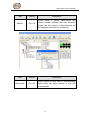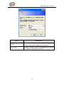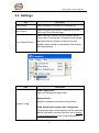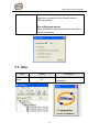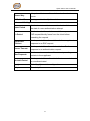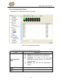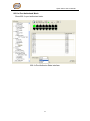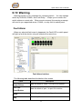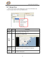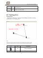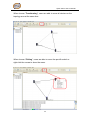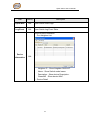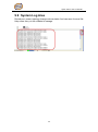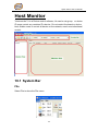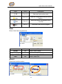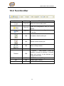
1
Industrial Ethernet Products Management Utility Open-Vision v3.0 User’s Manual Version 1.0 December, 2010. ORing Industrial Networking Corp. 4F., NO.3, Lane 235, Baociao Rd.Sindian City, Taipei County 23145 Taiwan, R.O.C. Tel: + 886 2 2918 3036 Fax: + 886 2 2918 3084 Website: www.oring-networking.com E-mail: [email protected] Open-Vision User‟s Manual Table of Content Getting to Know Your Switch ............................................................................. 3 1.1 About the Open-Vision v3.0 ........................................................... 3 1.2 Install Java machine ....................................................................... 3 1.3 System requirements ...................................................................... 4 1.4 Prepare to install Open-Vision....................................................... 5 Apply Open-Vision Commander to Switch Connection ............................... 11 2.1 Getting start to use Open-Vision Commander.......................... 11 2.2 Make sure PC‟s Network setting ................................................. 12 2.3 2.3.1 2.3.2 How to discover different IP domain device? ............................ 13 In the same broadcast domain .................................................... 13 In the different broadcast domain ............................................... 14 2.4 Open-Vision Main interface ......................................................... 19 System Bar ......................................................................................................... 20 3.1 Task ................................................................................................. 20 3.2 Settings ........................................................................................... 27 3.3 Help ................................................................................................. 28 Function Bar ....................................................................................................... 29 4.1 Icons Introduction .......................................................................... 29 Switch Management Interface ......................................................................... 31 5.1 Devices ........................................................................................... 31 5.2 Status Monitor ................................................................................ 32 5.3 Scan Devices Configuration ........................................................ 33 5.4 Syslog Events ................................................................................ 34 5.5 Wizards ........................................................................................... 35 5.6 Group IP Setting Wizard .............................................................. 35 5.7 Group Firmware Update Wizard ................................................. 38 5.8 Group O-Ring Setting Wizard...................................................... 40 Switch Function Interface ................................................................................. 43 6.1 Basic Setting .................................................................................. 44 6.2 6.3 6.4 6.5 6.6 6.7 Basics & Port Configuration ......................................................... 45 Port Configuration ......................................................................... 62 Redundancy ................................................................................... 67 VLAN ............................................................................................... 72 SNMP Configuration ..................................................................... 77 Traffic Prioritization........................................................................ 81 1 Open-Vision User‟s Manual 6.8 IGMP Snooping ............................................................................. 86 6.9 Security ........................................................................................... 88 6.10 Warning ........................................................................................... 96 6.11 Monitor and Diag ......................................................................... 101 6.12 Save Configuration...................................................................... 106 6.13 Factory Default ............................................................................ 107 6.14 System Reboot ............................................................................ 107 Switch Status Interface ................................................................................... 108 7.1 The GUI for users to get switch status ..................................... 108 Switch Configuration Interface ...................................................................... 109 8.1 The relationship of function interface and the configuration interfaces ................................................................................................... 109 Topology View .................................................................................................. 110 9.1 9.2 9.3 9.4 9.5 9.6 9.7 9.8 About the Topology View ............................................................ 110 Start to use Topology View ......................................................... 110 Topology View Main Interface ................................................... 111 System Bar ................................................................................... 113 Function Bar ................................................................................. 129 Device Tree .................................................................................. 130 Group Tree ................................................................................... 134 Topology Area .............................................................................. 135 9.9 System Log Area ......................................................................... 142 Host Monitor ..................................................................................................... 143 10.1 System Bar ................................................................................... 143 10.2 Function Bar ................................................................................. 145 10.3 Devices Tree ................................................................................ 146 10.4 Monitor Area ................................................................................. 149 MIB Brower ....................................................................................................... 149 TroubleShooting .............................................................................................. 150 11.1 Why Topology View can not run in our computer?................. 150 11.2 License key warning message .................................................. 150 11.3 11.4 SYSLOG warning message ....................................................... 150 Why Topology View can not receive SNMP trap? ............... 151 2 Open-Vision User‟s Manual Getting to Know Your Switch 1.1 About the Open-Vision v3.0 Open-Vision v3.0 is ORing Industrial Networking Corp in 2010 year newly issued the powerful software utility, his function surmounts. Open-Vision v3.0 includes four utilities “Commander” 、 “Topology view” 、 ”Host monitor” 、 MIB Brower, With Open-Vision v3.0 Commander, user can set parameters to multiple switches at the same time. provides a powerful interface for users to manage all switches in the network. Open-Vision v3.0 is not only a powerful utility for users to configure but also a useful utility for monitoring. Users can monitor switches‟ status via Host monitor. When the monitored switches fail, the failure information will be displayed on Host monitoring interface. Open-Vision v3.0 1.2 Install Java machine Please make sure if your computer if install JRE (if not ,Please download Java Runtime Environment (JRE) 6 Update 3 from SUN http://java.sun.com/javase/downloads/index.jsp. 3 Open-Vision User‟s Manual 1.3 System requirements Minimum System RequirementsIV Pentium IV or above (2.0 MHZ or above) VGA Monitor with 1024 x 768 resolution WINDOWS NT,2K ,2K3, XP 512 MB RAM (1 GB recommended) Java 2 Runtime Environment version 1.5 Internet Explorer 6.0 or higher Supported Network Protocols TCP / IP UDP SNMP Operating System Windows NT 2000 2003 XP Vista Windows 7 4 Open-Vision User‟s Manual 1.4 Prepare to install Open-Vision Before using Open-Vision, users need to install the utility first. Double click Open-Vision.exe, started the install process. Step 1 After execution of Open-Vision v3.0.exe, the Operation System start to install Open-Vision v3.0 5 Open-Vision User‟s Manual Step 2 Click [Next] to continue setup process. 6 Open-Vision User‟s Manual Step 3 Users are able to change the path that they want to install in. Click When click to change the path. , users can configure the path that they want to install from the pop-up windows. 7 Open-Vision User‟s Manual Step 4 Completed the path, and then click [Next] 8 Open-Vision User‟s Manual Step 5 Please double check the installing information of this page. If everything is correct, then click “Install.” 9 Open-Vision User‟s Manual Step 6 When the Installation process is finished, click “Finish” to complete the Installing process. 10 Open-Vision User‟s Manual Apply Open-Vision Commander to Switch Connection 2.1 Getting start to use Open-Vision Commander Select 「Start」→「All Programs」→「Open-Vision」→「commander」 to execute Open-Vision v3.0 11 Open-Vision User‟s Manual 2.2 Make sure PC’s Network setting First of all, double check the configuration of the PC‟s IP address, Subnet mask, Default gateway…etc., and make sure the PC is connected to Default Gateway and the switch you wish to connect properly. 12 Open-Vision User‟s Manual 2.3 How to discover different IP domain device? 2.3.1 In the same broadcast domain When the monitored PC and the managed switches are within the same broadcast domain, as illustrated by Figure 1-1, Figure 1-1 Click「Discovery」directly on the Open-Vision to search the switches. 13 Open-Vision User‟s Manual 2.3.2 In the different broadcast domain If the monitored PC and the managed switches are in different broadcast domain, as illustrated by Figure 2-2, then users need to use the advanced search function to search the switches. Figure 2-2 Make sure the PC is connected to Default Gateway and the switch you wish to connect properly. If the Network is proper, open Open-Vision, and click “Discovery Filter.” 14 Open-Vision User‟s Manual Select “Remote” and a window open up as shown below. Insert the Switch IP Address range you wish to search and click IP address will be added automatically as shown in the diagram above. “ok” to start the searching of switch. And the switches in different network will be found by Open-Vision. 15 , the Click Open-Vision User‟s Manual Use the example: Use open vision tool , through Router controls different Domain IP ORing Switch. We must set up Routing Protocol in Router, add we wanted control domain (192.168.1 x, 192.168.20 x, 192.168.30 x) ,Set up finish, Control PC will start routing, after router will finish routing, " Control PC" Can connect as 192.168.1.x, 192.168.20.x, 192.168.30.x, three different domain, open vision too can at the same time management three different domain ORing switch . 16 Open-Vision User‟s Manual 1、 Config router default Routing function , Add 192.168.1.0、 192.168.20.0、192.168.30.0, three kinds of different domain 2、 Use Ping order, " Ping" ORing Switch of three kinds of different Domain, can all join normal Link, Routing succeeds, Command :C:\Ping 192.168.1.10 -t 17 Open-Vision User‟s Manual Command :C:\Ping 192.168.20.20 -t Command :C:\Ping 192.168.20.20 -t 3、 Start open vision, uses Discovery Filter Function, input wanted to scan Domain, as picture shows Scanned and finished, pushed OK, Open Vision and succeeded in detecting and examined to three kinds of different Domain " ORing switch" 18 Open-Vision User‟s Manual 2.4 Open-Vision Main interface The Open-Vision main interface shows as below: System Bar Function Bar Switch Management Interface Switch Function Interface Switch Status Interface Switch Configuration Interface 19 Open-Vision User‟s Manual System Bar 3.1 Task User can select task to show Open-Vision tasks menu. Task Hotkey Description Click Discovery or Ctrl + D to discover the switches on the same subnet. Open-Vision will display all discovered switches on the management interface. Open-Vision Discovery Ctrl + D discovers switched depend on discovery filter shows as next task. Note: all switches can be the same IP address. Open-Vision can discover and change IP by the Group IP Setting function. 20 Open-Vision User‟s Manual Discovering switches displayed on management interface. Task Discovery Filter Hotkey Description Local Subnets: Open-Vision will only discover all switches connect to the specific IP of NIC that user select. Primary Interface/Gateway/Default Route: Open-Vision will select a primary interface to discover switches. Customize: Set up the subnet to filter, user also can define a smaller rage in the Ctrl + F subnet to filter. When use Remote function, users are able to use specific IP addresses to discover switches. 21 Open-Vision User‟s Manual Local Subnets: Open-Vision will only discover all switches connect to the specific IP of NIC that user select. Primary Interface/Gateway/Default Route: Open-Vision will select a primary interface to discover switches. 22 Open-Vision User‟s Manual Customize: Set up the subnet to filter, user also can define a smaller rage in the subnet to filter. When use Remote function, users are able to use specific IP addresses to discover switches. Task Login Hotkey Ctrl + L Description Select switch to login to configure. Open-Vision can login to multiple switches that user selected. Enter account and password to login (the same with web management). Note: When user login and idle about 300 seconds, Open-Vision will logout automatically. When login success, the switch icon will change from 23 to . Open-Vision User‟s Manual Login Interface Task Hotkey Description Select switch to logout. Open-Vision can Logout N/A logout from multiple switches that user selected. When logout success, the switch icon will change from 24 to. . Open-Vision User‟s Manual Task Hotkey Description Reboot Ctrl + B Select switch to reboot. Open-Vision can reboot multiple switches that user selected. When user click reboot, a dialog window will be displayed on screen for confirming. Task Hotkey Description Ctrl + W Select switch to open web UI management. Open-Vision will open browser of your OS automatically. Open Web 25 Open-Vision User‟s Manual Task Description Refresh Refresh the specific switch function management interface and switch configuration interface. Refresh All Refresh all switch function management interfaces and switch configuration interfaces 26 Open-Vision User‟s Manual 3.2 Settings Task Description Load Device Users are able to re-load the IP address list. Save Device Users are able to save the IP address list on the Discovery Filter/Remote page. Save Default Device Users can now "Device" is set to default values. Future start "Commander" of these devices will be displayed directly, without re-discovery.(need enable system config Load default device when start commander) Task Description Auto Logout time : User can setting auto logout time. Syslog server : Enable or disable commander syslog server. System Config Load default device when start commander : Commander starts, automatically read the last used device information (required the first use of setting save default device save using configuration.) 27 Open-Vision User‟s Manual Start minimize to system tray: Open the commander, the automatic down to windows taskbar. Run at Windows startup: When WINDOWS starts automatically start Open vision-Commander 3.3 Help Label About Hotkey Description Show Open-Vision information. F1 28 version Open-Vision User‟s Manual Function Bar 4.1 Icons Introduction There are many icons on function bar. The functions of the icons are the same with Tasks that we introduce in previous chapter. Icon Description Same with task “Discovery”. Same with task “Discovery Filter”. Same with task “Login”. Same with task “Logout”. Same with task “Reboot”. Same with task “Open Web”. Same with task “Refresh”. Same with task “Refresh All”. One of Open-Vision powerful functions. Open-Vision Group IP Wizard can configure multiple switches‟ IP Address. The function will be introduced more detail in Switch Management Interface chapter. 29 Open-Vision User‟s Manual One of Open-Vision powerful functions. Open-Vision Group IP Wizard can update multiple switches‟ firmware. The function will be introduced more detail in Switch Management Interface chapter. One of Open-Vision powerful functions. Open-Vision Group O-Ring Wizard can setting multiple switches‟ O-Ring Function. The function will be introduced more detail in Switch Management Interface chapter. Same with task “about”. 30 Open-Vision User‟s Manual Switch Management Interface 5.1 Devices User can see and manage all discovered switches by the device function. User can select wanted switch to execute tasks. Switch Management Interface Label Description Devices Show the amount of discovered switches. All Devices Show all discovered switches‟ detail information. 31 Open-Vision User‟s Manual 5.2 Status Monitor Status Monitor provides user to monitor multi switches in a page. Through the color changes, user can know something happened to switches, then tack action to repair the situation. Status Monitor Interface Label Query Period Query Timeout Beep Alarm Change error Devices Delete Selected Devices Refresh IP MAC Address Model Last Reported Time Description The period that Open-Vision will send a packet to device to query status. Set the timeout period. After the period, Open-Vision does not receive reply from device, warning message will be displayed. Mark the blank for beep alarm. Open-Vision will let your PC make sound to inform user that some events happen. When switch breaks down, Our can direct change switch, then push " change error Devices " , commander utility will upgrade breaks down switch that information , Let new switch replace bad switch When the devices does not exist, we can utilize " delete selected Devices " to delete in list not existing the device information Refresh the status. Show the IP Address of discovered switch. Show the MAC Address of discovered switch. Show the Model name of discovered switch. Show the last time that Open-Vision receives report from switch. Status Show switch online/offline and show events alarm. Open The user can oneself define ALARM sound file.(MP3, WAV) 32 Open-Vision User‟s Manual 5.3 Scan Devices Configuration "Scan Devices Configuration" function, can scan config to compare device config with backup config,Guarantee the exactness of device cofnig. Avoid the artificial establishment mistake. Label Source Directory Description Show the amount of discovered switches. Auto Scan Show all discovered switches‟ detail information. Every hour Enable, every hour will automatic scan device config Every day Scan Now Model Kernel Ver Firmware Ver IP Address Status Filename Enable, the time to appoint every day, will automatic scan device config Star Scan devices configuration function Show device model name Show device firmware kernel ver Show device firmware ver Show device the IP Address Show device config check status Show device config filename 33 Open-Vision User‟s Manual 5.4 Syslog Events Commander utility has a built-in syslog server. User does not need to use other syslog software. In syslog event window, the events will be record and user can know what event happened to the switches. Syslog events Interface Label Auto Save Threshold num Description According to threshold number setting , carry out save movement, when system log exceeds the threshold number , commander utility will auto save system log file to excel file. When LOG achieve this number will be automatically saved Save Save system log info to excel file clear Clear all system log Event ID The number of the happened event. Facility Class of the event. Severity Show the event urgent degree. Host Show the event source address. Date Show the date of the happened event. Time Show detail time of the happened event. Port Show connect port Link state Show link status Messages Show switch status 34 Open-Vision User‟s Manual 5.5 Wizards A friendly UI of Open-Vision to help user to set IP address or update firmware of a group of switch. The wizard lets users step by step to do the jobs. It is very convenient for network administrator to save time for configuring IP and updating firmware. Besides saving time, it can also reduce the mistakes made by user. Wizard Interface 5.6 Group IP Setting Wizard Group IP Setting Wizard helps you walk through whole IP address configure process of a group of devices. A few steps would be taken during this process: Group IP Setting Wizard Interface 35 Open-Vision User‟s Manual STEP: 1. Select one or more devices to be configured. STEP: 2. Configure the IP address range or DHCP IP address 36 Open-Vision User‟s Manual STEP: 3. Apply settings STEP: 4. Verify the IP Setting by wizard. 37 Open-Vision User‟s Manual 5.7 Group Firmware Update Wizard This wizard helps you to update firmware for a group of devices. Group Firmware Update Wizard Interface STEP: 1. Select one or more devices to be configured. 38 Open-Vision User‟s Manual STEP: 2. Select the upgrade method, local firmware image or remote tftp server. STEP: 3. Apply to upgrade selected firmware 39 Open-Vision User‟s Manual STEP: 4. Reboot the switch that was upgraded firmware. 5.8 Group O-Ring Setting Wizard This wizard helps you to most easy setting O-Ring for a group of devices. Group O-Ring Setting Wizard Interface STEP: 1. Select one or more devices to be configured. 40 Open-Vision User‟s Manual STEP: 2. Select want to carry out Ring Function to port number 41 Open-Vision User‟s Manual STEP: 3. O-Ring Function sets up successfully 42 Open-Vision User‟s Manual Switch Function Interface The function interface is the same with function tree on web UI. That means: all functions can be configure on web; they can also configured by Open-Vision. Functions Interface and Tree on Open-Vision and WEB 43 Open-Vision User‟s Manual 6.1 Basic Setting 6.1.1 System login System Login 1. Launch the Open-Vision 2. To get into Basics 3. The login screen appears. 4. Key in the username and password. The default username and password is “admin”. 5. Click “Enter” or ”Login” button, then the main interface of the Web-based management appears. WEB Login screen 44 Open-Vision User‟s Manual 6.2 Basics & Port Configuration 6.2.1 Switch setting Switch setting interface The following table describes the labels in this screen. Label Description System Name Assign the name of switch. bytes System Description Display the description of switch. System Location Assign the switch physical location. length is 64 bytes System Contact Firmware Version The maximum length is 64 The maximum Enter the name of contact person or organization Display the switch‟s firmware version Kernel Version Display the kernel software version 45 Open-Vision User‟s Manual MAC Address Display the unique hardware address assigned by manufacturer (default) Enable Location Alert Click Enable Location Alert, PWR1, PWR2 and PWR3 LEDs of the switch will start to flash together disable Location Alert Click Disable Location Alert, the LEDs will stop flashing 6.2.2 Admin Password Change Open-Vision management login username and password for the management security issue Admin Password interface The following table describes the labels in this screen. Label User name New Password Description Key in the new username(The default is “admin”) Key in the new password(The default is “admin”) Confirm password Re-type the new password. Apply Click “Apply” to set the configurations. 46 Open-Vision User‟s Manual IP configuration You can configure the IP Settings and DHCP client function through IP configuration. IP Configuration interface The following table describes the labels in this screen. Label Description To enable or disable the DHCP client function. When DHCP client function is enabling, the switch will be assigned the IP address from the network DHCP server. The default IP address will be replaced by the IP address which the DHCP DHCP Client server has assigned. After clicking “Apply” button, a popup dialog show up to inform the you when the DHCP client is enabling. The current IP will lose and you should find a new IP on the DHCP server. Assign the IP address that the network is using. If DHCP client function is enabling, you do not need to assign the IP address. IP Address The network DHCP server will assign the IP address for the switch and it will be display in this column. The default IP is 192.168.10.1 47 Open-Vision User‟s Manual Assign the subnet mask of the IP address. Subnet Mask Gateway If DHCP client function is enabling, you do not need to assign the subnet mask Assign the network gateway for the switch. The default gateway is 192.168.10.254 DNS1 Assign the primary DNS IP address DNS2 Assign the secondary DNS IP address Apply Click “Apply” to set the configurations. SNTP Configuration The SNTP (Simple Network Time Protocol) settings allow you to synchronize switch clocks in the Internet. SNTP Configuration interface The following table describes the labels in this screen. Label Description Enable or disable SNTP function to get the time from the SNTP Client SNTP server. 48 Open-Vision User‟s Manual Enable or disable daylight saving time function. When Daylight Saving Time daylight saving time is enabling, you need to configure the UTC Time zone Set the switch location time zone. The following table lists daylight saving time period. the different location time zone for your reference. Local Time Zone Conversion from UTC Time at 12:00 UTC November Time Zone - 1 hour 11 am Oscar Time Zone -2 hours 10 am ADT - Atlantic Daylight -3 hours 9 am AST - Atlantic Standard EDT - Eastern Daylight -4 hours 8 am -5 hours 7 am CST - Central Standard MDT - Mountain Daylight -6 hours 6 am MST - Mountain Standard PDT - Pacific Daylight -7 hours 5 am -8 hours 4 am ALA - Alaskan Standard -9 hours 3 am HAW - Hawaiian Standard -10 hours 2 am Nome, Alaska -11 hours 1 am EST - Eastern Standard CDT - Central Daylight PST - Pacific Standard ADT - Alaskan Daylight 49 Open-Vision User‟s Manual CET - Central European FWT - French Winter MET - Middle European MEWT - Middle European Winter SWT - Swedish Winter +1 hour 1 pm +2 hours 2 pm BT - Baghdad, USSR Zone 2 +3 hours 3 pm ZP4 - USSR Zone 3 +4 hours 4 pm ZP5 - USSR Zone 4 +5 hours 5 pm Conversion from UTC Time at 12:00 UTC ZP6 - USSR Zone 5 +6 hours 6 pm WAST - West Australian Standard +7 hours 7 pm CCT - China Coast, USSR Zone 7 +8 hours 8 pm JST - Japan Standard, USSR Zone 8 +9 hours 9 pm EAST - East Australian Standard GST Guam Standard, USSR Zone 9 +10 hours 10 pm +12 hours Midnight EET - Eastern European, USSR Zone 1 Local Time Zone IDLE - International Date Line NZST - New Zealand Standard NZT - New Zealand 50 Open-Vision User‟s Manual Label SNTP Sever IP Address Description Set the SNTP server IP address. Set up the Daylight Saving beginning time and Daylight Daylight Saving Period Saving ending time. Both will be different each year. Daylight Saving Offset Set up the offset time. Switch Timer Display the switch current time. Apply Click “Apply” to set the configurations. LLDP LLDP (Link Layer Discovery Protocol) function allows the switch to advertise its information to other nodes on the network and store the information it discovers LLDP Configuration Interface 51 Open-Vision User‟s Manual Auto Provision Auto Provision allows you to update the switch firmware automatically. You can put firmware or configuration file on TFTP server. When you reboot the switch, it will upgrade automatically. Before updating, make sure you have your TFTP server ready and the firmware image and configuration file is on the TFTP server. Auto Provision interface 52 Open-Vision User‟s Manual Backup & Restore You can save current EEPROM value from the switch to TFTP server, then go to the TFTP restore configuration page to restore the EEPROM value. Use build-in support Backup 53 Open-Vision User‟s Manual Use remote tftp server Backup 54 Open-Vision User‟s Manual Use build-in support Restore 55 Open-Vision User‟s Manual Use remote tftp server Restore The following table describes the labels in this screen. Label Description TFTP Server IP Address Fill in the TFTP server IP Restore File Name Fill the file name. Restore Click “restore” to restore the configurations. Restore File Name Fill the file name. 56 Open-Vision User‟s Manual Restore Click “restore” to restore the configurations. Backup Click “backup” to backup the configurations. Upgrade Firmware Upgrade Firmware allows you to update the switch firmware. Before updating, make sure you have your TFTP server ready and the firmware image is on the TFTP server. Use build-in support Upgrade 57 Open-Vision User‟s Manual Use remote tftp server Upgrade 58 Open-Vision User‟s Manual DHCP Server DHCP Server – Configuration The system provides with DHCP server function. function, the switch system will be a DHCP server. Enable the DHCP server DHCP Server Configuration interface The following table describes the labels in this screen. Label DHCP Server Description Enable or Disable the DHCP Server function. Enable – the switch will be the DHCP server on your local network The dynamic IP assign range. Low IP address is the beginning Start IP of the dynamic IP assigns range. For example: dynamic IP Address assign range is from 192.168.1.100 to 192.168.1.200. 192.168.1.100 will be the Start IP address. The dynamic IP assign range. High IP address is the end of End IP the dynamic IP assigns range. For example: dynamic IP Address assign range is from 192.168.1.100 to 192.168.1.200. 192.168.1.200 will be the End IP address 59 Open-Vision User‟s Manual Subnet Mask The dynamic IP assign range subnet mask Gateway The gateway in your network. DNS Domain Name Server IP Address in your network. Lease Time It is the period that system will reset the assigned dynamic IP to (Hour) ensure the IP address is in used. Apply Click “Apply” to set the configurations. DHCP Server – Client Entries When the DHCP server function is activated, the system will collect the DHCP client information and display in here. DHCP Server Client Entries interface 60 Open-Vision User‟s Manual DHCP Server – Port and IP bindings You can assign the specific IP address which is in the assigned dynamic IP range to the specific port. When the device is connecting to the port and asks for dynamic IP assigning, the system will assign the IP address that has been assigned before in the connected device. DHCP Server Port and IP Binding interface 61 Open-Vision User‟s Manual 6.3 Port Configuration 6.3.1 Port Control By this function, you can set the state, speed/duplex, flow control, and security of the port. Port Control interface The following table describes the labels in this screen. Label Description Port NO. Port number for setting. State Enable or Disable Port Control function You can set Autonigotiation,100 full ,100 half,10 Speed/Duplex full,10 half mode. Support symmetric and asymmetric mode to avoid Flow Control packet loss when congestion occurred. 62 Open-Vision User‟s Manual Support port security function. When enable the Security function, the port will STOP learning MAC address dynamically. Apply Click “Apply” to set the configurations. 6.3.2 Port Status The following information provides the current port status information Port Status interface 6.3.3 Rate Limit By this function, You can limit traffic of all ports, including broadcast, multicast and flooded unicast. You can also set “Ingress” or “Egress” to limit traffic received or transmitted bandwidth. 63 Open-Vision User‟s Manual Rate Limit interface The following table describes the labels in this screen. Label Description You can set “all”, “Broadcast Ingress Limit Frame Type only”, ”Broadcast/Multicast” Ingress The switch port received traffic. Egress The switch port transmitted traffic. Apply Click “Apply” to set the configurations. or ”Broadcast/Multicast/Flooded Unicast” mode. 64 Open-Vision User‟s Manual Port Trunk Port Trunk – Setting You can select static trunk or 802.3ad LACP to combine several physical link with a logical link to increase the bandwidth Port Trunk - Setting interface The following table describes the labels in this screen. Label Description Group ID Select port to join a trunk group. Type Support static trunk and 802.3ad LACP Apply Click “Apply” to set the configurations. 65 Open-Vision User‟s Manual Port Trunk – Status Port Trunk - Status interface 66 Open-Vision User‟s Manual 6.4 Redundancy 6.4.1 O-Ring O-Ring is the most powerful Ring in the world. The recovery time of O-Ring is less than 10 mS. It can reduce unexpected damage caused by network topology change. O-Ring Supports 3 Ring topology: O-Ring, Coupling Ring and Dual Homing. O-Ring interface The following table describes the labels in this screen. Label O-Ring Description Mark to enable Ring. There should be one and only one Ring Master in a ring. Ring Master However if there are two or more switches which set Ring Master to enable, the switch with the lowest MAC address will be the actual Ring Master and others will be Backup Masters. 1st Ring Port The primary port, when this switch is Ring Master. 67 Open-Vision User‟s Manual 2nd Ring Port The backup port, when this switch is Ring Master. Mark to enable Coupling Ring. Coupling Ring can be used to divide a big ring into two smaller rings to Coupling Ring avoid effecting all switches when network topology change. It is a good application for connecting two Rings. Label Description Link to Coupling Port of the switch in another ring. Coupling Ring need four switch to build an active Coupling Port and a backup link. Set a port as coupling port. The coupled four ports of four switches will be run at active/backup mode. Link to Control Port of the switch in the same ring. Control Port Control Port used to transmit control signals. Mark to enable Dual Homing. By selecting Dual Homing mode, O-Ring will be connected to normal switches through two RSTP links (ex: backbone Dual Homing Switch). The two links work as active/backup mode, and connect each O-Ring to the normal switches in RSTP mode. Apply Click “Apply” to set the configurations. Note: We don‟t suggest you to set one switch as a Ring Master and a Coupling Ring at the same time due to heavy load. 68 Open-Vision User‟s Manual 6.4.2 RSTP The Rapid Spanning Tree Protocol (RSTP) is an evolution of the Spanning Tree Protocol. It provides faster spanning tree convergence after a topology change. The system also supports STP and the system will auto detect the connected device that is running STP or RSTP protocol. RSTP setting You can enable/disable RSTP function, and set parameters for each port. RSTP Setting interface The following table describes the labels in this screen. Label RSTP mode Priority (0-61440) Description You must enable or disable RSTP function before configuring the related parameters. A value used to identify the root bridge. 69 The bridge Open-Vision User‟s Manual with the lowest value has the highest priority and is selected as the root. If the value changes, You must reboot the switch. The value must be multiple of 4096 according to the protocol standard rule. The number of seconds a bridge waits without receiving Spanning-tree Protocol configuration Max Age (6-40) messages before attempting a reconfiguration. Enter a value between 6 through 40. The time that controls switch sends out the BPDU Hello Time (1-10) packet to check RSTP current status. Enter a value between 1 through 10. The number of seconds a port waits before Forwarding Delay Time (4-30) changing from its Rapid Spanning-Tree Protocol learning and listening states to the forwarding state. Enter a value between 4 through 30. The cost of the path to the other bridge from this Path Cost (1-200000000) transmitting bridge at the specified port. Enter a number 1 through 200000000. Decide which port should be blocked by priority in Priority (0-240) LAN. Enter a number 0 through 240. The value of priority must be the multiple of 16 Some of the rapid state transactions that are possible within RSTP are dependent upon whether the port concerned can only be connected to exactly one other bridge (i.e. It is served by a point-to-point LAN segment), or it can be connected to two or Admin P2P more bridges (i.e. It is served by a shared medium LAN segment). This function allows the P2P status of the link to be manipulated administratively. means P2P enabling. 70 True False means P2P disabling. Open-Vision User‟s Manual The port directly connected to end stations, and it cannot create bridging loop in the network. To Admin Edge configure the port as an edge port, set the port to “True”. The port includes the STP mathematic calculation. Admin Non STP True is not including STP mathematic calculation. False is including the STP mathematic calculation. Apply Click “Apply” to set the configurations. NOTE: Follow the rule to configure the MAX Age, Hello Time, and Forward Delay Time. 2 x (Forward Delay Time value –1) > = Max Age value >= 2 x (Hello Time value +1) RSTP Information Show RSTP algorithm result at this table. RSTP Information interface 71 Open-Vision User‟s Manual 6.5 VLAN A Virtual LAN (VLAN) is a logical network grouping that limits the broadcast domain, which allows you to isolate network traffic. Only the members of the VLAN will receive traffic from the same members of VLAN. Basically, creating a VLAN from a switch is logically equivalent of reconnecting a group of network devices to another Layer 2 switch. However, all the network devices are still plugged into the same switch physically. The switch supports port-based and 802.1Q (tagged-based) VLAN. The default configuration of VLAN operation mode is at “802.1Q”. VLAN Configuration – 802.1Q Tagged-based VLAN is an IEEE 802.1Q specification standard, and t is possible to create a VLAN across devices from different switch venders. IEEE 802.1Q VLAN uses a technique to insert a “tag” into the Ethernet frames. Tag contains a VLAN Identifier (VID) that indicates the VLAN numbers. You can create Tag-based VLAN, and enable or disable GVRP protocol. There are 256 VLAN groups to provide configure. Enable 802.1Q VLAN, the all ports on the switch belong to default VLAN, VID is 1. The default VLAN cannot be deleted. GVRP allows automatic VLAN configuration between the switch and nodes. If the switch is connected to a device with GVRP enabled, you can send a GVRP request by using the VID of a VLAN defined on the switch; the switch will automatically add that device to the existing VLAN. 72 Open-Vision User‟s Manual VLAN Configuration VLAN Configuration – 802.1Q interface The following table describes the labels in this screen. Label Description VLAN Operation Mode Configure VLAN Operation Mode: disable, Port GVRP Mode Enable/Disable GVRP function. Base,802.1Q Management VLAN can provide network Management VLAN ID administrator a secure VLAN to management Switch. Only the devices in the management 73 Open-Vision User‟s Manual VLAN can access the switch. There are 3 types of link type: Access Link: single switch only, allows you to group ports by setting the same VID. Trunk Link: extended application of Access Link, Link type allows you to group ports by setting the same VID with 2 or more switches. Hybrid Link: Both Access Link and Trunk Link are available. Set the port default VLAN ID for untagged devices Untagged VID that connect to the port. The range is 1 to 4094. Set the tagged VIDs to carry different VLAN frames Tagged VIDs Apply to other switch. Click “Apply” to set the configurations. 74 Open-Vision User‟s Manual VLAN Configuration – Port Based Packets can go among only members of the same VLAN group. Note all unselected ports are treated as belonging to another single VLAN. If the port-based VLAN enabled, the VLAN-tagging is ignored. VLAN Configuration – Port Base interface The following table describes the labels in this screen. Label Description Add Click “add” to enter VLAN add interface. Edit Edit exist VLAN 75 Open-Vision User‟s Manual Delete Delete exist VLAN Help Show help file. The following table describes the labels in this screen. Label Description Group Name VLAN name. VLAN ID Specify the VLAN ID Add Select port to join the VLAN group. Remove Remove port of the VLAN group Apply Click “Apply” to set the configurations. Help Show help file. 76 Open-Vision User‟s Manual 6.6 SNMP Configuration Simple Network Management Protocol (SNMP) is the protocol developed to manage nodes (servers, workstations, routers, switches and hubs etc.) on an IP network. SNMP enables network administrators to manage network performance, find and solve network problems, and plan for network growth. Network management systems learn of problems by receiving traps or change notices from network devices implementing SNMP. SNMP –Agent Setting You can set SNMP agent related information by Agent Setting Function. SNMP Agent Setting interface SNMP Community Interface 77 Open-Vision User‟s Manual SNMP v3 User Interface The following table describes the labels in this screen. Label Description Three SNMP versions are supported such as SNMP V1/SNMP V2c, and SNMP V3. SNMP V1/SNMP SNMP agent Version V2c agent use a community string match for authentication, that means SNMP servers access objects with read-only or read/write permissions with the community default string public/private. SNMP V3 requires an authentication level of MD5 or DES to encrypt data to enhance data security. SNMP V1/V2c Community SNMP Community should be set for SNMP V1/V2c. Four sets of "Community String/Privilege" are supported. Each Community String is maximum 32 characters. Keep empty to remove this Community string. SNMPv3User If SNMP V3 agent is selected, the SNMPv3 you profiled should be set for authentication. The Username is necessary. The Auth Password is encrypted by MD5 and the Privacy Password which is encrypted by DES. There are maximum 8 sets of SNMPv3 User and maximum 16 characters in 78 Open-Vision User‟s Manual username, and password. When SNMP V3 agent is selected, you can: 1. Input SNMPv3 username only. 2. Input SNMPv3 username and Auth Password. 3. Input SNMPv3 username, Auth Password and Privacy Password, which can be different with Auth Password. To remove a current user profile: 1. Input SNMPv3 user name you want to remove. 2. Click "Remove" button Current SNMPv3 User Profile Show all SNMPv3 user profiles. Apply Click “Apply” to set the configurations. Help Show help file. SNMP –Trap Setting A trap manager is a management station that receives traps, the system alerts generated by the switch. If no trap manager is defined, no traps will issue. Create a trap manager by entering the IP address of the station and a community string. To define management stations as trap manager and enter SNMP community strings and selects the SNMP version. 79 Open-Vision User‟s Manual SNMP Trap Setting Interface The following table describes the labels in this screen. Label Description Server IP The server IP address to receive Trap Community Community for authentication Trap Version Trap Version supports V1 and V2c. Add Add trap server profile. Remove Remove trap server profile. Help Show help file. 80 Open-Vision User‟s Manual 6.7 Traffic Prioritization Traffic Prioritization includes 3 modes: port base, 802.1p/COS, and TOS/DSCP. By traffic prioritization function, you can classify the traffic into four classes for differential network application. SW-M series support 4 priority queues. Qos Policy Interface 81 Open-Vision User‟s Manual Port Based Priority Interface 82 Open-Vision User‟s Manual COS Setting Interface 83 Open-Vision User‟s Manual TOS Setting Interface The following table describes the labels in this screen. Label Description Using the 8,4,2,1 weight fair queue scheme: the output queues will follow 8:4:2:1 ratio to transmit packets from the highest to lowest queue. For QOS policy example: 8 high queue packets, 4 middle queue packets, 2 low queue packets, and the one lowest queue packets are transmitted in one turn. 84 Open-Vision User‟s Manual Use the strict priority scheme: always the packets in higher queue will be transmitted first until higher queue is empty. Port-base: the output priority is determined by ingress port. COS only: the output priority is determined by COS only. Priority Type TOS only: the output priority is determined by TOS only. COS first: the output priority is determined by COS and TOS, but COS first. TOS first: the output priority is determined by COS and TOS, but TOS first. Assign Port with a priority queue. 4 priority queues can Port base Priority be assigned: High, Middle, Low, and Lowest. COS (Class Of Service) is well known as 802.1p. It describes that the output priority of a packet is COS/802.1p determined by user priority field in 802.1Q VLAN tag. The priority value is supported 0to7.COS value map to 4 priority queues: High, Middle, Low, and Lowest. When an ingress packet has not VLAN tag, a default COS Port Default priority value is considered and determined by ingress port. TOS (Type of Service) is a field in IP header of a packet. This TOS field is also used by Differentiated Services and is called the Differentiated Services Code Point TOS/DSCP (DSCP). The output priority of a packet can be determined by this field and the priority value is supported 0to63. DSCP value map to 4 priority queues: High, Middle, Low, and Lowest. Apply Click “Apply” to set the configurations. Help Show help file. 85 Open-Vision User‟s Manual 6.8 IGMP Snooping Internet Group Management Protocol (IGMP) is used by IP hosts to register their dynamic multicast group membership. IGMP has 3 versions, IGMP v1, v2 and v3. Please refer to RFC 1112, 2236 and 3376. IGMP Snooping improves the performance of networks that carry multicast traffic. It provides the ability to prune multicast traffic so that it travels only to those end destinations that require that traffic and reduces the amount of traffic on the Ethernet LAN. IGMP Snooping interface 86 Open-Vision User‟s Manual IGMP Snooping Table Interface The following table describes the labels in this screen. Label IGMP Snooping Description Enable/Disable IGMP snooping. Switch will be IGMP querier or not. There should exist one and only one IGMP querier in an IGMP IGMP Query Mode application. The "Auto" mode means that the querier is the one with lower IP address. IGMP Snooping Table Show current IP multicast list Apply Click “Apply” to set the configurations. Help Show help file. 87 Open-Vision User‟s Manual 6.9 Security Five useful functions can enhance security of switch: IP Security, Port Security, MAC Blacklist, and MAC address Aging and 802.1x protocol. IP Security Only IP in the Secure IP List can manage the switch through your defined management mode. ( WEB, Telnet, SNMP) IP Security interface 88 Open-Vision User‟s Manual The following table describes the labels in this screen. Label IP security MODE Description Enable/Disable the IP security function. Enable WEB Management Mark the blank to enable WEB Management. Enable Telnet Management Mark the blank to enable Telnet Management. Enable SNMP Management Mark the blank to enable MPSN Management. Apply Click “Apply” to set the configurations. Help Show help file. 89 Open-Vision User‟s Manual Port Security Port security is to add static MAC addresses to hardware forwarding database. If port security is enabled at Port Control page, only the frames with MAC addresses in this list will be forwarded, otherwise will be discarded. Port Security interface The following table describes the labels in this screen. Label Description MAC Address Input MAC Address to a specific port. Port NO. Select port of switch. Add Add an entry of MAC and port information. Delete Delete the entry. Help Show help file. 90 Open-Vision User‟s Manual MAC Blacklist MAC Blacklist can eliminate the traffic forwarding to specific MAC addresses in list. Any frames forwarding to MAC addresses in this list will be discarded. Thus the target device will never receive any frame. MAC Blacklist interface The following table describes the labels in this screen. Label Description MAC Address Input MAC Address to add to MAC Blacklist. Port NO. Select port of switch. Add Add an entry to Blacklist table. Delete Delete the entry. Help Show help file. 91 Open-Vision User‟s Manual 802.1x 802.1x - Radius Server 802.1x makes the use of the physical access characteristics of IEEE802 LAN infrastructures in order to provide a authenticated and authorized devices attached to a LAN port. Please refer to IEEE 802.1X - Port Based Network Access Control. 802.1x Radius Server interface The following table describes the labels in this screen. Label Description Radius Server Setting Radius Server IP The IP address of the authentication server. Set the UDP port number used by the authentication Server port server to authenticate. Set the UDP destination port for accounting requests to Account port the specified Radius Server. 92 Open-Vision User‟s Manual A key shared between this switch and authentication Shared Key server. A string used to identify this switch. NAS, Identifier Advanced Setting Set the time interval between authentication failure and Quiet Period the start of a new authentication attempt. Set the time that the switch can wait for response to an Tx Period EAP request/identity frame from the client before resending the request. Supplicant Timeout Set the period of time the switch waits for a supplicant response to an EAP request. Set the period of time the switch waits for a Radius server Server Timeout response to an authentication request. Set the maximum number of times to retry sending Max Requests packets to the supplicant. Set the period of time after which clients connected must Re-Auth Period be re-authenticated. Apply Click “Apply” to set the configurations. Help Show help file. 93 Open-Vision User‟s Manual 802.1x-Port Authorized Mode Set the 802.1x authorized mode of each port. 802.1x Port Authorize interface The following table describes the labels in this screen. Label Description Port Authorized Mode Reject: force this port to be unauthorized. Accept: force this port to be authorized. Authorize: the state of this port was determined by the outcome of the 802.1x authentication. Disable: this port will not participate in 802.1x. Apply Click “Apply” to set the configurations. Help Show help file. 94 Open-Vision User‟s Manual 802.1x-Port Authorized Mode Show 802.1x port authorized state. 802.1x Port Authorize State interface 95 Open-Vision User‟s Manual 6.10 Warning Warning function is very important for managing switch. You can manage switch by SYSLOG, E-MAIL, and Fault Relay. It helps you to monitor the switch status on remote site. When events occurred, the warning message will send to your appointed server, E-MAIL, or relay fault to switch panel. Fault Alarm When any selected fault event is happened, the Fault LED in switch panel will light up and the electric relay will signal at the same time. Fault Alarm interface The following table describes the labels in this screen. Label Description Power Failure Mark the blank of PWR 1 or PWR 2 to monitor. Port Link Down/Broken Mark the blank of port 1 to port 8 to monitor. Apply Click “Apply” to set the configurations. Help Show help file. 96 Open-Vision User‟s Manual System Warning System alarm support two warning mode: 1. SYSLOG. 2. E-MAIL. You can monitor switch through selected system events. System Warning – SYSLOG Setting The SYSLOG is a protocol to transmit event notification messages across networks. Please refer to RFC 3164 - The BSD SYSLOG Protocol System Warning – SYSLOG Setting interface The following table describes the labels in this screen. Label Description SYSLOG Mode Disable: disable SYSLOG. Client Only: log to local system. Server Only: log to a remote SYSLOG server. Both: log to both of local and remote server. SYSLOG Server IP Address The remote SYSLOG Server IP address. Apply Click “Apply” to set the configurations. Help Show help file. 97 Open-Vision User‟s Manual System Warning – SMTP Setting. The SMTP is Short for Simple Mail Transfer Protocol. It is a protocol for e-mail transmission across the Internet. Please refer to RFC 821 - Simple Mail Transfer Protocol. System Warning – SMTP Setting interface The following table describes the labels in this screen. Label E-mail Alarm Sender E-mail Description Enable/Disable transmission system warning events by e-mail. The SMTP server IP address Address Mail Subject Authentication The Subject of the mail Username: the authentication username. Password: the authentication password. Confirm Password: re-enter password. Recipient E-mail The recipient's E-mail address. It supports 6 recipients Address for a mail. Apply Click “Apply” to set the configurations. Help Show help file. 98 Open-Vision User‟s Manual System Warning – Event Selection SYSLOG and SMTP are the two warning methods that supported by the system. Check the corresponding box to enable system event warning method you wish to choose. Please note that the checkbox can not be checked when SYSLOG or SMTP is disabled. System Warning – Event Selection interface The following table describes the labels in this screen. Label Description System Event System Cold Start Power Status Alert when system restart Alert when a power up or down SNMP Authentication Failure Alert when SNMP authentication failure. O-Ring Topology Change Alert when O-Ring topology changes. Port Event Disable 99 Open-Vision User‟s Manual Link Up Link Down Link Up & Link Down Apply Click “Apply” to set the configurations. Help Show help file. 100 Open-Vision User‟s Manual 6.11 Monitor and Diag MAC Address Table Refer to IEEE 802.1 D Sections 7.9. The MAC Address Table, that is Filtering Database, supports queries by the Forwarding Process, as to whether a frame received by a given port with a given destination MAC address is to be forwarded through a given potential transmission port. MAC Address Table interface The following table describes the labels in this screen. Label Description Port NO. : Show all MAC addresses mapping to a selected port in table. Clear MAC Table Clear all MAC addresses in table Help Show help file. 101 Open-Vision User‟s Manual MAC Address Aging You can set MAC Address aging timer, as time expired, the unused MAC will be cleared from MAC table. SW-M series also support Auto Flush MAC Address Table When ports Link Down. MAC Address Aging interface The following table describes the labels in this screen. Label Description MAC Address Table Aging Time: (0to3825) Set the timer. Auto Flush MAC Address Table When ports Link Down. Mark the blank to enable the function, Apply Click “Apply” to set the configurations. Help Show help file. 102 Open-Vision User‟s Manual Port Statistics Port statistics show several statistics counters for all ports Port Statistics interface The following table describes the labels in this screen. Label Description Type Show port speed and media type. Link Show port link status. State Show ports enable or disable. TX GOOD Packet The number of good packets sent by this port. TX Bad Packet The number of bad packets sent by this port. RX GOOD Packet The number of good packets received by this port. RX Bad Packet The number of bad packets received by this port. TX Abort Packet The number of packets aborted by this port. Packet Collision The number of times a collision detected by this port. Clear Clear all counters. Help Show help file. 103 Open-Vision User‟s Manual Port Monitoring Port monitoring supports TX (egress) only, RX (ingress) only, and TX/RX monitoring. TX monitoring sends any data that egress out checked TX source ports to a selected TX destination port as well. RX monitoring sends any data that ingress in checked RX source ports out to a selected RX destination port as well as sending the frame where it normally would have gone. Note that keep all source ports unchecked in order to disable port monitoring. Port monitoring interface The following table describes the labels in this screen. Label Description Destination Port The port will receive a copied frame from source port for monitoring purpose. Source Port The port will be monitored. RX to be monitored. TX The frames come into switch port. RX The frames receive by switch port. Apply Click “Apply” to set the configurations. Clear Clear all marked blank.(disable the function) Help Show help file. 104 Mark the blank of TX or Open-Vision User‟s Manual System Event Log If system log client is enabled, the system event logs will show in this table. System event log interface The following table describes the labels in this screen. Label Description Page Select LOG page. Reload Clear To get the newest event logs and refresh this page. Clear log. Help Show help file. 105 Open-Vision User‟s Manual 6.12 Save Configuration If any configuration changed, “Save Configuration” should be clicked to save current configuration data to the permanent flash memory. Otherwise, the current configuration will be lost when power off or system reset. System Configuration interface The following table describes the labels in this screen. Label Save Help Description Save all configurations. Show help file. 106 Open-Vision User‟s Manual 6.13 Factory Default Factory Default interface Reset switch to default configuration. Click “Apply” to reset all configurations to the default value. You can select “Keep current IP address setting” and “Keep current username & password” to prevent IP and username and password form default. 6.14 System Reboot System Reboot interface 107 Open-Vision User‟s Manual Switch Status Interface 7.1 The GUI for users to get switch status Users are able to get switches information by the simple interface. Icon Description Show the IP and MAC Address of the switch. Show the port link status of the switch. Switch Status LED . 108 Open-Vision User‟s Manual Switch Configuration Interface 8.1 The relationship of function interface and the configuration interfaces When user selects the function to configure, the related parameters will be displayed on configuration interface for user to set detail configurations. An example as below: 109 Open-Vision User‟s Manual Topology View 9.1 About the Topology View Topology View is a useful and powerful network topology utility. It is able to display the network topology automatically. The network administrators are able to monitor the network devices and links status via Topology View immediately. 9.2 Start to use Topology View Select [Devices Topology] and click [Devices Topology] 110 Open-Vision User‟s Manual 9.3 Topology View Main Interface First use, needs user's input devices IP range , after pushes "Star", topology view begins scan devices , scan finishes, push "finish", finishes topology to plan. 1、Click Star Scan device 2、Scan succeeds, click finish, finishes planning 111 Open-Vision User‟s Manual 3、Auto Finish topology plan Topology interface can be divided into 6 parts, it is " System Bar ", " Function Bar ", " Device Tree ", " Topology Area " respectively, " System Log Area ", Group Table 112 Open-Vision User‟s Manual 9.4 System Bar File Select File to show the File menu. Label Hotkey Description Ctrl + N Reopen a new Topology View program. Ctrl + O Load the configuration that you saved before. Ctrl + I Loaded different Topology save config, amalgamate in the same Group Table Ctrl + C Close Topology Group Table Ctrl + S Save the current configuration as a *.GML file. Ctrl + L Save the ALL configuration as a *.GML file. 113 Open-Vision User‟s Manual N/A Save device topology info to Default value, If you restart the "Topology view", will directly show our save devices topology N/A Load OID Config File(Need to set up OIDMandialog first) N/A SAVE OID Config File(Need to set up OIDMandialog first) Save topology view utility “system config” configuration, If does not N/A save, after restarting the software, " system config" will turn into the default value. Topology view config estore to factory defaults N/A Ctril + P Print Topology Ctrl + E Terminate Topology View program Edit Select Edit to show Task menu. Label Hotkey Description Ctrl + D Discover the switches on the same subnet. Topology View will display all discovered switches on the device list, and display the whole network topology 114 Open-Vision User‟s Manual automatically on the topology area. Topology View discovers switches depend on LLDP and SNMP (Read community is public). Label Hotkey Description Auto Polling:Enable or disable Auto Polling function. N/A Ping Check:Use ping to auto polling. Contact(SNMP) Check:Use Snmp packet to auto polling. 115 Open-Vision User‟s Manual Auto Polling Time:The auto polling timer configuration. Device(s)/Interval:Topology view system each time enforce auto polling quantity , set zero as, each time polling all devices. Ping Waiting Time:When use ping to auto polling, this parameter is the timer that wait for ICMP reply packets. Trap Agent Alive:Enable trap agent can receive SNMP trap. Trap Port : Specifies the port used by the Trap Topology agent : Enable / Disable topology agent function SNMP Community:Configure SNMP‟s Community and Version. Topology View will use these parameters to discover the devices in the same network. Version : select SNMP version(V1, V2) Time out : SNMP wait time, if the device does not respond than to determine the lost contact (For SNMP check) Explorer Path:Specify the Internet Explorer path in the OS. Report Manage:Auto save system log area info to excel file. Entry : System log reaches the designated 116 Open-Vision User‟s Manual quantity, auto save to Excel file. Daily:Reach designated o'clock, auto save to Excel file. Load Topology : Start reading the default topology information (to be with the Save as default topology) Startup : Start the "WINDOWS" at the same time automatically start TOPOLOGY VIEW Minimize : Start TOPOLOGY VIEW, automatically minimized to the lower right tool cases 117 Open-Vision User‟s Manual Label Hotkey Description ToolTip Option : Enable or disable to display the switches certain information. N/A View Option: Setting path size & font size and Icon color.. Link Option : Setting Link status color. 118 Open-Vision User‟s Manual Label Hotkey Description This function, can let us oneself define device Icon. Only need to put the designated picture to c: \Program Files\Open-Vision \rec\device, Appoint the corresponding file name, can finish the ICON configuration. Select Left interface OID : Select to want oneself to define Icon device the OID. N/A OID: Input want oneself to define Icon device the OID. Linkup Icon : Appoint corresponding "Linkup Icon" icon name. Linkdown Icon : Appoint corresponding "Linkdown Icon" icon name. 119 Open-Vision User‟s Manual Trap Icon : Appoint corresponding "Trap Icon" icon name. Locate Icon : Appoint corresponding "Locate Icon" icon name. View Can define the project that Function Bar reveals by oneself. Icon Hotkey Ctril + up Description Zoom in the topology. Ctril + down Zoom out the topology. N/A User can clear Topology Area status N/A User can clear Topology Area status by all group. N/A Refresh the topology N/A Select control mode 120 Open-Vision User‟s Manual Layout Topology view has provide three Layout algorithms,He can help users, faster automatic planning topology. (About the information of various Layout, can consult http://jung.sourceforge.net/site/apidocs/index.html) Management Select Management to show Management menu. Label Hotkey Description Manage topology group. Group Name : Define group name N/A New : Add new group. Delete : Delete group. Rename : Group Rename. Group : show select group device ip list 121 Open-Vision User‟s Manual 122 Open-Vision User‟s Manual Group setting method 1、 Add new group Input Group name, then click “ ” We can find that here " Group Name" Project among,increase oring group 2、 Appoint device Select group project to defaultGroup and oring group 123 Open-Vision User‟s Manual Utilize and to move device ip to designated group 124 Open-Vision User‟s Manual Label Hotkey Description N/A User can clear trap log area N/A Save system log area info to Excel file. N/A User can define Group table the name by oneself. Context Menu Task Hotke y Open Web N/A Open Switch Web Page Log Event N/A Open Switch Log Event Table. N/A Show Device Information 1、Port Neighbor List Device Information Description 125 Open-Vision User‟s Manual Neighbor IP:Show Neighbor Device IP. Name:Show Switch model name. Description:Show device Description. ChassisID:Show device MAC. 2、Device Detail Device Annotation : Can accord with user's demand, increase notes Path Management N/A Can reveal the information of the adjoint devices. 126 Open-Vision User‟s Manual Device Annotation N/A Can accord with user's demand, increase switch notes. Start " Network Flow" Function, the user can control Network Flow which appoints port. Network Flow N/A User can select want to monitor port Port Performance N/A User can monitor uni-cast multicast & broadcast packet. 127 Open-Vision User‟s Manual Location alert N/A “Enable” or ”Disable” location alert. Change Group N/A The user can choose designated device, changes him group disposes User can check Ring port and master information. Ring Infomation N/A Help Select Help to show Help menu. Label Hotkey About N/A Description Show the version information of Topology View. 128 Open-Vision User‟s Manual 9.5 Function Bar Icon Description The same with task “Discovery”. Refresh the host Zoom in the topology. Zoom out the topology. Auto Layout Centralize User can clear Topology Area status User can oneself define group name Transforming:Move all switches at the same time. Picking:Pick one switch to move. Editing : When Topology Area into editing mode, users are able to add or delete switches and links. 129 Open-Vision User‟s Manual Find the specific host in the topology. Show Designated Device info 9.6 Device Tree After execute Discovery, Topology View will list the discovered devices on the Device Tree. Select certain note, and right-click the mouse, will show the menu. 130 Open-Vision User‟s Manual Task Hotkey Description Open Web N/A Open Switch Web Page Log Event N/A Open Switch Log Event Table. Show Device Information 1、Port Neighbor List Neighbor IP:Show Neighbor Device IP. Name:Show Switch model name. Description:Show device Description. ChassisID:Show device MAC. 2、Device Detail Device Information N/A Device Annotation : Can accord with user's demand, increase notes 3、Map Info This feature is to use google map, users can "Map 131 Open-Vision User‟s Manual info" page, enter the address, topology view will follow the address, calculate the coordinates and follow the coordinates, the device will be shown on the google map. (Use this feature, it is necessary to connect internet.) Map Active : enable check box , device will show to google map. Disable this check box , device will not show . Default : Clear address info. Address : user can input any address. Query : auto scan address coordinate. Latitude : input Latitude Longitude : input Longitude Can reveal the information of the adjoint devices. Path management N/A Find It N/A Look for the position that appoints the device. Location Alert N/A “Enable” or ”Disable” location alert. 132 Open-Vision User‟s Manual User can select want to monitor port Port Performance N/A User can monitor uni-cast multicast & broadcast packet. User can check Ring port and master information. Ring Information N/A 133 Open-Vision User‟s Manual 9.7 Group Tree "Group View" function of the settings page, users can set the device as a Group, to google map in the Group's display device. Task Hotkey Manage Group N/A Description Group setting, (Same Page 121) Show device in google map. Show Map N/A Generate Average Latlon N/A Calculate the center coordinates of all devices. Add Group N/A Increase a new group. 134 Open-Vision User‟s Manual Edit Group N/A Edit Group info. Delete Group N/A Delete you select group. 9.8 Topology Area Topology View After execute “Discovery”, Topology View will display the network topology automatically on the topology area. Note: Topology View is able to discover the device when set SNMP Read Community to „public‟. Topology View is able to show the connection of link through LLDP Packets from device. Label Hotkey Description N/A O-Ring Ring Master N/A O-Ring Backup Path 135 Open-Vision User‟s Manual When choose “Transforming”, users are able to move all devices on the topology area at the same time. When choose “Picking”, users are able to move the specific switch or right-click the mouse to show the menu. 136 Open-Vision User‟s Manual Task Hotkey Description Open Web N/A Open Switch Web Page Log Event N/A Open Switch Log Event Table. Show Device Information 1、Port Neighbor List Device Information N/A Neighbor IP:Show Neighbor Device IP. Name:Show Switch model name. Description:Show device Description. ChassisID:Show device MAC. 2、Device Detail 137 Open-Vision User‟s Manual Device Annotation:Can accord with user's demand, increase notes Can reveal the information of the adjoint devices. Path Management N/A Topology Management N/A Device Annotation N/A Can accord with user's demand, increase switch notes. Start " Network Flow" Function, the user can control Network Flow which appoints port. Network Flow N/A 138 Open-Vision User‟s Manual Enable Location alert N/A “Enable” or ”Disable” location alert. Change Group N/A The user can choose designated device, changes him group disposes When the cursor points to the link you want to select. show the menu. Task Hotkey Right click the mouse to Description Can reveal the information of the adjoint devices. Path Management Link Annotation N/A N/A Can accord with user's demand, increase Link notes. 139 Open-Vision User‟s Manual Group View Task Hotkey Description Print Map N/A Print this Map. Save Map N/A Save this Map to JPEG/GIF File. Standard Mode : User only can control Tooltip & Label Map Mode N/A Tooltip : Checked, move the mouse on the device will display IP information. Label : Checked, the location name and IP directly displayed in the MAP. 140 Open-Vision User‟s Manual Control Mode : User can control FetchMap、DefaultMap、UpLevel、Map Zoom+ / Zoom- and Choose the type of map display(have five type). FetchMap : Refresh the MAP page. DefaultMap : MAP page will return to the default location planning. UPLevel : Return to the previous group. 141 Open-Vision User‟s Manual 9.9 System Log Area Reveal port, power, topology change.various states. And can save for excel file. Help users carry on the mistake to manage. 142 Open-Vision User‟s Manual Host Monitor "Host monitor" It is a Device control software, He can be via group or device IP range control any contains IP a device, Do not restrict the brand or device kind, enable users to control all device on the network, reach omni-directional control. 10.1 System Bar File Select File to show the File menu. 143 Open-Vision User‟s Manual Label Hotkey Description Ctrl + N Stat new host monitor work Ctrl + O Load the configuration that you saved before. Ctrl + S Save the current configuration as a *.mnt file. Ctrl + E Terminate Host monitor program View Show / Hide Various system bar Label Hotkey Description ToolBar N/A Show / Hide ToolBar Agent Interval N/A Show / Hide Agent Interval Agent SNMP N/A Show / Hide Agent SNMP Find N/A Show / Hide Find About Show Host monitor version. 144 Open-Vision User‟s Manual 10.2 Function Bar Label Hotkey Ctrl + N Ctrl + O Ctrl + S Description Stat new host monitor work Load the configuration that you saved before. Save the current configuration as a *.mnt file. N/A Increase a host monitor job. N/A Delete a host monitor job. N/A Start or Stop monitor N/A Monitor devices Interval Timeout N/A " Timeout" : " Host monitor" Check the number of times of devices, if exceed, does not connect to the devices yet, judge for link down Community N/A SNMP Community String Ver N/A Find N/A SNMP Agent Version Look for designated device Interval 145 Open-Vision User‟s Manual 10.3 Devices Tree Show host monitor group.Tree. Label Hotkey Add Description Increase a host monitor job. Add Host: 1、config monitor Rang N/A Host:add single device Prefix:IP Prefix Start:IP Rang start value End:IP Rang end value. :Confirm buttons 146 Open-Vision User‟s Manual 2、confirm rang and apply 3、Start monitor Add Group: 1、config monitor group Rang(single or a lot of) Group:add single or a lot of device Prefix:IP Prefix 147 Open-Vision User‟s Manual Start:IP Rang start value End:IP Rang end value. :Confirm buttons 2、confirm rang and apply 3、Start monitor Delete N/A Edit Delete a host monitor job. Edit group info. N/A Name:Define group name Description:Define Description 148 Open-Vision User‟s Manual 10.4 Monitor Area User can by " HOST Monitor" Informnation intact control in network state of apparatus. MIB Brower It is a Standard SNMP MIB Brower, the user does not need to buy MIB Brower in addition, OPEN-VISION V3.0 offers intact MIB Brower, users can to utilize SNMP MIB File, manage the apparatus of different brands at the same time,reach omni-directional management. 149 Open-Vision User‟s Manual TroubleShooting 11.1 Why Topology View can not run in our computer? Please make sure your computer has installed JRE, if not, please install Java Runtime Environment (JRE) 6 Update 3 from SUN‟s website. http://java.sun.com/javase/downloads/index.jsp 11.2 License key warning message When implement Open-Vision, the computer pop-up the warning message as below. It‟s meaning that the computer didn‟t insert the USB license key. Please insert license key to enter license mode and then press ok or press cancel to limit the operations to 10 devices. 11.3 SYSLOG warning message When implement Open-Vision, the computer pop-up the warning message as below. You can check is there any third party System Log Server (ex:tftpd or ORing‟s DS-Tool) running on the computer. If you do not care about the system log function, press 「Ignore」to continue. 150 Open-Vision User‟s Manual 11.4 Why Topology View can not receive SNMP trap? When open Topology VIEW, if the computer pop-up the warning message as below. You can check is there any running third party SNMP software (ex: MG-Soft or SNMPc) on the computer. Please stop these applications, because these applications will occupy SNMP port. 151