1
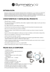
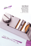
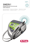
User Manual • Benutzerhandbuch • Manuel de l’utilisateur • Manuale per l’utente
Manual del Usuario • Manual do Usuário •
_
TECHNICAL DATA (SPECIFICATION)
INTRODUCTION
Model
Symmetry IQ® 4000 Series
Classification EN 60601-1
Class I device
Classification 93/42 EEC
Class IIa
Mode of Operation
Continuous operation
Power Source
AC120V +/- 10% 50/60Hz
AC230V +/-10% 50/60Hz
Power Consumption
42VA
• Compact, lightweight device.
Water Pressure
0.1 - 0.5MPa (15-73 psi)
• Three color-coded selectable and adjustable pre-defined power modes for a variety of dental procedures.
Ultrasonic Specifications
Maximum output:
Frequency range:
8 Watts
28-32kHz
Lighting
Yes
• Fiber-optic handpiece to enhance visibility.
Dimensions in mm (WxDxH)
203mm x 255mm x 85mm (8in x 10in x 3.4in)
• Lightweight, large diameter handpiece encourages a light grasp to reduce operator fatigue.
Weight
2.5kg (Control Unit) (5.5 lbs)
• Soft, textured silicone finger grip for clinical comfort and control.
Length of Handpiece Cord
2.0m Max
• Autoclavable handpiece for infection control.
Length of Foot Control Cord
2.5m Max
Fuses
120V:T1.25AL/125V,230V:T400mAL/250V
Bottle Volume
350mL/500mL (11.8 oz /16.9 oz)
Degree of p rotection against ingress of water as
detailed in the current edition of IEC 60529
Unit: Ordinary
Foot Control: IPX1
Operating Conditions
0-40 C (32 - 104 F)
10-85% relative humidity
500-1060hPa atmospheric pressure (7 - 15 psi)
Storage and Transport Conditions
-10-60 C (14 - 140 F)
10-85% relative humidity
500-1060hPa atmospheric pressure (7 - 15 psi)
Thank you for purchasing the Symmetry IQ product. This product is intended to be operated by dental
professionals only. This device generates ultrasonic vibrations intended for use in dental applications such
as scaling, periodontal therapy, root canal treatment and cavity preparation. Read this operation manual
carefully before use and retain for reference. This device does not require special training.
PRODUCT FEATURES AND BENEFITS
• Easy to read digital display for trouble-free operation.
• Convenient memory feature to store frequently used operational settings.
• Durable, lightweight handpiece cord.
• Two methods of irrigation are available (dental unit/city water and irrigation bottle). The selection of no
irrigation is also an option.
• Irrigation tube is isolated within the control unit to prevent solution from coming in contact with the
electronics of the unit.
• Two irrigation bottles for use with the IQ 4000 unit.
• Easy to clean design to minimize the risk of cross-contamination.
COMPONENT PARTS
1.
2.
3.
4.
5.
6.
7.
8.
9.
10.
11.
12.
13.
14.
Control Unit
Symmetry IQ Handpiece
Replacement Bulb
Water Tube
Symmetry IQ Fiber-optic Handpiece Cord
Spanner Wrench (5X8) – 2 pieces
Foot Control
AC Power Cord
Irrigation Connector (AC 120V Only)
Irrigation Bottles – 2 pieces
O-rings for irrigation bottles (not pictured)
Tip Wear Guide (not pictured)
Power Range Guide (not pictured)
Three Symmetry S-Series Tips (not pictured)
3
SYMBOLS AND GENERAL SAFETY
WARNING
Risk of damage or harm
Type BF applied part
Attention, consult accompanying documents
Sterilizable up to 135˚C
CE marking: Refers to directive 93/42 EEC,
including IN 60601-1 and EN 60601-1-2
City Water
Authorized representative in the European
community.
Irrigation Bottle
• To avoid electrical shock, do not plug or unplug the power cord with wet hands.
• To minimize risk of short circuit and electric shock; prevent water from contacting the control unit.
• Subjecting handpiece to a strong impact or drop onto a hard surface could result in electric shock.
C
US
• Use a power cord that has a grounding prong to prevent electric shock.
• Do not disassemble or alter the handpiece.
• Keep away from explosive substances and flammable materials.
• Do not use this product in the presence of inflammable anesthetics or gases.
• Confirm water is flowing adequately from the tip. Insufficient water flow to the tip could result in excess
heat to the tip, leading to hard and soft tissue damage or overheating of the handpiece.
Dispose of this device and its accessories via
methods approved for electronic devices and
in compliance with the Directive 2002/96/CE
Foot Control
Equipment or Equipment parts can transmit RF
electromagnetic energy.
Power Plug
TUV Rhineland of North America is a Nationally
Recognized Testing Laboratory (NRTL) in the
United States and is accredited by the Standards
Council of Canada to certify electro-medical
products with Canadian National Standards.
This Way Up
Protected against vertically falling water drops.
Handle With Care
• Contraindication: ultrasonics may interfere with proper function of cardiac pacemakers. This device is
not recommended for use on patients with cardiac pacemakers.
• Use recommended fuse: 120V:T1.25AL/125V, 230V: T400mAL/250V.
• This product needs special precautions regarding EMC and needs to be installed and put into service
according to the EMC information.
• Portable and mobile RF communications equipment can affect this product.
Keep Dry
CAUTIONS FOR HANDLING AND OPERATION
Read these instructions carefully and use only as intended or instructed. Safety instructions are intended to
avoid potential hazards that could result in personal injury or damage to the device.
DEGREE OF RISK
WARNING
A hazard that could result in bodily injury or damage to the device if safety
instructions are not followed.
CAUTION
A hazard that could result in light or moderate bodily injury or damage to the
device if the safety instructions are not followed.
NOTICE
• Touching the back end of the handpiece, where electrical connections are attached to the cord may
result in electric shock.
General information needed to operate the device safely.
• The use of ACCESSORIES, transducer and cables other than those specified, with the exception of
transducers and cables sold by the manufacturer of the product as replacement parts for internal
components, may result in increased EMISSIONS or decreased IMMUNITY of it.
• This product should not be used adjacent to or stacked with other equipment and that if adjacent or
stacked use is necessary, it should be observed to verify normal operation in the configuration in which
it will be used.
5
CAUTION
• The handpiece is designed for clinical dental use only.
• Always consider the safety of the patient when operating the handpiece.
• Applied part is BF type.
• Check tip vibration outside the oral cavity before use. If any irregularities are found, discontinue use
immediately and contact your dealer.
• Do not force or pull on the power cord and/or handpiece cord. It could cause disconnection.
GUIDANCE AND MANUFACTURER’S DECLARATION –
ELECTROMAGNETIC IMMUNITY
The Symmetry IQ 4000 Series is intended for use in the electromagnetic environment specified below. The customer
or the user of the Symmetry IQ 4000 Series should assure that it is used in such an environment.
Immunity Test
IEC60601 test level
Compliance level
Electromagnetic environmentguidance
Electrostatic discharge
(ESD) IEC61000-4-2
±6kV contact
±8kV air
±6kV contact
±8kV air
Floors should be wood,
concrete or ceramic tile.
If floors are covered with
synthetic material, the relative
humidity should be at least
30%.
Electrical fast
transient/burst
IEC61000-4-4
±2kV for power
supply lines
±1kV for input/output
±2kV for power
supply lines
±1kV for input/output
Mains power quality should be
that of a typical commercial or
hospital environment.
Surge
IEC61000-4-5
±1kV line(s) to line(s)
±2kV line(s) to earth
±1kV line(s) to line(s)
±2kV line(s) to earth
Mains power quality should be
that of a typical commercial or
hospital environment.
Voltage dips, short
interruptions and
voltage variations on
power supply input
lines
IEC61000-4-11
<5% Ut
(>95% dip in Ut)
for 0.5 cycle
<5% Ut
(>95% dip in Ut)
for 0.5 cycle
40% Ut
(60% dip in Ut)
for 5 cycles
40% Ut
(60% dip in Ut)
for 5 cycles
70% Ut
(30% dip in Ut)
for 25 cycles
70% Ut
(30% dip in Ut)
for 25 cycles
<5% Ut
(>95% dip in Ut)
for 5 sec
<5% Ut
(>95% dip in Ut)
for 0.5 cycle
<5% Ut
(>95% dip in Ut)
for 0.5 cycle
40% Ut
(60% dip in Ut)
for 5 cycles
40% Ut
(60% dip in Ut)
for 5 cycles
70% Ut
(30% dip in Ut)
for 25 cycles
70% Ut
(30% dip in Ut)
for 25 cycles
<5% Ut
(>95% dip in Ut)
for 5 sec
Mains power quality should be
that of a typical commercial
or hospital environment. If
the user of the Symmetry
IQ 4000 Series requires
continued operation during
power mains interruptions,
it is recommended that
the Symmetry IQ 4000
Series be powered from an
uninterruptible power supply
or a battery.
Power frequency
(50/60Hz)
magnetic field
IEC61000-4-8
3 A/m
3 A/m
Power frequency magnetic
fields should be at levels characteristic of a typical location in
a typical commercial or hospital
environment.
• Do not exceed recommended power ranges for the tips. Excess power may damage tooth structure
and/or result in damage to or excess wear of the tip.
• Check the tip before every use. Tips that have been bent, altered, worn or compromised in any way
should be removed from service.
• Do not use tips on metal or ceramic restorations, unless tips are intended specifically for this purpose.
• Do not bend, alter or modify tips. Damage may occur to the tips affecting ultrasonic vibration.
• To eliminate risk of damage to the soft and hard tissues keep the tip moving at all times when in contact
with the tooth, gingiva, mucosa and intra-oral tissues.
• Confirm the threaded area of the tip is clean of all debris.
• To ensure proper tip vibration attach the tip securely to the handpiece with the Guardian wrench and
tip carrier. See figure 11.
• Attach the handpiece before turning on the power.
• Do not drop or otherwise expose the control unit to excess trauma.
• Use Hu-Friedy® Symmetry S-Series tips to ensure proper performance.
• Do not thermo-disinfect or autoclave any parts unless indicated so in the User Manual.
• Sterilization by ultraviolet light may cause discoloration of the handpiece.
• If water is spilled on the irrigating pump cover, wipe thoroughly and allow it to dry completely prior to
use. If water gets inside the irrigating pump the rollers may slip and fail to pump irrigation solution.
• The system functions normally when the temperature is at 0˚-40˚C (32˚-104˚ F), relative humidity at
10-85% RH, atmospheric pressure at 500-1060hPa and no moisture condensation occurs in the unit.
Use outside of these conditions may cause malfunction.
NOTICE
• During vibration, the handpiece and the handpiece cord may affect computer and LAN cable. Noise
may be heard during operation near a radio receiver.
• Turn off the power switch after use. Remove the power plug and the water inside the control unit if not
used for an extended period of time.
•Applied parts for patient and/or operator are tip and handpiece.
• Users are responsible for operation control, maintenance and inspection.
• Store at -10˚-60˚C (14˚-140˚F), relative humidity at 10-85%RH, atmospheric pressure at 500-1060hPa.
Do not subject system to dust, sulfur or salinity.
• Contact dealer or Hu-Friedy Mfg. Co., LLC if problems occur.
NOTE: Ut is the a.c. mains voltage prior to application of the test level.
7
GUIDANCE AND MANUFACTURER’S DECLARATION –
ELECTROMAGNETIC IMMUNITY
GUIDANCE AND MANUFACTURER’S DECLARATION –
ELECTROMAGNETIC IMMUNITY
The Symmetry IQ 4000 Series is intended for use in the electromagnetic environment specified below. The customer
or the user of the Symmetry IQ 4000 Series should assure that it is used in such an environment.
The Symmetry IQ 4000 Series is intended for use in the electromagnetic environment specified below. The customer
or the user of the Symmetry IQ 4000 Series should assure that it is used in such an environment.
Immunity Test
Cables and accessories Maximum length
Shield
Complies with
Handpiece cord
2.0 m
Unshielded
RF emissions, CISPR11
Foot Controler
2.5 m
Unshielded
Harmonic emissions
IEC61000-3-2
Voltage fluctuations/ flicker emission
IEC61000-3-3
Electrostatic discharge (ESD)
IEC61000-4-2
Electric fast transient / burst
IEC61000-4-4
IEC60601
test level
Compliance
level
Electromagnetic environment - guidance
Portable and mobile RF communications equipment should be
used no closer to any part of the Symmetry IQ 4000 Series,
including cables, than the recommended separation distance
calculated from the equation applicable to the frequency of the
transmitter. Recommended separation distance:
Conducted RF
IEC61000-4-6
Radiated RF
IEC61000-4-3
3Vrms
150 kHz to
80MHz
3V/m
80MHz to 2.5
GHz
3 Vrms
3 V/m
—
d = 1.2 √ P
Class B/ Group 1
Surge
Voltage dips, short interruptions and
voltage variations on power supply
input lines
—
d = 1.2 √ P 80MHz to 800MHz
—
d = 2.3 √ P 800MHz to 2.5GHz
Where P is the maximum output power rating of the transmitter
in watts (W) according to the transmitter manufacturer and
d is the recommended separation distance in metres (m).
Field strengths from fixed RF transmitters as determined by an
electromagnetic site survey, should be less than the compliance
level in each frequency range. Interference may occur in the
vicinity of equipment marked with the following symbol:
NOTE 1: At 80MHz and 800MHz, the higher frequency range applies.
NOTE 2: These guidelines may not apply in all situations. Electromagnetic propagation is affected by absorption and
reflection from structures and objects.
NOTE 3: Use of handpiece, cable and other components that are not manufactured or offered by the Manufacturer
of the unit may affect Symmetry IQ 4000 EMC performance. Symmetry IQ 4000 should not be used adjacent to
or stacked with other equipment. If this is necessary, confirm that Symmetry IQ 4000 Series and other equipment
function as expected.
a. Field strengths from fixed transmitters, such as base stations for radio (cellular/cordless) telephones and land
mobiles radios, amateur radio, AM and FM radio broadcast and TV broadcast cannot be predicted theoretically with
accuracy. To assess the electromagnetic environment due to fixed RF transmitters, an electromagnetic site survey
should be considered. If the measured field strength in the location in which the SYMMETRY IQ 4000 SERIES is used
exceeds the applicable RF compliance level above, the SYMMETRY IQ 4000 SERIES should be observed to verify
normal operation. If abnormal performance is observed, additional measures may be necessary, such as reorienting or
relocating the SYMMETRY IQ 4000 SERIES.
b. Over the frequency range 150kHz to 80MHz, field strengths should be less than 3 V/m.
IEC61000-4-5
IEC61000-4-11
Power frequency(50/60Hz)
magnetic field
IEC61000-4-8
Conducted RF
IEC61000-4-6
Radiated RF
IEC61000-4-3
GUIDANCE AND MANUFACTURER’S DECLARATION –
ELECTROMAGNETIC IMMUNITY
The Symmetry IQ 4000 Series is intended for use in the electromagnetic environment specified below. The customer
or the user of the Symmetry IQ 4000 Series should assure that it is used in such an environment.
Emissions test
Compliance
Electromagnetic environment - Guidance
RF emissions CISPR11
Group 1
The Symmetry IQ 4000 Series uses RF energy only for
its internal function. Therefore, its RF emissions are very
low and are not likely to cause any interference in nearby
electronic equipment.
RF emissions
CISPR11
Class B
Harmonic emissions
IEC61000-3-2
Class A
Voltage fluctuations/
flicker emissions
IEC61000-3-3
Complies
The Symmetry IQ 4000 Series is suitable for use in
all establishments, including domestic establishments
and those directly connected to the public low-voltage
power supply network that supplies buildings used for
domestic purposes.
9
RECOMMENDED SEPARATION DISTANCES BETWEEN
PORTABLE AND MOBILE RF COMMUNICATIONS EQUIPMENT
AND THE SYMMETRY IQ 4000 SERIES
The Symmetry IQ 4000 Series is intended for use in an electromagnetic environment in which radiated RF
disturbances are controlled. The customer or the user of the SYMMETRY IQ 4000 SERIES can help prevent
electromagnetic interference by maintaining a minimum distance between portable and mobile RF communications
equipment (transmitters) and the Symmetry IQ 4000 Series as recommended below, according to the maximum
output power of the communications equipment.
Rated maximum output power
of transmitter
W
Separation distance according to frequency of transmitter
m
150kHz to
80MHz
d = 1.2 √P
80MHz to
800MHz
d = 1.2 √P
800MHz to 2.5GHz
d = 2.3 √P
0.01
0.12
0.12
0.23
0.1
0.38
0.38
0.73
1
1.2
1.2
2.3
10
3.8
3.8
7.3
100
12
12
23
For transmitters rated at a maximum output power not listed above, the recommended separation distance in
meters (m) can be estimated using the equation applicable to the frequency of the transmitter, where P is the
maximum output power rating of the transmitter in watts (W) according to the transmitter manufacturer.
NOTE 1: At 80 MHz and 800 MHz, the separation distance for the higher frequency range applies.
NOTE 2: These guidelines may not apply in all situations. Electromagnetic propagation is affected by absorption and
reflection from structures, objects and people.
INSTALLATION AND ASSEMBLY
1. UNPACKING THE DEVICE
Upon receipt please check device for any damage caused in transit. If necessary, contact your dealer.
2. GENERAL RECOMMENDATIONS
Connect the Symmetry IQ 4000 control unit to electric supply in accordance with current standards.
The water supply system should be of adequate quality for the practice of dental treatment. Additionally, the
city water supply should be equipped with a cut-off system.
3. WATER SYSTEM SETUP
Use of City Water
Remove the cover from the water connector (Fig. 1)
Connect the filter side of the water tube by inserting deep into the
water connector on the Symmetry IQ control unit. (Fig. 2)
Connect the provided water tube to the water outlet on the dental unit.
To remove the water tube from the control unit, push the white ring
(the quick connector release ring) and gently remove the tube. (Fig. 3)
When the water tube is not connected, place the cover on the water
tube connector on the control unit.
CAUTION: Be sure to insert the water tube deep into the
connector on the control unit. If water has not been used recently
at the water outlet of the dental unit, discolored water may come
out. Wait until the water coming out of the dental unit is clean
before connecting to the control unit.
Use of Irrigation Bottle
Remove the dust cover from the base unit. (Fig. 4)
Remove the cap of the irrigation bottle and fill solution to the
desired level.
Close the cap of the irrigation bottle, check the air hole to confirm
it is clean and insert the bottle into the connector located on the unit.
(Fig. 5) When attached properly, the irrigation bottle will click into place.
To remove the irrigation bottle, pull the bottle straight up.
Gradation lines are printed on both sides of the irrigation bottle and
can be read accurately from the fill position or when mounted on the
control unit.
Mount the dust cover on the base unit when irrigation bottle is not
in use.
NOTICE: Please make sure the connector and surrounding area
is completely clean before installing the irrigation bottle. Wipe the
irrigation bottle and connector area thoroughly prior to inserting
the irrigation bottle.
11
OPERATING PROCEDURES
4. FOOT CONTROL CONNECTION
Connect the foot control plug to the foot control connector at the back
of the control unit. (Fig. 6)
1. WATER SYSTEM SETUP
Align the marks on the foot control cord and on cowl located on the
back of the unit. Take care to properly align all the pins. Push the plug
gently into the connector.
Use of City Water
Carefully check all water supply connections prior to start-up. Open the dental unit’s water valve.
Set water pressure between 0.1-0.5MPa (15-73 psi).
Use of Irrigation Bottle
Confirm that the irrigation bottle is filled to the appropriate level.
5. POWER CORD CONNECTION
Insert the power cord into the inlet at the back of the control unit.
(Fig. 7) Plug the power cord into the power receptacle.
If water or other liquids are spilled on the irrigation pump, please wipe it off thoroughly and allow to dry
completely prior to use. If water gets inside the irrigation pump the roller may slip and fail to pump irrigation.
6. HANDPIECE CORD CONNECTION
Align the marks on the control unit and the handpiece cord plug.
Gently push the plug into the connector at the front of the control
unit. (Fig. 8)
Do not put highly acidic liquids in the irrigation bottle. A list of approved liquids is available upon request
or you can visit Hu-Friedy.com.
2. TIP CONNECTION
Your Hu-Friedy Symmetry S-Series piezo tip comes with its own tip
carrier/torque limiting wrench (the Guardian™ wrench, Fig. 10).
7. HANDPIECE CONNECTION
Confirm there is no moisture in the handpiece connector. If moisture is
present, dry it with cloth or air syringe.
Attach tip to handpiece using the Guardian wrench by aligning the
threaded end of the tip to the handpiece. (Fig. 11)
Align the marks on the handpiece with the marks on the handpiece
hose to properly align the electrical contacts. (Fig. 9) Gently push straight
to connect. Do not twist handpiece connector to connect.
Rotate the Guardian wrench clockwise.
Complete installation of the tip by rotating the Guardian wrench
until you hear clicking.
Place the handpiece in the handpiece holder on the control unit.
To remove handpiece from the handpiece cord, first remove tip, then
firmly grip the front section of the handpiece in one hand and the rear
section of the handpiece cord plug with the other hand and pull to
separate. Do not twist to separate.
10
WARNING: Do not touch the back end of the handpiece
(where electrical connections are made to the cord). It may
result in electric shock.
3. TIP REMOVAL
Hold the handpiece vertically. Insert the tip through the hole in the bottom of the Guardian wrench.
Depress wrench slightly while rotating to fully secure tip to wrench.
CAUTION:
1. D
o not disconnect the cord handpiece when power to the
device is switched on and the footswitch is depressed.
2. Detach tip before removing handpiece.
3. Push handpiece against handpiece cord plug to connect.
4. Grip the plug of the handpiece cord when removing handpiece.
Turn the Guardian wrench counter-clockwise to loosen and remove tip from handpiece.
Once removed from handpiece, do not remove the tip from the Guardian carrier.
CAUTION: Proper vibration of a tip depends on correct attachment to the handpiece. Always use the
torque-limiting Guardian wrench to ensure proper tip attachment and to eliminate over tightening or
inadequate attachment of the tip. Over tightening of the tip may result in damage of the handpiece or tip.
8.START-UP
The following procedures are recommended before using your Symmetry IQ 4000 for the first time:
• Clean and sterilize all appropriate accessories.
• After installation of the device, operate the device at the lowest power setting while applying pressure to
the foot control. This procedure will confirm adequate water flow and rinse the internal water circuits.
• Disconnect the handpiece and proceed with recommended cleaning and sterilization procedures.
(See pages 13–14, Cleaning & Sterilization)
When using the Guardian wrench without a tip previously inserted
into the tip carrier, take the following step: place the Guardian wrench
over the tip by slipping tip through the small hole in the bottom, closed
end of the tool. This will position the tip within the Guardian wrench for
safety and convenience.
4. POWER ON
Connect the power cord to the wall outlet. Turn on the power switch
on the control unit. (Fig. 12) Front panel will light up.
CAUTION: Use of any wall outlets other than those of
AC120V +/- 10% or AC230V +/- 10% may result in damage
to the power cord.
13
5. OPERATION MODE SELECTION
Select the appropriate mode for procedure with the mode selection keys on the front
panel. The light below the selected mode will illuminate.
9. WHEN TREATMENT IS COMPLETED
• Release the foot control and replace the handpiece in the handpiece
holder. (Fig. 15)
ORANGE
• Turn off the power switch.
BLUE
NOTICE: Color of the Guardian (torque limiting wrench/tip carrier) indicates the
primary application mode on the Symmetry IQ 4000 unit. Please use as follows:
• Select ORANGE Mode for Symmetry tips with an ORANGE Guardian wrench
• Select BLUE Mode for Symmetry tips with a BLUE Guardian wrench
• Select GREEN Mode for Symmetry tips with a GREEN Guardian wrench.
Pre-select the appropriate power setting prior to patient treatment. See recommended
power setting guide included with your Symmetry IQ Unit. Note that certain tips may
be used in two power modes. Please adjust accordingly.
• If using city water
GREEN
• Remove the Symmetry tip with the Guardian Tip Carrier/Wrench.
CAUTION: When using alternative solutions, always clean the entire irrigation system thoroughly
(See page 10, Auto Cleaning).
6. WATER MODE SELECTION
Dry
POWER
Push the water key on the control panel to select option for water flow.
Three water modes are available on the front panel of the Symmetry IQ
4000. Dry mode, Irrigation Bottle, or City Water (Fig 13). The light on the
control panel will illuminate when water option is selected.
NOTICE: When the unit is shut down, the last mode settings in use are automatically retained in
memory. When you power up the control unit for the next procedure the system will reactivate in the
same configuration as when shut down.
W
SAFETY FUNCTION
When the operation mode is set to ORANGE Mode and the power setting is set to Max the unit will
automatically reduce power if operated at these settings for more than 10 minutes. (The output display
reduces 3 lights from “Max” to “8”)
WARNING: Always use water supply. Insufficient water supply
M will cause excessive heat which may
result in damage to the tooth or other intra-oral tissues and possibly cause the tip to break. Dry mode
should only be used when water would be detrimental to the dental procedure being performed, and
should only be used for a few seconds at a time.
To reset the safety function:
• Before a lapse of 10 minutes or when the power weakens after a lapse of 10 minutes, release the foot
control. The safety feature is now reset. To use at Max power again, adjust power level using the power key.
7. POWER RANGE SETTING
WARNING: Do not exceed recommended power range indicated on the Symmetry Power Range
Guide. Higher than recommended power may damage tooth structure and/or tip.
Set the recommended power level with the power
key on the front panel. The light in the power
display panel will indicate the selected power level.
Confirm that power level is set in the appropriate
range for the selected Symmetry tip.
MODE
1
2
3
4
, close the dental unit’s water valve.
, thoroughly wash the irrigation bottle
• If using irrigation bottle
water supply system. Please refer to page 14–15, Maintenance of the
Control Unit: Auto Cleaning – Cleaning of Irrigation Tube.
5
6
7
8
• Depressing the foot control repeats the same operation.
9
10
If the power switch to the control unit is turned on while the foot control is depressed accidentally, the
control unit will beep to alert user.
ORANGE
PRESET MEMORY FUNCTION
The control unit can be preset for water mode, power setting and operating mode. To set the desired
preset conditions into memory follow the procedure below:
POWER
BLUE
GREEN
NOTICE:
• Continuous pushing of the power level key will cause the power level to increase.
• When water only is desired without oscillation of the tip, push the power level key to extinguish the
power level display. Water will flow, but the handpiece ring light will not illuminate.
• To ensure patient comfort and to extend the life of your tips always use the lowest effective power setting.
8. FOR OPERATION
• Verify that the water supply is adequate and clean prior to beginning
each procedure.
• Adjust the power level to the recommended range.
• Push and hold the memory button
for at least 2 seconds. The memory light will illuminate and the
control unit will beep. The settings are now in memory.
• T
o enter new settings: After confirming the water mode, power mode and operating mode, push and
hold the Memory key for approximately 2 seconds. The Memory light will illuminate. The old memory is
cleared and the new settings are programmed.
• To operate at the Memory settings, press the memory button
MAX
once.
MIN
CLEANING AND STERILIZATION
• Depress the foot control to start tip vibration. The fiber-optic light
will illuminate.
• Turn the water adjustment knob counterclockwise gradually to increase
water flow. Use the blue colored knob to adjust water from city water
connection and the green colored knob to adjust water flow from irrigation bottle.
• Set the desired levels. (operation mode, water mode and power setting)
(Fig. 14)
Clean and sterilize prior to first use and after each patient as noted below. Autoclave sterilization is
required for handpiece and replacement tips prior to first use and after each patient. Do not sterilize by
ultraviolet light. Cover the control unit with a barrier or wipe clean with a pH neutral surface disinfectant. The
following cleaning and/or sterilization procedures are recommended for the control unit, foot control
or handpiece cord.
15
CAUTION: Do not sterilize the control unit, power cord, foot control, water tube, irrigation connector,
irrigation bottle, handpiece cord including the cover, lamp, o-ring, tip card or spanner wrenches.
PROCEDURES FOR THE SYMMETRY UNIT
1. Turn off the power switch.
2. Remove the tip from the handpiece using the Guardian Tip Carrier/Wrench. (See Fig. 11)
3. Remove the handpiece from the handpiece cord as described in Installation and Assembly:
Handpiece Connection.
4. After each use please remove all the disinfectant solution and perform “Auto Cleaning” or “Manual
Cleaning” procedure. See pages 14–15. Cleaning the irrigation tube after each use will eliminate chemical build up in the tubing and on metal parts. Metal parts may rust if chemicals are not removed at each use.
5. Wipe the control unit, foot control or handpiece cord with a clean cloth dampened with a surface
disinfectant. Do not spray disinfectant solution directly on the control unit.
6. The use of an abrasive wipe or cleaning solution will damage the surface finish of the control unit.
PROCEDURES FOR THE SYMMETRY HANDPIECE
1. Clean the outer surface of the handpiece by wiping with a soft cloth dampened with pH neutral
surface disinfection solution (not containing phenols). Do not spray the cleaning solution directly
on the handpiece.
2. Wipe debris off the end of the optic fibers at the handpiece with an alcohol soaked cotton swab.
3. Place the handpiece in a cassette or sterilization pouch and seal.
4. Autoclave the handpiece for 15 minutes at 273˚F/134˚C.
PROCEDURES FOR SYMMETRY PIEZO TIPS
1. Clean, disinfect, inspect and steam sterilize before each use.
2. Tips remain in the Guardian wrench during the complete cleaning, disinfection and sterilization
reprocessing cycle.
3. Clean piezo tips using ultrasonic cleaner or thermo disinfector.
4. Steam sterilize for at least 20 minutes at 250˚F/121˚C, or 5 minutes at 273˚F/134˚C.
5. Do not heat above 350˚F/177˚C.
6. Do not expose to phenols, iodophors or dry heat sterilization.*
* Detailed care and maintenance instructions are available upon request or go to Hu-Friedy.com.
CAUTION: Do not place the handpiece on the bottom shelf of the sterilizer. To prevent exposure to
excess heat, place handpiece and tips on the middle and top shelves of the sterilizer.
MAINTENANCE OF THE CONTROL UNIT
AUTO CLEANING – CLEANING OF IRRIGATION TUBE
(Use of Irrigation Bottle )
CAUTION: After each use please remove all the alternative solution and perform “Auto Cleaning”
procedure. Cleaning the irrigation tube after each use will eliminate chemical build up in the tubing
and on metal parts. Metal parts may rust if chemicals are not removed at each use.
1. Pull straight up on the irrigation bottle to remove the bottle from
the control unit.
16
2. Fill a spare bottle with at least 175ml with clear distilled water.
3. Place the cap on the bottle, check the irrigating bottle connector
opening and surrounding area of the control unit and clean as
necessary. After cleaning, install the irrigation bottle by pressing
down until it clicks into place. (Fig. 16)
CAUTION: Use only distilled water for cleaning and confirm the
connector hole and surrounding area is clean and free of debris.
4. Turn the irrigation bottle adjustment knob (green) to maximum
water flow. (Fig. 17)
17
MAX
MIN
5. Select the Irrigation Bottle water selection mode on the display panel.
The Irrigation Bottle lamp will illuminate. (Fig. 18)
6. Press and hold the water selection mode key for 2 seconds. The unit
will beep, all the lamps except the irrigation bottle lamp will
shut off
POWER
and the auto cleaning sequence will begin. The auto cleaning sequence
takes approximately 30 seconds.
7. After the auto cleaning commences sequence pushing the water
selection mode key will stop the sequence.
Dry
W
18
CAUTION: If you press the mode selection key or the power key during the auto cleaning sequence,
M not exceed the maximum recommended
the tip will vibrate. Please confirm the power setting does
power for the tip.
NOTICE: Setting the irrigation bottle water adjustment knob at less than maximum during auto cleaning
will result in incomplete cleaning in the 30-second cycle.
8. When the auto-cleaning sequence completes, the unit will revert to the settings prior to cleaning.
9. Remove the irrigation bottle by pulling straight up.
10. After use please thoroughly clean and dry all bottles prior to next use.
MANUAL CLEANING METHOD – CLEANING OF IRRIGATION TUBE (Use of Irrigation Bottle)
1. Pull straight up on the irrigation bottle to remove it from the control unit.
2. Open the cap of the irrigation bottle, remove any remaining solution and fill the bottle with distilled water.
3. Close the cap firmly and replace the bottle on the control unit. (Make sure the air hole is clean and free
from debris). Insert the bottle into the irrigation connector opening; push down until it clicks.
4. Operate the unit for approximately 30 seconds with irrigation bottle water flow at maximum setting.
WATER LINE MAINTENANCE
Local, regional and federal authorities establish safe potable water quality level guidelines for human use. In
Europe the maximum accepted level of colony forming units of bacteria (cfu’s) for potable water used in
DUWLs is no more than 100 cfu/ml at a temperature of 22°C (20 cfu/ml at a temperature of 36°C). In the
U.S., the Centers for Disease Control established a 500 cfu/ml level, while the American Dental Association
sets a maximum level of 200 cfu/ml. Follow regulatory recommendations in your region regarding flushing
dental unit water lines.
17
CHANGING WATER FILTER
Close the water valve of the dental unit to which the Symmetry IQ
4000 control unit is connected. Mount two (5X8) spanner wrenches
as shown in Fig. 19 and turn in the directions shown. This motion may
cause the water tube to become twisted. If this occurs, relieve the
twist by turning the tube at the end on the control unit so the side is
free to turn.
CLEANING FIBER-OPTIC LIGHT
Wipe debris off the end of the optic fibers at the handpiece with an alcohol soaked cotton swab. (Fig. 26)
5
19
When the water filter case is separated, the water filter can be
removed as shown in Fig. 20. Replace filter and reassemble the filter
in the reverse order. Optional Water Filter: Order No. UPWF.
CAUTION: Be sure to replace the water filter in the proper
direction. The side of the filter with the o-ring should be pointed
towards the control unit side. If assembled in the wrong direction
the effect of the water filter will be lost.
CHANGING THE O-RING ON THE IRRIGATION BOTTLE
Remove two O-rings at the bottle joint with a pointed instrument,
and place new ones into the grooves. (Fig. 21) Optional O-ring : Order
No. UP4ORINGS
CHANGING FIBER-OPTIC LIGHT
Disassemble the handpiece from the handpiece cord.
(See Installation & Assembly)
6
20
CAUTION: Do not use any sharp pointed tools to clean the optic fiber end face. In case the light
becomes dim, contact your dealer.
Remove the handpiece sleeve. Use a small screw driver to push the lamp
out. (Fig. 27)
Align the lamp pins of the new lamp with the holes and push the lamp
into place.
Align the mark on the handpiece sleeve with the same mark on the
handpiece cord. Push the sleeve to the cord until it clicks. (Fig. 28)
CAUTION: Do not touch glass part of new lamp and exercise care when mounting a new lamp to
avoid dislodging the o-ring from the groove.
21
CHANGING THE IRRIGATION PUMP (Use of Irrigation Bottle)
Remove the irrigation bottle by pulling straight up.
Remove the irrigation pump cover by gently pulling up on the cover.
(Fig. 22)
Push the coupling in to release the tube connector and disconnect
the irrigation tube. (Fig. 23)
22
Remove the irrigation tube from connector. (Fig. 24)
WARNING: Do not use the device if it appears to be defective.
Turn the irrigation pump counterclockwise until it clicks. Pull out pump.
Align the replacement irrigation pump with the drive shaft at the same
position and turn clockwise until it clicks. (Fig. 25 )
NOTE: If a failure occurs, contact the supplier of your
Symmetry IQ product. Repair by unauthorized person may
void warranty.
Connect the irrigation tube to the connector.
Insert the tube connector to the coupling until it clicks.
Optional Irrigation Pump : Order No. UP4PUMP
23
When reinstalling the pump cover be sure to tuck in irrigation tubing
to prevent pinching of the water tubing.
CAUTION: Before replacing the irrigation pump, wipe off excess
water on pump and drive shaft. The wet drive shaft and rollers can
be slippery and cause improper operation.
Replacement Fuse: T1.25AL/125V (120V) Order No. UP4FUSE120,
T400mAL/250V (230V) Order No. UPFUSE230
24
• To prevent damage to the pump rollers, use a gentle pushing
motion to insert the replacement irrigation pump onto the drive
shaft. Do not twist.
• Run the replaced irrigation pump about 10 seconds on highest
water volume setting before operation to adopt irrigation tube
to new pump.
REPLACING THE FUSE
Depress the spring tabs located on the top and bottom of the
power connector assembly and remove it to change the fuses.
(Fig. 29)
25
WARNING: Use a fuse with the following specified rating.
(120V : T1.25AL/125V, 230V : T400mAL/250V)
4
19
SERVICE
TROUBLESHOOTING
Please send your Symmetry IQ 4000 to your dealer or an authorized Hu-Friedy repair center. Shipping your
product in its original packaging will offer the best protection against damage during shipping. If sending
directly to an authorized Hu-Friedy repair center, please include the name and address of your dealer. All
items must be cleaned, disinfected and sterilized as described in the operating instructions before shipment.
DISPOSAL AND RECYCLING
Dispose of this device and its accessories via methods approved for electronic devices and in compliance
with the Directive 2002/96/CE. At the end of their life, tips should be discarded in safety containers designed
for this purpose.
PROBLEM
Control lamp does not
illuminate when the unit
is switched on.
No/poor ultrasonic
vibration and handpiece
is leaking.
EU REGULATORY INFORMATION
When drawing water directly from a dental chair or other water supply system within a dental practice for
the Symmetry IQ 4000, a system or device must be installed to ensure that no contaminated water can
flow or be sucked back into the drinking water supply. When installing such a system please observe that the
requirements of the EN1717 Regulations are adhered to.
The tip is bent or broken.
CAUSE
The power cord or the jack is
disconnected
Check the power supply to the dental office.
The internal fuse has burned out.
Contact your dealer or Hu-Friedy.
The tip is not tightened firmly.
Tighten the tip with the Guardian wrench until you hear
a click.
The tip is worn.
Replace the tip.
Power has not been properly
adjusted for the tip.
Adjust the power setting to the
recommended power range indicated
on the Guardian wrench package insert.
The foot control is disconnected.
Connect the foot control correctly.
Handpiece failure.
Contact your dealer or Hu-Friedy.
Using E-Series Tips.
Check tip part code.
Foot control failure.
Contact your dealer or Hu-Friedy.
Excess power to the tip.
Operate the tip only in the recommended
power range indicated on the Guardian wrench
or Power Range guide.
Tip was dropped or mishandled
during cleaning and sterilization.
Always process the tip in the Guardian wrench.
HELPFUL INFORMATION
The use of higher than recommended power setting may cause excessive wear or tip breakage.
SOLUTION
Check all the connections of the control unit.
Discard bent or broken tips.
Always remember to properly tighten the tip to handpiece using the Guardian wrench.
The tip unthreads itself.
The tip is not tightened properly.
Scaling efficiency can diminish significantly with worn tips. Inferior performance and poor water delivery can
result from worn, damaged, bent or altered tips. For optimal scaling efficiency, we recommend checking tips
regularly for signs of wear.
Tighten the tip with the Guardian wrench until you
hear a click.
Noise from the
handpiece.
Output has not been properly
adjusted for the tip.
Adjust the power setting to the
recommended power range indicated
on the Guardian wrench or package insert.
The tip is not tightened firmly.
Tighten the tip with the Guardian wrench until you
hear a click.
Vibration failure in the
handpiece or the control unit.
Contact your dealer or Hu-Friedy.
Output has not been properly
adjusted for the tip.
Adjust the power setting to the
recommended power range indicated
on the Guardian wrench or package insert.
The tip is not tightened properly.
Tighten the tip with the Guardian wrench until you
hear a click.
Vibration failure in the handpiece
or the control unit.
Contact your dealer or Hu-Friedy.
No/poor water flow
(Use of City Water)
No water is flowing to the control
unit.
Check the water line and supply to the control unit.
Water pressure should be set to: 0.1-0.5MPa
(15–73 psi)
No irrigation supply and/
or unstable irrigation supply (Use of Irrigation
Bottle)
The irrigation pump is running.
The irrigation tube is kinked
Straighten the kinked irrigation tube.
The irrigation pump is not
running. Time to replace Irrigation
Pump (Approximately 500 hours
after first use)
Replace new Irrigation Pump (See page 16, Changing
the Irrigation Pump)
CHECKING SYMMETRY TIPS FOR WEAR:
1. Locate the diagram of the tip to be measured on the
Symmetry Wear Guide (HF-469).
2. Rotate the tip until it is flat against the card.
3. Evaluate tip condition, comparing length to red/blue lines.
1mm loss can result in
25% efficiency loss
2mm loss can result in
50% efficiency loss
Handpiece is overheating
21
SYMMETRY IQ 4000 REGISTRATION FORM
TROUBLESHOOTING
PROBLEM
CAUSE
SOLUTION
Water is leaking at the
junction of the handpiece
and the cord.
The handpiece is not connected
properly.
Firmly insert the handpiece into the handpiece cord.
O-ring at the back of the
handpiece is worn or damaged.
Replace o-ring.
Water is leaking at the
junction of the Irrigation
Tube and the irrigation tube
connector.
The Irrigation Tube is not
connected properly.
Firmly insert the Irrigation Tube deep into the
irrigation connector.
Water is leaking at the
junction of the Irrigation
Bottle and the irrigating
connector opening.
The Irrigation Bottle is not
connected properly.
Remove the Irrigation Bottle. Check the air hole to
confirm it is clean and insert the bottle into the
connector until you hear a click.
O-ring is damaged
Replace O-ring
Water appears to be
leaking underneath the unit.
The handpiece cord is not inserted
tightly into the control unit.
Check handpiece cord and water tube to ensure they
are inserted tightly in the unit.
Purchaser’s Name: Serial Number: (Located on plate) Date of Purchase: Telephone: The water tube is not inserted
fully into the control unit.
No liquid flowing to the
handpiece when the
footswitch is activated.
PLEASE COMPLETE AND MAIL THIS FORM IN ORDER TO REGISTER YOUR SYMMETRY IQ 4000
Fax: Email: Address: City: State/Province: Zip/Postal Code: Country: Number of Practitioners In Practice:
Dentists Hygienists Water flow is set too low.
Adjust the liquid flow water knob.
Dental Specialty: Connections are not secure.
Check the connections between the
handpiece and the handpiece hose.
Dealer Name: Check the connection to the unit.
Check the connection to the foot control.
Fiber-optic light does not
illuminate.
Assistants Unit in Dry Mode
Change water selection.
Irrigation Bottle is not properly
engaged
Adjust bottle to be properly seated.
Water filter is blocked.
Check the water filter for blockage.
The handpiece is not properly
connected to the handpiece cord.
Firmly insert the handpiece into the handpiece cord.
The lamp pins are not correctly
engaged in the socket.
Mount the lamp correctly and securely.
The lamp is burned out.
Replace the lamp.
Failure of the control unit.
Contact your dealer or Hu-Friedy.
Loss of power output
without operation.
Safety function is activated.
Power output will weaken automatically after 10
minutes of continuous operation at maximum power
in ORANGE mode. Removing the foot from the foot
control will reset the safety function. Stepping on the
foot control will resume the previous function.
Beeping while power is on.
Depressed foot control
Turn the power switch on after release of the
foot control.
Beeping while stopping
vibration of the tip.
Abnormal heating of the
control unit.
Stop operation until control unit is cool.
U.S. and Canada:
Symmetry IQ 4000 Registration
Hu-Friedy Mfg. Co., LLC
3232 N. Rockwell St.
Chicago, IL 60618
USA Europe:
Symmetry IQ 4000 Registration
Hu-Friedy Mfg. Co., LLC
Zweigniederlassung Deutschland
Ziegeleiweg 1
D-78532 Tuttlingen-Möhringen
23
GUARANTEE
Hu-Friedy, at its sole option, will repair or replace for a period of one year following the date of the first
purchase as a new item, any Symmetry IQ piezo generator unit (“Unit”) that fails as a result of a defect in
materials or workmanship. Purchaser must return the defective Unit (postage prepaid) and must provide
Hu-Friedy with the guarantee registration card.
Excluded from this guarantee are damages in cases of:
• the Unit having been used outside of normal operating conditions;
• the Unit being damaged in transit;
• Non-compliance with the manufacturer’s installation instructions (water pressure, mains voltage);
• use with an electrical system that does not comply with regulations in force;
• uses other than those specified in this manual;
• non-compliance with instructions contained in this manual;
• service to the Unit being provided by non-authorized persons;
• components exhibiting normal wear from usage;
• damages/defects being caused by force majeure or any other condition that is beyond the control
of Hu-Friedy.
Repair service or replacement provided under the guarantee neither extend the guarantee period nor begin
new guarantee period. Damages from breach of the guarantee described herein are limited to the cost of
repair or replacement of the Unit at Hu-Friedy’s sole option. Consequential or incidental damages resulting
from breach of the guarantee described herein are hereby excluded. Any statutory warranty rights shall
remain unaffected by the guarantee provided herein.
Please contact Hu-Friedy for instructions on obtaining warranty service.
©2012 Hu-Friedy Mfg. Co., LLC. All rights reserved. Hu-Friedy, the Hu-Friedy oval logo, Guardian and Symmetry IQ are trademarks of
Hu-Friedy Mfg. Co., LLC.
Hu-Friedy Mfg. Co., LLC
3232 N. Rockwell St.
Chicago, IL 60618 USA
1-800-Hu-Friedy
Hu-Friedy.com
EC
REP
Hu-Friedy Mfg. Co., LLC
Zweigniederlassung Deutschland
Ziegeleiweg 1
D-78532 Tuttlingen-Möhringen
UPMANUAL4/0112
OM-EZ378E 001 ‘11.10.03 S